Page is loading ...

ASSEMBLY AND INSTALLATION INSTRUCTIONS
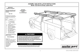
All Purpose Rack - Models 205 • 215 • 216 • 2055 • 2056
Rev. 6/05 Part No. 24-0224
TOOLS REQUIRED
• 7/16" Open or Box End Wrench
• 9/16" Open or Box End Wrench
NOTE: We have found varying
tolerances between the top of
the doors and the rain gutters
on the 1992 to present full-size
vans. Before placing van rack on
vehicle, check the door clear-
ance with the bottom clamp, by
holding it to the underside of the
rain gutter and slowly opening
the door. If the door hits, you
will have to move the clamp to
where more clearance is avail-
able. Some cases may require
moving the clamps rearward of
the driver and passenger side
doors.
Figure 1. Model 205 All Purpose Rack shown installed
WARNING
This product is only intended for, and only safe for, transporting
ladders, lumber, pipe and other similar materials. It is the respon-
sibility of the user to secure these materials to the rack before
transporting. Any modifications made to this product, or use of
this product for any other purpose than its intended use, could
create a hazardous condition that can cause serious personal
injury or property damage.
IMPORTANT
BEFORE YOU BEGIN
Read these instructions and
warnings completely before
installation.
Model 205 215 2055
216 2056 Description
Bolt Kit 32-0146 32-0147 32-0148
Quan. 8 12 4 1/4-20 x 1-1/2" Carriage Bolt
8 12 4 1/4-20 Nylon Lock Nut
8 12 4 1/4" Flat Washer
7 10 3 3/8-16 x 3/4" Thread Cutting Bolt
BOLT KITS
The following bolt kits are provided with each model. Check
the bolt kit to be sure the following parts are included:
The distinctive, trademarked RED TIPS
are your assurance of WEATHER
GUARD® Equipment quality.
CAUTION
Load should be approximately centered
front to rear on all vehicles. Failure to do
this will cause damage to the vehicle roof.
Approximate Assembly and Installation time:
205: 36 min. per unit (.6 hrs.)
215 & 216: 48 min. per unit (.8 hrs.)
2055 & 2056: 18 min. per unit (.3 hrs.)
Depending on van equipment installation experience
8 12 4 1/4-20 x 1" Carriage Bolt

205 215 216* 2055 2056* Description
4 6 4 2 0 Stand (p/n 23-0198)
0 0 2 0 2 Center Stand (Ford) (p/n 23-0199)
1 2 2 1 1 Crossmember (p/n 20-0188)
4 6 6 2 2 Universal Clamp (p/n 21-0826)
2 3 3 1 1 Tie Down Loops (p/n 23-0109)
4 6 6 2 2 Mounting Cushion (p/n 21-0629)
1 1 1 1 1 Sealant (p/n 21-9121)
4 6 6 2 2 Spacer, Clamp (p/n 21-0827)
1 1 1 0 0 Ladder Stop Assembly
2 2 2 0 0 Ladder Straps
1 1 1 0 0 Front Crossmember (p/n 23-0394)
2
PARTS LIST
Figure 3. Center Stand Identification
*NOTE: Models 216 and 2056 are
used exclusively on Ford and Chevy
GMT600/GMC Savana vans due to
the upward bow in the center of the
gutter. The front and rear Stands have
7" long sockets. The third (center)
Stand can be identified by the 5"
socket that is 5/8" lower (
Stand B as
shown in Figure 3.
) for the Ford and
GM.
Crossmember
Front Crossmember
(strap loop this end)
Mounting
Cushion
Ladder Stop
Assembly
(fasten loosely)
Figure 4. Rack Assembly
(tighten all fasteners after assembly)
3/8-16 x 3/4" Thread
Cutting Screw
Socket
Ladder Strap
Step 1. Rack Assembly
The Ladder Stop Assembly will face
rearward on the rear Crossmember/
Stand Assembly. If desired, it may be
assembled on the driver side. Fasten
the Crossmembers in the Stands.
Tie Down Loop
(fasten loosely)

Step 3. Fasten Clamps.
Fasten the clamps to the Stands ac-
cording to your application. See below
for GM application and Page 4 for all
other applications
3
Figure 7. Clamping to a GM van
Step 2. Rack placement.
The preferred rack placement will lo-
cate the rear of the front stands even
with the rear edge of the front doors.
When installing a three crossmember
van rack, use the dimensions shown in
Figure 5
.. All measurements are from
center to center of the stands. The van
rack placement on the roof can vary
somewhat, and the dimensions
(
shown in Figure 5.
) may vary due to
variations in the gutter bow.
NOTE: Gutter widths vary, some vans
will require the Crossmember to be
cut. All Crossmembers for Chevy GMT
600/GMC Savana vans will have to be
cut to length, as well as the rear
Crossmember on a Ford van. Insert
each crossmember end into a Stand.
Carefully place each Crossmember/
Stand in position (
see Figure 5.
), laying
the Crossmember on/across the roof.
On the opposite side of the van from
the Stands, place a Stand in the gutter
so the Stand socket is alongside the
Crossmember. Raise the Crossmem-
ber end off the roof so that it and the
Stand socket are horizontal. Mark the
Crossmember 1" short of the Stand
upright tube. Remove the Stand and
Stand Crossmember from the van. Cut
the Crossmember end off at the mark.
Figure 5. Stand
Placement Dimensions
Figure 6. Breaking Weld
NOTE: Some vans have a guard over the
sliding door track, spot welded in place. If
the Clamp will not fit between the
spotwelds, see
Figure 6
. If the Clamp will
not fit between the spot welds, place a flat
screwdriver at the restricting weld and
strike it with a hammer to break the weld.
This will give the guard flexibility to insert
the clamp under the rain gutter.
1/4-20 Nylon
Lock Nut
1/4" Flat
Washer
Clamp,
Universal
1/4-20 x 1"
Carriage Bolt
Caulk
GM application: The Stand must con-
tact the roof gutter,the Clamp must en-
gage under the gutter, and the bolt
holes must align as shown in
Figure 7
.
DO NOT install as shown in
Figure 8
.
Due to excess body caulk in some gut-
ters on GM vans, the Carriage Bolts
will be unable to align to the holes in
the Stands. In those cases, a portion
of the caulk might have to be cut out of
the gutter and then re-caulked after
the rack is installed.
Figure 8. Example of unacceptable
mounting. Not enough engagement of
clamp and Stand does not contact bot-
tom of gutter.

If you have any questions, please give us a call. Call Toll Free 1-800-456-7865
WEATHER GUARD® products are protected by one or more of the following trademarks:
U.S. - 842268, 1661625, 1663369, 1750034, 2228051, 1643535; Canada - 282725; U.K. - 1400720;
N.Z. - 296049; Aus. - 761964 other trademarks pending.
KNAACK MANUFACTURING COMPANY
420 E. TERRA COTTA AVENUE - CRYSTAL LAKE, ILLINOIS, USA 60014
©2005 Knaack Manufacturing Company
-NOTICE-
Any modification or unintended use of this product shall immediately void all manufacturers warranties.
Manufacturer disclaims all liability for injuries to persons or property resulting from any modification to, or
unintended use of this product.
WARRANTY WILL BE
VOID IF SEALANT IS
NOT APPLIED TO ALL
SEAMS AND CREVICES
WARNING
Ladders must be secured per
ANSI standard A142.2-1990
paragraph 8.4.4. Ladder dam-
age will occur from road shock
and vehicle vibration if the lad-
der is not properly secured to
the ladder rack. Bouncing and
side to side motion of a im-
properly secured ladder will
cause wear and weaken the
ladder. Using a damaged ladder
could lead to a structural col-
lapse and could result in a seri-
ous injury or death.
Step 4. Sealant
Seal all seams and crevices, such as
socket tube ends.
Step 5. Tie Down Loop and
Ladder Stop.
Secure the Tie Down Loop to the
Crossmember after determining where
you want it to hold your ladder. With a
Ladder on the rack, locate the Ladder
Stop inside of the ladder and then se-
cure. Insert a strap through the loop on
the Ladder Stop and on the front
Crossmember. Refer to the warning
decal on the Ladder Stop.
Clamp,
Universal
Figure 9. Clamping to a Ford or Dodge
1/4-20 Nylon
Lock Nut
1/4-20 x 1-1/2"
Carriage Bolt
1/4" Flat
Washer
Spacer,
Clamp
All other applications: The Stand
must contact the vans gutter and in-
stalled as shown in
Figure 9
. A Spacer
will need to be installed between the
Clamp and the Stand.
At the end of the first week of use,
check all of the fasteners for proper
tightness and then check every three
months thereafter.
/