Page is loading ...

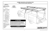
ASSEMBLY AND INSTALLATION INSTRUCTIONS
Model 1425 Aluminum Swivel Rack
IMPORTANT
BEFORE YOU BEGIN
Read these instructions and
warnings completely before
installation.
Part No. 24-0145 REV. B ECN 5315 05/13
BOLT KIT
Bolt kit #32-0021 is provided with
your rack. Check this bolt kit to be
sure the following parts are in-
cluded:
Qty. Description
4 5/16-18 x 1-1/4" Hex Hd Bolt
20 5/16" Flat Washer
2 5/16-18 x 3" Hex Hd. Bolt
14 5/16-18 Nylon Lock Nut
8 5/16-18 x 1-1/4" Carriage Bolt
1 Tube, Sealant - Clear
* See back page for Bolt Chart
TOOLS REQUIRED
• Electric drill
• 3/8" Drill Bit
• 1/2" Open or Box End Wrench
• 3/8" Drive Ratchet
• 1/2" Socket
• Hammer
• Center Punch
• Hacksaw
• Ruler
• Pencil
• Straight Edge - 2' long
CAPACITY
200 lbs.
MAXIMUM
NOTE: This product is to be
installed only on all-steel
service bodies
WARNING
This product is only intended for, and only safe for, transporting
ladders. It is the responsibility of the user to secure the ladder to
the rack before transporting. Any modifications made to this
product, or use of this product for any other purpose than its in-
tended use, will create a hazardous condition that will cause
serious personal injury or property damage.
3

2
Top Front Stand (1)
Lower Front Stand (1)
Collar (1)
Support Angle (2)
Rear Stand (1)
Figure 1. Parts Identification
Refer to this illustration
for part identification
Strap, 1450 (2)

3
CAUTION
To keep debris out of your
eyes when drilling, always
wear protective eyewear.
NOTE: To prevent rust from occur-
ring, touch-up any drilled holes.
1. Front Stand Height - The
Front Stand is pre-drilled for 16" and
30" heights (
See Figure 2.
), and for
mounting on driver or passenger sides
of a vehicle. The height of the Stand is
pre-drilled for heights of 16" & 30", but
can be adjusted anywhere in-between
by drilling additional holes.
NOTE: 30" is the maximum height.
Do not drill any holes below the
bottom hole in the Upper Stand. For
Stand heights of 16" to 20" it will be
necessary to cut 4" off the bottom
of the Upper Front Stand tube. For
heights of 20" to 30", no cutting is
necessary.
For Stand heights between 16" & 30",
using the straight edge, draw a pencil
line on the Upper Front Stand tube
from the center of the upper holes to
the center of the lower holes (
See
Figure 3.
). Insert the Upper Front
Stand tube into the Lower Front Stand
tube, then place the Stand in position
on the service body. Hold the Upper
Front Stand at the desired height in
the Lower Front Stand, allowing for
approximately 2" of clearance between
the roof and the front crossmember
side stops (
See Figure 4.
). Mark the
Upper Front Stand through the Lower
Front Stand slotted hole. Remove the
Upper Front Stand. The mark must be
in-line with the pre-drilled holes, if it is
not, extend the mark so that it crosses
the pencil line. Mark the tube for
another hole, 1-1/2" above the marked
hole for the Collar mounting hole. Drill
these marks with a 3/8" drill bit,
completely through the tube.
ASSEMBLY AND
INSTALLATION
INSTRUCTIONS
Pre-drilled holes
for 16" height
Pre-drilled holes
for 30" height
Figure 2. 16" & 30" height pre-drilled holes
4"
Cut here for Stand
heights of 16" to 20"
Figure 3. Hole alignment
Any holes drilled
in the Upper Front
Stand tube must
be in-line with the
pre-drilled holes

4
Lower Front Stand
5/16-18 x 3"
Hex Head Bolt
(2 places)
5/16" Flat
Washer
(4 places)
Collar
5/16-18 Nylon
Lock Nut
(2 places)
Figure 5. Front Stand Assembly
Upper Front Stand
2. Front Stand Assembly -
Fasten the Upper Front Stand to the
Lower Front Stand through either the
top or bottom set of holes, or the holes
you drilled (
See Figure 5.
). Do not
tighten the bolt for the slot completely,
it must be loose enough so the Stand
will swivel.
Approximately 2"
Figure 4. Roof clearance

5
3. Support Angle Marking -
The Front Stand will be located as
shown in Figure 6. when installed.
From the inside of the service body
"side box", position a Support Angle in
the front upper corner, against the top
and end panel of the box (
See Figure
7.
). Some boxes will require mounting
through the top and back (See Figure
8.), and it may be necessary due to
the construction of the box, to move
the Support Angle away from the
corner. Mark through all six of the
Support Angle holes (
See Figure 7.
and 8.
). Repeat this in the inside back
of the service body with the other
Support Angle at the other end of the
box.
Figure 8. Support Angle Placement
(top & back panel)
Figure 7. Support Angle Placement
(top & end panel)
Figure 6. Stand Placement
End of
Box
Back of
Box
End of
Box
Back of
Box
Placement may vary
due to the construction
of the box

4. Drilling - Drill the marks with a
3/8" drill bit.
NOTE: When installing the Front
and Rear Stands, be sure to use the
sealant provided under all external
fasteners, as well as the mounting
bases of the Stands.
NOTE: When installing the Front
Stand on the driver side, position
the Stand so that it will swivel from
facing the rear of the truck to facing
the side, in a clockwise direction
(
See Figure 9.
). When installing the
Front Stand on the passenger side,
position the Stand so that it will
swivel from facing the rear of the
truck to facing the side, in a counter
clockwise direction (
See Figure
10.
).
5. Front Stand Mounting -
Fasten the Front Stand to the service
body (
See Figure 9.
), again making
sure to use sealant.
5/16-18 x 1-1/4"
Hex Head Bolt
(2 places)
5/16-18 Nylon
Lock Nut
(6 places)
5/16" Flat
Washer
(8 places)
Support
Angle
3/8" Hole
(6 places)
Figure 9. Front Stand Installation (shown on driver side)
Front
of service
body
Direction
of swivel
for Driver
Side
Outside of
service body
5/16-18 x 1-1/4"
Carriage Bolt
(4 places)
CAUTION
Prior to drilling, so as not to
cut electric wires, etc., check
the vehicle for locations.
6

Outside of
service body
Figure 10. Front Stand Installed (shown on passenger side)
Direction
of swivel
for
Passenger
Side
Front of
service body
6. Rear Stand Mounting -
Fasten the Rear Stand to the service
body with the upright tube drain hole
towards the rear of the vehicle (
See
Figure 11.
). The Rear Stand will fasten
to the service body using the same
fasteners shown in
Figure 9.
.
Drain
hole
Rear
of service
body
Figure 11. Rear Stand - mounted
7

If you have any questions, please give us a call. Call Toll Free 1-800-456-7865
Weather Guard® products are protected by one or more of the following patents or trademarks:
U.S. - 842268, 1661625, 1663369, 1750034, 2362167; Canada - 282725; U.K. - 1400720;
N.Z. - 296049; AUS. - 761964; other patents pending.
KNAACK LLC
420 E. TERRA COTTA AVENUE -
CRYSTAL LAKE, ILLINOIS, 60014 - 815-459-6020
©2004 Knaack LLC
- NOTICE -
Any modification or unintended use of this product shall immediately void all manufacturers warranties.
Manufacturer disclaims all liability for injuries to persons or property resulting from any modification to, or
unintended use of this product.
WEATHER GUARD®
REFINISHING PROCEDURES
All Weather Guard® products are
finished with a polyester powder
coating, and it is important to follow
these procedures to get proper
adhesion. As Weather Guard® cannot
control the finishing of the products,
Weather Guard®’s warranty on paint
is not applicable on refinished prod-
ucts.
1. Sand the surface to be painted with
180-200 grit sand paper to rough up
the surface. This should be followed
by wet sanding with a 400 grit wet or
dry paper.
2. Wipe down the sanded surface with
ketone based thinner. This removes
the dust and softens the powder
coating for better paint adhesion.
3. Wipe sanded area with a tack rag to
remove loose dust and particles before
painting.
NOTE: Do not use a lacquer over
the powdered coating.
Bolt Chart
5/16-18
Nylon
Lock Nut
5/16 Flat
Washer
5/16-18 x 1-1/4"
Carriage Bolt
5/16-18 x 1-1/4"
Hex Hd. Bolt
5/16-18 x 3"
Hex Hd. Bolt
WARNING
Ladders must be secured per ANSI
standard A142.2-1990 paragraph 8.4.4.
Ladder damage will occur from road
shock and vehicle vibration if the ladder is
not properly secured to the ladder rack.
Bouncing and side to side motion of a
improperly secured ladder will cause
wear and weaken the ladder. Using a
damaged ladder could lead to a structural
collapse and could result in a serious
injury or death.
Part No. 24-0145 REV. B ECN 5315 05/13
8
/