Page is loading ...

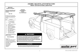
ASSEMBLY AND INSTALLATION INSTRUCTIONS
Aluminum Conduit Carrier - Model 237
Part No. 24-2370 REV. G ECN 5315 05/13
PARTS LIST
• 1- Front Body
• 1- Rear Body Assembly
• 1- Door Assembly
• 1- Door Stop
• Weatherstripping (bulk)
• 2- "U" Clamps
• 4- Clamp Brackets
TOOLS REQUIRED
· 7/16" Open or Box End Wrench (2)
· 3/8" Open or Box End Wrench
· Razor knife or scissors
WARNING
This product is only intended for, and only safe for, storing and
transporting tubing, pipe and conduit. Any modifications made
to this product, or use of this product for any other purpose than
its intended use, could create a hazardous condition that can
cause serious personal injury or property damage.
IMPORTANT
BEFORE YOU BEGIN
Read these instructions and
warnings completely before
installation.
BOLT KIT
Bolt Kit #32-0237 is provided with
your Conduit Carrier. Check this
bolt kit to be sure the following
parts are included:
Quan. Description
4 #12-24 Nylon Lock Nuts
(black dichromate)
10 1/4-20 x 3/4" Hex Hd. Bolt
3 1/4-20 x 5/8" Hex Hd. Bolt
13 1/4-20 Nylon Lock Nuts
20 1/4" Flat Washers
1

1/4-20 x 3/4"
Hex Hd. Bolt
Weatherstrip
Door Assembly
p/n 25-0037C
Clamp Bracket
p/n 20-2390
Weatherstrip
Door Stop
p/n 20-2376C
1/4-20 Nylon
Lock Nut
1/4" Flat Washer
1/4-20 x 5/8"
Hex Hd. Bolt
"U" Clamp
p/n 21-0085
Rear Body Assembly
p/n 25-0035C
Weatherstrip
Front Body
p/n 23-0241C
1/4-20 Nylon
Lock Nut
Weatherstrip
#12-24 Nylon Lock Nut
(black dichromate)
ASSEMBLY INSTRUCTIONS
1. Cut and adhere Weatherstripping
over the Door Stop mounting holes on
the Rear Body Assembly (
see Figure
2.
).
Figure 1. Assembly - Exploded view
2. Place the Door Stop on top of the Rear Body Assembly and
the Door inside. Poke the fasteners through the Weatherstrip,
and loosely fasten the Door Stop and Door. Center the Door
on the Rear Body Assembly, then tighten the bolts (
see
Figure 3.
).
Figure 2. Weatherstripping Rear Body Assembly Figure 3. Door Stop and Door to Body Assembly
Weatherstrip
(cut from bulk)
Rear Body
Assembly
Door Stop
Door
Assembly
1/4-20 x 5/8"
Hex Head Bolt
(3 places)
1/4-20 Nylon
Lock Nut
(3 places)
Rear Body
Assembly
2

3. Open the Door, cut and adhere
Weatherstripping to fit inside the Door
where it touches the Rear Body Assem-
bly (
see Figure 4.
). Be sure you don’t
cover the latch hole.
6. Place the assembled unit on the ve-
hicle roof rack, positioning as shown in
Figure 7.
, and allowing for rear door
swing-up when installed on some mini
vans.
4. Cut and adhere Weatherstripping to
fit the attaching flanges on the Front
Body (
see Figure 5.
).
5. Fasten the Front Body to the Rear
Body Assembly (
see Figure 6.
). It will be
necessary to poke the bolts through the
adhered Weatherstripping.
Figure 4. Door Assembly Weatherstripping Figure 5. Front Body Weatherstripping
Figure 6. Rear Body Assembly to Front Body fastening
1/4-20 Nylon
Lock Nut
(10 places)
Rear Body
Assembly
1/4" Flat
Washer
(20 places)
Front
Body
1/4-20 x 3/4"
Hex Head Bolt
(10 places)
Weatherstrip
(cut from bulk)
Weatherstrip
(cut from bulk)
Attaching
Flanges
Front
Body
Figure 7. Mini Van Door Clearance
3

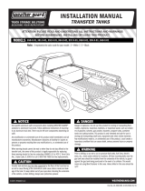
If you have any questions, please give us a call. Call Toll Free 1-800-456-7865
Weather Guard® products are protected by one or more of the following patents or trademarks:
U.S. - 842268, 1661625, 1663369; Canada - 282725; U.K. - 1400720; other patents pending.
KNAACK LLC
420 E. TERRA COTTA AVENUE - CRYSTAL LAKE, ILLINOIS, 60014 - 815-459-6020
- NOTICE -
Any modification or unintended use of this product shall immediately void all manufacturers warranties.
Manufacturer disclaims all liability for injuries to persons or property resulting from any modification to, or
unintended use of this product.
Figure 9. Body to Crossmember Fastening
Figure 10b. Installation on a channel
shaped crossmember
8. Place the Conduit Carrier in position
on the van rack. Install the "U" Clamps
and Clamp Brackets (
see Figure 9.
).
(
See Figures 10a, 10b or 10c for instal-
lation of "U" Clamps and Clamp Brack-
ets for your crossmember
).
7. Mark the Conduit Carrier where it lays
on the van rack crossmembers. Remove
the Conduit Carrier from the van rack.
Adhere Weatherstripping to the under-
side of the unit where it laid on the
crossmembers (
see Figure 8.
).
Weatherstrip
(cut from bulk)
Figure 8. Assembly Weatherstripped for Crossmember
"U" Clamp
(2 places)
#12-24 Nylon
Lock Nut
(4 places)
Clamp Bracket
(4 places)
Figure 10a. Installation on a 211
aluminum crossmember
Figure 10c. Installation on a square
shaped crossmember
Part No. 24-2370 REV. G ECN 5315 05/13
4
©2000 Knaack LLC
/