PEAK PCAN-PC/104-Plus User manual

Type
User manual

This manual is also suitable for

PCAN-PC/104-Plus
CAN Interface for PC/104-Plus
User Manual
Document version 2.5.0 (2019-03-06)
PCAN-PC/104-Plus – User Manual
2
Relevant products
Product name Model Part number
PCAN-PC/104-Plus Single
Channel
One CAN channel IPEH-002094
PCAN-PC/104-Plus Dual
Channel
Two CAN channels IPEH-002095
PCAN-PC/104-Plus Single
Channel opto-decoupled
One CAN channel, galvanic
isolation for CAN connection
IPEH-002096
PCAN-PC/104-Plus Dual
Channel opto-decoupled
Two CAN channels, galvanic
isolation for CAN connections
IPEH-002097
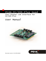
The cover picture shows the product PCAN-PC/104-Plus Dual Channel opto-
decoupled. Other product versions have an identical form factor but vary in
equipment.
On request you can get the product versions with stack-through connectors for the
ISA bus.
PCAN® is a registered trademark of PEAK-System Technik GmbH. CANopen® and
C
iA® are registered community trade marks of CAN in Automation e.v.
All other product names mentioned in this manual may be the trademarks or
registered trademarks of their respective companies. They are not explicitly marked
by “™” and “®”.
Copyright © 2019 PEAK-System Technik GmbH
Duplication (copying, printing, or other forms) and the electronic distribution of this
document is only allowed with explicit permission of PEAK-System Technik GmbH.
PEAK-System Technik GmbH reserves the right to change technical data without
prior announcement. The general business conditions and the regulations of the
license agreement apply. All rights are reserved.
PEAK-System Technik GmbH
Otto-Roehm-Strasse 69
64293 Darmstadt
Germany
Phone: +49 (0)6151 8173-20
Fax: +49 (0)6151 8173-29
www.peak-system.com
info@peak-system.com
Doc
ument version 2.5.0 (2019-03-06)
PCAN-PC/104-Plus – User Manual
3
Contents
1 Introduction 5
1.1 Properties at a Glance 5
1.2 System Requirements 6
1.3 Scope of Supply 7
2 Configuring and Installing the Card and the
Software 8
2.1 Configuring the Card 8
2.1.1 Setting the Position in the PC/104
Stack 8
2.2 Installing the Software and the Card 10
2.3 Notes for the ISA Bus Stack-through
Connection 12
3 Connecting the CAN Bus 13
3.1 Connection over D-Sub connector 13
3.1.1 Slot Bracket with D-Sub Connectors 15
3.2 Voltage Supply of External Devices 16
3.3 Cabling 18
3.3.1 Termination 18
3.3.2 Example of a Connection 18
3.3.3 Maximum Bus Length 19
4 Software and API 20
4.1 Monitor Software PCAN-View 20
4.1.1 Receive/Transmit Tab 22
4.1.2 Trace Tab 24
4.1.3 PCAN-PC/104-Plus Tab 25
4.1.4 Status Bar 25
4.2 Linking Own Programs with PCAN-Basic 26
4.2.1 Features of PCAN-Basic 27
4.2.2 Principle Description of the API 28
4.2.3 Notes about the License 29
PCAN-PC/104-Plus – User Manual
4
5 Technical Specifications 30
Appendix A CE Certificate 32
Appendix B Dimension Drawing 33
Appendix C Quick Reference 34
PCAN-PC/104-Plus – User Manual
5
1 Introduction
The PCAN-PC/104-Plus card enables the connection of one or two
CAN networks to a PC/104-Plus system. Up to four cards can be
operated, with each piggy-backing off the next. The CAN bus is
connected using a 9-pin D-Sub plug on the slot bracket supplied.
The card is available as a single or dual-channel version. The opto-
decoupled versions also guarantee galvanic isolation of up to 500
Volts between the PC and the CAN sides.
The monitor software PCAN-View and the programming interface
PCAN-Basic for the development of applications with CAN
connection are included in the scope of supply.
Device drivers exist for different operating systems, so programs
can easily access a connected CAN bus.
Tip: At the end of this manual (Appendix C) you can find a
Quick Reference with brief information about the installation
and operation of the PCAN-PC/104-Plus card.
1.1 Properties at a Glance
Form factor PC/104
Use of the 120-pin connection for the PCI bus
Up to four cards can be used in one system
1 or 2 High-speed CAN channels (ISO 11898-2)
Bit rates from 5 kbit/s up to 1 Mbit/s
Compliant with CAN specifications 2.0A (11-bit ID)
and 2.0B (29-bit ID)
PCAN-PC/104-Plus – User Manual
6
Connection to CAN bus through D-Sub slot bracket,
9-pin (in accordance with CiA® 303-1)
NXP SJA1000 CAN controller, 16 MHz clock frequency
NXP PCA82C251 CAN transceiver
5-Volt supply to the CAN connection can be connected through a
solder jumper, e.g. for external bus converters
Galvanic isolation on the CAN connection up to 500 V (only
opto-decoupled versions), separate for each CAN channel
Extended operating temperature range from -40 to 85 °C
(-40 to 185 °F)
Optionally available: PCI/104-ISA stack-through connector
Note: This manual describes the use of the PCAN-PC/104-Plus
card with Windows. You can find device drivers for Linux and
the corresponding application information on the provided DVD
in the directory branch Develop and on our website under
www.peak-system.com/linux.
1.2 System Requirements
PC/104 stack with PCI-Bus (according to the specification PC/104-
Plus)
Operating system Windows 10, 8.1, 7 (32/64-bit)
or Windows CE 6.x (x86 and ARMv4 processor support)
or Linux (32/64-bit)
PCAN-PC/104-Plus – User Manual
7
1.3 Scope of Supply
PCAN-PC/104-Plus card
Slot bracket with D-Sub connectors for the CAN bus
Device drivers for Windows 10, 8.1, 7, and Linux (32/64-bit)
Device driver for Windows CE 6.x
(x86 and ARMv4 processor support)
CAN monitor PCAN-View for Windows
Programming interface PCAN-Basic for developing applications
with CAN connection
Programming interfaces for standardized protocols from the
automotive sector
Manual in PDF format
PCAN-PC/104-Plus – User Manual
8
2 Configuring and Installing
the Card and the Software
This chapter covers the configuration and the software setup for the
PCAN-PC/104-Plus card under Windows and the installation of the
card in the PC/104 stack.
Note: Under Windows the PCAN-PC/104-Plus card is run as a
PCI card.
2.1 Configuring the Card
Before installing the PCAN-PC/104-Plus card into a PC/104 stack, you
may have to configure it using jumpers on the PCB.
Attention! Electrostatic discharge (ESD) can damage or destroy
components on the card. Take precautions to avoid ESD.
2.1.1 Setting the Position in the PC/104 Stack
F
or communication with the host the PCAN-PC/104-Plus card uses
the PCI interface where specific relations between the lengths of the
signal lines must be met. Different line lengths result from different
positions of a PC/104-Plus card in a PC/104 stack.
Therefore, the PCAN-PC/104-Plus card must be adjusted to a specific
position in the stack by setting the appropriate jumpers. The spatial
distance to the host results in the index for the assignment of the
jumpers.
PCAN-PC/104-Plus – User Manual
9
Figure 1: Position of the jumpers J7, J8, J9
on the PCAN-PC/104-Plus card
Position in the PC/104 stack
Jumper Signal
1 2 3 4
J7 ID Select 0 1 2 3
J8 Clock Select 0 1 2 3
J9 Interrupt Select A B C D
PCAN-PC/104-Plus – User Manual
10
2.2 Installing the Software and the Card
This chapter covers the software setup for the PCAN-PC/104-Plus
and the installation of the card in the PC/104 stack.
Install the driver before
you install the card.
Do the following to install the driver:
1. Start Intro.exe from the supplied DVD.
The navigation program starts.
2. Select in the main menu Drivers and click on Install now.
3. Confirm the message of the User Account Control related to
"Installer database of PEAK Drivers".
The driver setup starts.
4. Follow the program instructions.
PCAN-PC/104-Plus – User Manual
11
Do the following to install card into the PC/104 stack:
Attention! Electrostatic discharge (ESD) can damage or destroy
components on the card. Take precautions to avoid ESD.
1. Plug a cable from the slot bracket to a 10-pin socket for each
CAN connection.
Figure 2: Position of the sockets for the CAN connection,
J4 for CAN channel 1 (upper position),
J5 for CAN channel 2 (lower position, Dual Channel versions only)
2. Shut down the computer.
3. Disconnect the computer’s power supply.
PCAN-PC/104-Plus – User Manual
12
4. Insert the card into the PC/104 stack at the position
configured before (1 to 4).
5. Reconnect the power supply of the computer.
6. Turn on the computer and start Windows.
Windows detects the new hardware and completes the driver
installation.
Do the following to check the operational readiness:
1. Open the Windows Start menu.
2. Type peakcpl and press Enter .
The information window for PEAK hardware appears. The plug-in
card must be displayed in the table on the CAN Hardware tab.
2.3 Notes for the ISA Bus Stack-through
Connection
If you want to use additional modules in the PC/104 stack being
connected via the ISA bus, the connections J1 and J2 must be
equipped with stack-through connectors. On request you get a
respective version of the PCAN-PC/104-Plus card.
Taking the host as point of view, PC/104 modules with ISA bus must
be plugged onto the stack behind any module with PCI bus. The
signals of the ISA bus are connected through and not used by the
PCAN-PC/104-Plus card.
PCAN-PC/104-Plus – User Manual
13
3 Connecting the CAN Bus
3.1 Connection over D-Sub connector
A High-speed CAN bus (ISO 11898-2) is connected to the 9-pin
D-Sub connector. The pin assignment for CAN corresponds to the
specification CiA® 303-1.
Figure 3: Pin assignment High-speed CAN bus
(view onto a D-Sub connector of the slot bracket)
Low power devices (e.g. bus converters) can be supplied directly
with 5 volts over pin 1 and/or pin 9 of the CAN connector. Pin 1
and/or pin 9 are not in use at the delivery state. For more
information see the next section 3.2 on page 16.
PCAN-PC/104-Plus – User Manual
14
The pin assignment between a 10-pin socket on the PCAN-PC/104-
Plus card and a D-Sub male connector is as follows:
Figure 4: Numbering at the 10-pin socket
Pin Assignment Assignment
D-Sub
1 +5 V (optional) 1
2 GND 6
3 CAN_L 2
4 CAN_H 7
5 GND 3
6 not connected 8
7 not connected 4
8 +5 V (optional) 9
9 not connected 5
10 not connected
Tip: Connect a CAN bus with a different transmission standard
via a bus converter. PEAK-System offers different bus converter
modules (e.g. PCAN-TJA1054 for a Low-speed CAN bus
according to ISO 11898-3).
PCAN-PC/104-Plus – User Manual
15
3.1.1 Slot Bracket with D-Sub Connectors
Figure 5: Single channel slot bracket
Figure 6: Dual channel slot bracket
To connect a CAN bus to the PCAN-PC/104-Plus card, use the
supplied slot brackets. After you have connected the cables from
the slot bracket with the 10-pin sockets, you can connect the CAN
busses with the D-Sub sockets.
PCAN-PC/104-Plus – User Manual
16
3.2 Voltage Supply of External Devices
External devices with low power consumption (e.g. bus converters)
can be directly supplied via the CAN connector (independently for
each connector on the Dual Channel versions). With a solder bridge
per CAN channel on the PCAN-PC/104-Plus board, a 5-Volt supply
can optionally be routed to pin 1 and/or pin 9 of the D-Sub
connector. The current output is limited to 100 mA.
The opto-decoupled versions of the card contain an interconnected
DC/DC converter. Therefore, the current output is limited to 50 mA.
Do the following to activate the voltage supply:
Risk of short circuit! Solder with great care to avoid unwanted
short circuits on the card.
Attention! Electrostatic discharge (ESD) can damage or destroy
components on the card. Take precautions to avoid ESD.
Set the solder bridge(s) on the card according to the desired
settings.
Figure 7 shows the solder field positions on the card. The table
be
low contains the possible settings.
PCAN-PC/104-Plus – User Manual
17
Figure 7: Positions of the solder fields on the PCAN-PC/104-Plus card
for a 5-Volt supply (JP1 upper position, JP2 lower position)
5-Volt supply
D-Sub connector
Solder field
Without
(Standard)
Pin 1 Pin 9 Pin 1 and
pin 9
CAN 1 JP1
CAN 2 JP2
Note: The pin labels for the CAN connector are related to the 9-
pin D-Sub connector being connected via a cable to a socket on
the card.
Risk of short circuit! The 5-Volt supply is not protected
separately. Therefore, turn off the computer before you
connect and disconnect CAN cables or peripheral systems.
PCAN-PC/104-Plus – User Manual
18
3.3 Cabling
3.3.1 Termination
A High-speed CAN bus (ISO 11898-2) must be terminated with 120
ohms at both ends. The termination prevents interfering signal
reflections and ensures the proper operation of the transceivers of
the connected CAN nodes (CAN interfaces, control devices).
The PCAN-PC/104-Plus card does not have an internal termination.
Use the card on a terminated CAN bus.
3.3.2 Example of a Connection
Figure 8: Simple CAN connection
This example shows a connection between the PCAN-PC/104-Plus
card and a control unit. The connection cable is terminated with 120
ohms at both ends.
PCAN-PC/104-Plus – User Manual
19
3.3.3 Maximum Bus Length
High-Speed-CAN networks may have bit rates of up to 1 Mbit/s. The
maximum bus length depends primarily on the bit rate.
The following table shows the maximum possible CAN bus length
at different bit rates:
Bit rate Bus length
1 Mbit/s 40 m
500 kbit/s 110 m
250 kbit/s 240 m
125 kbit/s 500 m
50 kbit/s 1.3 km
20 kbit/s 3.3 km
10 kbit/s 6.6 km
5 kbit/s 13.0 km
The listed values have been calculated on the basis of an idealized
system and can differ from reality.
PCAN-PC/104-Plus – User Manual
20
4 Software and API
This chapter covers the provided software PCAN-View and the
programming interface PCAN-Basic.
4.1 Monitor Software PCAN-View
PCAN-View is simple Windows software for viewing, transmitting,
and logging CAN and CAN FD messages.
Note: This chapter describes the use of PCAN-View with a CAN
adapter.
Figure 9: PCAN-View for Windows
  • Page 1 1
  • Page 2 2
  • Page 3 3
  • Page 4 4
  • Page 5 5
  • Page 6 6
  • Page 7 7
  • Page 8 8
  • Page 9 9
  • Page 10 10
  • Page 11 11
  • Page 12 12
  • Page 13 13
  • Page 14 14
  • Page 15 15
  • Page 16 16
  • Page 17 17
  • Page 18 18
  • Page 19 19
  • Page 20 20
  • Page 21 21
  • Page 22 22
  • Page 23 23
  • Page 24 24
  • Page 25 25
  • Page 26 26
  • Page 27 27
  • Page 28 28
  • Page 29 29
  • Page 30 30
  • Page 31 31
  • Page 32 32
  • Page 33 33
  • Page 34 34

PEAK PCAN-PC/104-Plus User manual

Type
User manual
This manual is also suitable for

Ask a question and I''ll find the answer in the document

Finding information in a document is now easier with AI