Page is loading ...

NC 617
ATTIC LADDER PRE-INSTALLATION GUIDELINES
“FAKRO” and the FAKRO logo are registered trademarks of FAKRO Group.
All specifications are subject to change without prior notice.
©2009 FAKRO GROUP
FAKRO AMERICA, L.L.C.
311 W. Laura Dr
Addison, IL 60101, USA
tel. (630) 543-1010
e-mail: sales@f
akrousa.com
www.fakrousa.com
www.fakro.com
http://shop.fakrousa.com
LWM / LWM-P
OWM / OWM-P
LST / LSF
LWS-M /LWS-P /LWF /OLN /OLN-P
SKYWIN
77 Woodland Ave
Chatham ON N7L 2S5, CANADA
tel. (519) 352-6587
www.fakro.ca
www.atticstairsus.com

9
INSTALLERS, CARPENTERS, CONTRACTORS
- Read all warning notes. Warning notes contain
important safety tips.
- In order to assure safe use of the attic ladder,
proceed according to the installation instruction.
- The attic ladder is not safe to use, unless it is
completely installed according to the following
instructions.
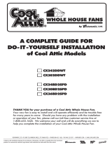
Fig.18. W - Distance between the ceiling joists.
Fig.19.
Installation of stringers
STEP 1
Measure the length of the stringer “W” between the cross-beams
(Figure18). The measurement should be perpendicular to the headers.
STEP 2
Cut the stringer to size. Use timber similar in size to the existing
ceiling joists.
STEP 3
If the joists do not make up the other two sides of the frame, you
need to install one more stringer of the same length as before. On
Figure 18 only one stringer is needed because the ceiling joist
makes up one side of the frame.
STEP 4
Position the stringer (or stringers) along the unframed side if the
ceiling opening (Figure19). The inside dimensions of the frame
should be equal to the ceiling opening (see Table 2 on Page 5).
STEP 5
In order to install stringers to the headers you should use nails long
enough to go through both cross-beams and enter the stringer at least
1”. In most cases it should be 20d nail 4” long. Square the stringer
and drive 3 nails at each end through the double header. Both meas-
ured dimensions should be within 1/8” to consider them equal.

8 1
Table of content
I. Important issues to consider . . . . . . . . . . . . . . . . . . . . . . . . . . . . . . . . . . . . . . . . . . . . . . . . . . . .pages 2
- are you able to install attic ladder? . . . . . . . . . . . . . . . . . . . . . . . . . . . . . . . . . . . . . . . . . . . . .pages 2
- will attic ladder satisfy your expectations? . . . . . . . . . . . . . . . . . . . . . . . . . . . . . . . . . . . . . . . .pages 2
- does the construction of your ceiling enables installation of the attic ladder? . . . . . . . . . . . . .pages 2
II. Your package should contain . . . . . . . . . . . . . . . . . . . . . . . . . . . . . . . . . . . . . . . . . . . . . . . . . . .pages 3
III. Required manpower, tools and materials . . . . . . . . . . . . . . . . . . . . . . . . . . . . . . . . . . . . . . . . . .pages 3
IV. Finding a suitable locations for installation . . . . . . . . . . . . . . . . . . . . . . . . . . . . . . . . . . . . . . . . .pages 4
V. Cutting a hole in the ceiling . . . . . . . . . . . . . . . . . . . . . . . . . . . . . . . . . . . . . . . . . . . . . . . . . . . .pages 5
VI. Cutting the ceiling joists . . . . . . . . . . . . . . . . . . . . . . . . . . . . . . . . . . . . . . . . . . . . . . . . . . . . . . .pages 6
VII. Framing the installation opening . . . . . . . . . . . . . . . . . . . . . . . . . . . . . . . . . . . . . . . . . . . . . . . . .pages 7
- installing the single headers . . . . . . . . . . . . . . . . . . . . . . . . . . . . . . . . . . . . . . . . . . . . . . . . . . .pages 7
- double headers . . . . . . . . . . . . . . . . . . . . . . . . . . . . . . . . . . . . . . . . . . . . . . . . . . . . . . . . . . . .pages 8
- installation of stringers . . . . . . . . . . . . . . . . . . . . . . . . . . . . . . . . . . . . . . . . . . . . . . . . . . . . . . .pages 9
Double headers
STEP 1
Measure the length of the header “P” between uncut joists
(Figure15). The measurement should be done perpendicular to
the joists.
STEP 2
Cut to size 4 headers. For that purpose use timber similar in size
to existing joists.
STEP 3
Position one header at the end of the cut out joist (Figure16). It
must fit tightly between the uncut joists. If needed use a hammer
to set the header in the appropriate place.
STEP 4
Square the header to one joist and drive 3 nails (16d) on both
ends and to the cut joist (Figure 16).
STEP 5
Position the second header in front of the first one and nail it
(Figure 17).
STEP 6
Repeat steps 3-5 in order to install headers at the other side of the
ceiling opening.
STEP 7
In order to install other elements of the frame proceed to section
“installation of stringers”.
Fig.15. P - Distance between the ceiling joists.
nails
Fig.16.
nails
Fig.17.

2 7
Before you start any work read carefully all instructions, in order to
make sure that you have a proper spot for installation and tools.
Are you able to install attic ladder?
In order to install this attic ladder, you need to know how to cut
wood and use framing square. Not being able to do the above,
installation of this product should be done by a professional
installer (refer to yellow pages).
Will attic ladder satisfy your expectations?
The attic ladder has been designed only for home use. Installation
of this product in commercial buildings can be obstructing to exist-
ing building codes. Before installation of this product consult with
Fire Department or your local building inspector.
The attic ladder has been designed to be installed in room where
the ceiling height is in the range described on the packaging. This
product should not be installed if the ceiling height does not fit in
the range described on the product's label. Modifications of the
attic ladder can be dangerous.
Does the construction of your ceiling enables installa-
tion of the attic ladder?
The attic ladder can be installed in buildings with typical wood
framed ceiling (Figure1). You should never cut any of the con-
structing elements of the ceiling without prior consultation with an
architect (refer to yellow pages).
The attic ladder should not be installed in chosen spot if there is
one of the following:
— air ducts
— metal constructions
— cement ceiling
— drop ceiling
If your ceiling has one of the above elements you can not install
the attic ladder. In this case you should seek professional help.
The following instruction describes the installation
method of the attic ladder.
WARNING! DO NOT CUT THIS TYPE OF CONSTRUC-
TION (FIG. 2, 3) WITHOUT PRIOR CONSULTATION
WITH AN ARCHITECT.
Fig.3. Truss roof frame.
Fig.1. Typical roof construction
Fig.2. Typical construction of the roof with braces connected to the ceil-
ing joists.
I. IMPORTANT ISSUES TO CONSIDER
Before you begin:
the distance between the joists should be the same as the width of installation opening. All cut joists must be attached to the joists that have not
been cut.
WARNING!
For your own safety mind all dangerous elements above your head. Do not sit on the ceiling - it is not designed to carry load.
Only joists will withstand load. In order to make a working area place several boards across the ceiling joists.
VII. FRAMING THE INSTALLATION OPENING
If none of the joists were cut proceed to section “single header”.
If one or more joists were cut proceed to section “double headers”
on page 8.
Single header
s
STEP 1
Measure the distance between the ceiling joists. The measurement
should be done perpendicular to the joist (Figure12).
STEP 2
Cut 2 boards for headers to the measured length. Use timber
material similar in size to the joists.
STEP 3
Position the header at one end of the installation opening
(Figure13). The header must tightly fit between the joists. If need-
ed use a hammer to position the header.
Step 4
Align the header at 90
o
angle to the joists and drive 3 nails (16D)
at each end.
STEP 5
Position the second header 31”, 47” or 54” apart from the first
one and repeat step 4 (Figure 14). The distance between the
headers depends on ladder model.
STEP 6
The frame must have four sides w here the headers are two of
them. If the ceiling joists are positioned as the other two sides
check the angles by measuring the diagonals. Both measured
dimensions should be within 1/8” to consider them equal.
If the ceiling joists do not make the other two sides of the frame,
you should install one or two wooden elements in order to make
the frame in the ceiling opening. Proceed to section “installation of
stringers”.
Fig.12. P- Distance between the ceiling joists.
Fig.13. Nail the header at both ends.
Fig.14.
Installing the headers

6 3
— Attic ladder fully assembled and ready for installation. You should not dismantle assembled product for installation
— Control rod
Prior to installation inspect the product for any cracks in the wood. Make sure that the metal elements are not damaged and securely fas-
tened.
III. REQUIRED MANPOWER, TOOLS AND MATERIALS
Manpower
— 2 people (one must be able to lift 90 LB and carry it in to the attic)
Materials
— few pieces of joist-sized lumber
— 2 boards 1x4x36” for temporary support
— few boards for working platform in the attic space
— wood shim stock
— 20d sinker nails
— 4” screws for wood
Stepladder
Stepladder should be long enough to allow you to enter the overhead space. Make sure that the ladder will withstand your weight plus the
weight of whatever you are carrying.
WARNING
You should be extremely causious while climbing the ladder, other person should be holding the ladder preventing it from tipping over.
Tools
— flashlight
— claw hammer
— pencil
— hand saw
— tape measure
— framing square
— power drill
— 1/8” drill bit
— tools to cut opening in the ceiling
Safety equipment
— gloves
— safety goggles
— dust mask
II. YOUR PACKAGE SHOULD CONTAIN:
Before you begin:
you should now have the cut out hole in the appropriate spot.
STEP 1
If the room has a ceiling in which you made the opening proceed
to step 2.
If there is no ceiling in place mark the joists according to instruction
A or B, below.
A - If the chosen location is parallel to the ceiling joists, mark the
length of the opening on the top surface of the joist as shown on
Figure 8. Do not cut the joist as marked.
B - If the chosen location is perpendicular to the ceiling joists, mark
the width of the opening on the top surface of the joist as shown
on Figure 9. Do not cut the joist as marked.
STEP 2.
Cut 2 pieces of board similar to the size of the ceiling joist, long
enough to nail them to the ceiling joists on both ends of the open-
ing (Figure10). These boards will provide support to joists which
will be cut out.
STEP 3
Position these boards approximately 2 ft from the opening edge
(Figure 10).
Note
The 2 ft space is required to nail the frame.
STEP 4
Next decide where you will cut the joist see Figure11. The cutting
line should be away from the actual opening twice the thickness of
the frame (usually 3 inches). This will allow to install double head-
ers at both ends of the joist (Figure 17, Page8).
Note
In older homes the thickness of the joist might be greater than what
is currently sold in lumber yards. In such case the cutting line
should be marked at twice the thicknesses of the material which
you will use to build the frame not the joist.
STEP 5
Cut the joist carefully, watching not to cut the ceiling board and
making sure that the cut out joist is even and vertical (square).
Fig.8. Dotted line indicates your chosen location parallel to the joist.
Fig.9. Dotted line indicates your chosen location perpendicular to the
joist.
Fig.10. Dotted line indicates your chosen location.
Fig.11. Dotted line indicates your chosen location.
VI. CUTTING THE CEILING JOISTS

4 5
Before you begin:
make sure that you have required tools, manpower, and the con-
struction of the ceiling is suitable for installation of the attic ladder.
Look for a space free from obstacles and dangers. Make sure that
the space will allow proper installation and use of the attic ladder.
Make sure that the length of the attic ladder is suitable for your ceil-
ing height (Figure 4, Table 1).
STEP 1
Choose potential installation spot. Check dimension of the
required opening, refer to the table 2 on page 5.
If the attic ladder will be installed in the garage consider the loca-
tion of parked cars.
STEP 2
Check the swing clearance. Figure 4 and Table 1.
STEP 3
Check the landing space, so that both legs rest on the floor. Figure
4 Table 1.
STEP 4
If the attic ladder will fit between the ceiling joists and there is no
need for cutting the joists proceed according to step 7 “Framing the
installation opening” Page 7-9.
If it is necessary to cut the ceiling joist proceed according to step
6 “Cutting the ceiling joists” Page 6.
STEP 5
Go in to the attic space and locate the spot for installation.
You can find this location by listening for tapping from below or
measure the space below and in the attic area.
STEP 6
In the installation spot you should do the following:
a) check if there is enough room to work during the installation
b) make sure there are no obstacles (ie. air ducts, electrical instal-
lations, etc.) in the attic area disabling safe installation and use of
the attic ladder.
Warning
In order to check the attic area for the above mentioned obstacles
and dangers put on a dust mask, safety goggles, gloves and prop-
er clothes to prevent cuts caused by mineral wool. Next, slowly lift
up the layer of insulation, do not inhale dust and other particles
which might be dangerous to your health.
STEP 7
If in the chosen spot you find any obstacles, you should find another
spot for installation or contact professionals to remove the obstacle
(refer to yellow pages).
FC floor ceiling height
LS landing space
SC swing clearance
Fig.4. Characteristics of the attic ladder.
IV. FINDING A SUITABLE LOCATION FOR INSTALLATION
Table 1
WARNING!
For your own safety do not sit on the ceiling nor the insulation -
it was not design to carry load. Only the ceiling joists can with-
stand your weight. Mind sharp nails sticking out of the ceiling's
construction. Do not nail anything in to the ceiling that can con-
duct electricity until you are sure that there are no electric wires.
Contact with electric wires can be deadly.
Before you begin:
find a spot which is:
— free form any obstacles in the attic area
— free from obstacles in the ceiling
— big enough to carry out the installation
— big enough to use a step ladder
STEP 1
Prepare the work area. Remove the furniture and cover the floor
with a drop cloth. Remove children and pets to a safe distant area.
STEP 2
Put on the safety goggles, dust mask and gloves. These will pro-
tect your eyes and lungs.
STEP 3
Using a hammer and a chisel make an initial hole near the center
of your chosen location (Figure 5).
STEP 4
Enlarge the initial hole with a hand saw until you can see the joist
(Figure 6)
STEP 5
Trace the cutting lines on the ceiling for the installation opening.
Make sure that one of the traced lines is parallel to the ceiling joist
(Figure7, table 2).
Note:
Having one edge of the opening parallel to the ceiling joist will
allow to use it as part of the frame which will be needed for instal-
lation.
STEP 6
Cut out and remove remaining part of the ceiling according to
traced lines (rectangle) while observing:
a. not to cut any joists, only the ceiling board
b. remove the ceiling board by small pieces, because the ceiling
materials can be very heavy.
STEP 7
If there are joists in the cut out opening proceed to section 6
“Cutting the ceiling joists”.
If there are no joists along or across the opening go to section 7
“Framing the installation opening” Page 7-9.
V. CUTTING A HOLE IN THE CEILING
WARNING!
Do not cut, file nor nail anything to the ceiling until you are sure that the
chosen space for installation is free from dangers and other obstacles.
Contact with electric wires can be deadly.
Fig.7. Draw a ractangle the size of the ceiling opening.
Fig.5. Make an initial hole.
Fig.6. Enlarge the initial hole so that you can see the joist.
Table 2
LWS-P 22/47 67 ½” 57 ½” 7'2” ÷ 8'10”
LWS-M 27/47 67 ½” 57 ½” 7'2” ÷ 8'10”
LWS-P 25/47 67 ½” 57 ½” 7'2” ÷ 8'10”
LWS-P 22/54 75 ½” 64 ½” 7'2” ÷ 10'
LWS-P 25/54 75 ½” 64 ½” 7'2” ÷ 10'
LWS-P 30/54 75 ½” 64 ½” 7'2” ÷ 10'
LWS-P 22/54 74” 54 ⁄” 10' ÷ 10'8”
LWS-P 25/54 74” 54 ⁄” 10' ÷ 10'8”
LWS-P 30/54 74” 54 ⁄” 10' ÷ 10'8”
OLN/OLN-P 22/47 66 ½” 57 ⁄” 7'2” ÷ 8'10”
OLN/OLN-P 25/47 66 ½” 57 ⁄” 7'2” ÷ 8'10”
OLN/OLN-P 22/54 74” 64” 7'11” ÷ 10'
OLN/OLN-P 25/54 74” 64” 7'11” ÷ 10'
OLN/OLN-P 30/54 74” 64” 7'11” ÷ 10'
LWM/LWM-P 22/47 69 ⁄” 60” 7'2” ÷ 8'10”
LWM/LWM-P 25/47 69 ⁄” 60” 7'2” ÷ 8'10”
LWM/LWM-P 22/54 74 ¾”
74 ¾”
74 ¾”
64 ½” 7'2” ÷ 10'
LWM/LWM-P 25/54 64 ½” 7'2” ÷ 10'
LWM/LWM-P 30/54 64 ½” 7'2” ÷ 10'
OWM/OWM-P 22/47 70 ⁄” 6'2” ÷ 8'10”
OWM/OWM-P 25/47 70 ⁄” 6'2” ÷ 8'10”
OWM/OWM-P 22/54 72 ¾”
72 ¾”
72 ¾”
64”
57 ½”
57 ½”
7'1” ÷ 10'
OWM/OWM-P 25/54 64” 7'1” ÷ 10'
OWM/OWM-P 30/54 64” 7'1” ÷ 10'
LWF 22/47 67 ¾” 57 ½”
67 ¾” 57 ½”
7'2” ÷ 8'10”
LWF 25/47 7'2” ÷ 8'10”
LWF 22/54 75 ¾”
75 ¾”
75 ¾”
64 ½” 7'11” ÷ 10'
LWF 25/54 64 ½” 7'11” ÷ 10'
LWF 30/54 64 ½” 7'11” ÷ 10'
LST 22/47
LST 25/47
LSF 22/47
47 ⁄”
47 ⁄”
72 ¾”
63”
67”
56”
60”
72 ¾”
LSF 25/47
9'2½” ÷ 9'10”
9'2½” ÷ 9'10”
8'6½” ÷ 9'6”
LST 22/31
63” 56”
8'6½” ÷ 9'6”
8'6½” ÷ 9'6”
MODEL
SC
LS FC
LWS-P 22/47
LWS-M 27/47
LWS-P 25/47
LWS-P 22/54
LWS-P 25/54
LWS-P 30/54
OLN/OLN-P 22/47
OLN/OLN-P 25/47
OLN/OLN-P 22/54
OLN/OLN-P 25/54
OLN/OLN-P 30/54
LWM/LWM-P 22/47
LWM/LWM-P 25/47
LWM/LWM-P 22/54
LWM/LWM-P 25/54
LWM/LWM-P 30/54
OWM/OWM-P 22/47
OWM/OWM-P 25/47
OWM/OWM-P 22/54
OWM/OWM-P 25/54
OWM/OWM-P 30/54
LWF 22/47 22½” ÷ 47”
LWF 25/47 25” ÷ 47”
22½” ÷ 54”
25” ÷ 54”
LWF 22/54
LWF 25/54
LWF 30/54 30” ÷ 54”
22½” ÷ 47”
27½” ÷ 47”
25” ÷ 47”
22½” ÷ 54”
25” ÷ 54”
30” ÷ 54”
22½” ÷ 47”
25” ÷ 47”
22½” ÷ 54”
25” ÷ 54”
30” ÷ 54”
22½” ÷ 47”
25” ÷ 47”
22½” ÷ 47”
25” ÷ 47”
22½” ÷ 54”
25” ÷ 54”
30” ÷ 54”
22½” ÷ 47”
25” ÷ 47”
22½” ÷ 54”
25” ÷ 54”
30” ÷ 54”
LST 22/47
22½” ÷ 31”
LST 22/31
LST 25/47
22½” ÷ 47”
25” ÷ 47”
LSF 22/47
LSF 25/47
MODEL
Ceiling
opening size
MODEL
Ceiling
opening size
/