Page is loading ...

Installation Instructions
FAILURE TO COMPLY WITH ALL INSTRUCTIONS MAY RESULT IN SERIOUS INJURY
Instrucciones de instalación
NO CUMPLIR TODAS LAS INSTRUCCIONES PODRÍA RESULTAR
EN LESIONES GRAVES
AA1510 / AA1510CA
Instructions d’installation
LE NON-RESPECT DE CES INSTRUCTIONS PEUT ENTRAÎNER
UNE BLESSURE GRAVE

Table of Contents
Page
Before you begin 2
Important questions 3
Step 1 Assembling the ladder 3
Step 2 Fitting additional top stops 4
Step 3 Fitting bottom stops 5
Step 4 Installing the ladder 5
Step 5 Installing the assist arm 6
Step 6 Handrail assembly 7
Step 7 Finishing opening for door 7
Step 8 Hanging the door 8
Step 9
Locating the hole for the door
latch
8-9
Step 10 Attaching the location bracket 9
Step 11 Operating the ladder 10
Appendix Creating a rough opening 11
Section 1.1 Important questions 11
Section 1.2 Tools and materials needed 12
Section 1.3 Finding a suitable location 13
Section 1.4 Cutting a hole in the ceiling 14-16
Section 1.5 Framing the rough opening 16-19
-
Compact Attic Ladder
ALUMINUM
BUILT FOR SMALL ATTIC OPENINGS
Escalera de Compacta Para Ático
ALUMINIO
CONSTRUIDA PARA ABERTURAS DE ÁTICO PEQUEÑAS
PRÉVUE POUR DES OUVERTURES DE GRENIER ÉTROITES
EN ALUMINIUM
Échelle de Grenier Compacte

DOOR MATERIAL REQUIRED
BE SURE TO USE 3/4" CABINET GRADE PLYWOOD.
1 x 3 SOLID WOOD BOARD REQUIRED FOR DOOR FRAME
1 X 2 SOLID WOOD BOARD REQUIRED FOR DOOR JAM
AT THE BEGINNING OF EACH STEP THROUGHOUT
THIS INSTRUCTION MANUAL, FASTENERS AND
COMPONENTS THAT ARE NEEDED WILL BE LISTED.
IF ANY PARTS ARE MISSING OR BROKEN,
PLEASE CALL CUSTOMER SERVICE AT 1-888-523-3370.
TOOLS REQUIRED
STEPLADDER
AWL
SAW
DRILL PLUS 1/2" & 1/16" BIT
LARGE FLAT SCREWDRIVER
PHILLIPS SCREWDRIVER
(small and medium)
ADJUSTABLE WRENCH/PLIERS
TAPE MEASURE/RULER
HAMMER
PENCIL
Before you begin
Closed Requirements Opened Requirements
*At handrail low position - 28"
At handrail top position - 38"
D*
E**A
B
**At handrail low position - 44"
At handrail top position - 54"
68°- 80°
C
Compact Attic Ladder
A Minimum Finished Opening (Length) 21"
B Minimum Finished Opening (Width) 15"
C
Maximum Height 9' 10"
Minimum Height 7'
D* Minimum Stowing Height Required In Attic 28"
E**
Minimum Length Required
Behind Rough Opening
44"
2

Important Questions
Read instructions completely before beginning. This is necessary to ensure that you have a suitable location for the attic
ladder and the ability to safely and properly install it.
Are you capable of installing this attic ladder?
To install this attic ladder you should have sawing, squaring, and aligning skills similar to those required to install a
window or a door frame. If you do not have these skills you should hire a professional carpenter to install this unit
(see the Yellow Pages under “Building Contractors, Carpenters, Home Builders, Home Improvements, or
Contractors-General”).
Does this attic ladder meet your needs?
This attic ladder is for residential use only. Installing this attic ladder in commercial buildings and apartments may violate
building codes that require re-rated ceilings and prohibit storing materials in the overhead space! Check with your local
re marshal or building department before installing the attic ladder.
The capacity of the attic ladder (person plus materials being carried) is 250 pounds.
This attic ladder is made for the range of ceiling heights shown on the packaging. Do not install the attic ladder
in a ceiling that has a height outside of this range. Altering the attic ladder to accommodate other heights
is unsafe and should never be attempted.
THIS ATTIC LADDER COMES WITH HINGES AND LATCH TO INSTALL A DOOR (NOT
INCLUDED). TO MODIFY OR CREATE A NEW OPENING, PLEASE REFER
TO THE APPENDIX (PAGE 11).
For correct identication, the front section of the ladder can be identied by its rounded feet.
1. Carefully push out the tacks (lightly tap with a hammer if necessary) and remove the plastic end caps from the bottom
of the REAR section of the ladder (See Figure A).
2. Slide the hinge guides (B1 & B2) onto the uppermost frame section. The brackets should be positioned outwards with
the double holed half uppermost (See Figure B).
3. Slide all the way up to the installed permanent top stops at other end of section.
4. Do not replace the plastic end caps (see later at Step 3 - Fitting Bottom Stops).
Assembling the Ladder
Step 1
Rear
Front
B2
B1
Right side
Left side
TOOLS REQUIRED
HAMMER
PARTS REQUIRED
B1. (1) HINGE GUIDE - LEFT
B2. (1) HINGE GUIDE - RIGHT
Figure A Figure B
3

Depending on the oor to oor height (see Opened Requirements
left), you may need to add the additional top stops provided (C2)
(see table below).
1. If required, locate the additional top stops over the holes
approximately 6" below the permanent top stops on the rear
section of the ladder (See Figure C).
2. Ensure the hinge guides (B1 & B2) are already in place and
below the additional top stops when assembled.
3. Fix the additional top stops using two M4 bolts and nuts
supplied (C1 & C3).
Fitting Additional Top Stops
Step 2
TOOLS REQUIRED
ADJUSTABLE WRENCH/PLIERS
PARTS REQUIRED
C1. (2) M4 X 8MM TOP STOP BOLTS
C2. (2) ADDITIONAL TOP STOPS
C3. (2) M4 LOCKING NUTS
C1
C2
C3
Operating Heights
Feet & Inches Top Stops Required
7' 0" to 7' 6" YES
7' 6" to 7' 11" NO
7' 11" to 8' 5" YES
8' 5" to 8' 10-1/2" NO
8' 10-1/2" to 9' 4" YES
9' 4" to 9' 10" NO
Opened Requirements
68°- 80°
Floor to
oor height
C1
B2
B1
C2
C3
Permanent top stop
Figure C
4

Fitting Bottom Stops
Step 3
Installing the Ladder
Step 4
TOOLS REQUIRED
LARGE FLAT SCREWDRIVER
PHILLIPS SCREWDRIVER
(small and medium)
HAMMER
PARTS REQUIRED
PARTS REQUIRED
D1. (2) BOTTOM STOPS
D2. (4) 12MM SCREWS
B1. (1) HINGE GUIDE - LEFT
B2. (1) HINGE GUIDE - RIGHT
B3. (6) 35mm SCREWS
D2
D1
D1
D2
6"
1. Both end caps should now have been removed from the
rear section during previous Step 1. Remove end cap
from the rear section rail (on the same side as it is
intended to t the assist arm).
2. Slide the bottom stops (D1) onto the rear rails.
3. Position the bottom stops 6" from the end of
the rails (See Figure D).
4. Secure with screws (D2).
5. Replace the plastic end caps removed previously and
secure with tacks.
B3
B1
B2
WARNING:
DO NOT stand on the ladder to do this. Either
using a second ladder, or from inside the attic
space, secure the hinges using six 35mm
screws supplied.
Minimum 3/4" ooring required to support Compact Attic Ladder (See
Appendix, Page 19, Figure 18). The ladder should be installed on the
same side of the opening as where the door hinges will be located.
1. With the ladder centered in the opening, locate the hinge guide
bracket arms (B1 & B2) on the top edge of the opening frame
(See Figure E).
2. Mark guide holes with a pencil and then predrill pilot holes
(1/16" diameter) for all screws.
3. Attach using 35mm screws (B3).
The bracket arms with two screw holes should be on top.
If ooring material covers the top edge of the opening be certain that
the ladder is completely stable. If necessary use longer screws to
penetrate the frame itself.
The ladder should now be free to swing from the hinges and slide
freely up and down the guides.
TOOLS REQUIRED
STEPLADDER
DRILL PLUS 1/16" BIT
LARGE FLAT SCREWDRIVER
PHILLIPS SCREWDRIVER (small and medium)
PENCIL
Figure D
Figure E
!
5

Installing the Assist Arm
Step 5
PARTS REQUIRED
F1. (1) POWER PIVOT UNIT
F2. (1) HOUSING COVER
F3. (6) 20mm SCREWS
F4. (1) PIVOT TIP
F5. (1) M6 x 40mm BOLT
TOOLS REQUIRED
AWL
LARGE FLAT SCREWDRIVER
PHILLIPS SCREWDRIVER
(small and medium)
ADJUSTABLE WRENCH/PLIERS
F4
F2
F3
F1
F3
F3
1. Position the template cut (from the back of the packaging
card) against either the left or right hand hinge guide
bracket (depending on which chosen side the power pivot
system is to be installed).
2. Using an awl or pencil mark the 6 applicable holes through
the template on to the attic oor (See Figure F).
3. Place the spring housing (F1) in position over the holes
ensuring the arm points AWAY from the rough opening
(with slot in cover on the left-hand side) (See Figure G).
4. Secure the spring housing to the attic oor with 20mm
screws (F3) through the 4 inner holes (See Figure G).
5. Place the housing cover (F2) over the spring housing and
attach using 20mm screws (F3) through the 2 remaining
outer holes (See Figure G)
6. Position the ladder in its fully stowed (closed) position
carefully in the opening.
7. Remove the tack and plastic top cap from the top of the
required side rail of the rear ladder section and discard
(See Figure H).
8. In their place attach Pivot Tip (F4) (See Figure H).
9. Locate the power arm linkage plates on either side of pivot
tip (F4)/ladder rail and align all holes.
10. Secure the rail to the linkage plates using bolt (F5),
washers (F6), nut and nut cap (F7 & F8) (See Figure I).
Ensure bolt (F5) and nut (F7) are tightened sufficiently to
allow the linkage to freely rotate without any looseness.
DO NOT over-tighten the nut as this will restrict smooth
operation of the ladder system.
For Right
Hand
Installation
For Left Hand
Installation
Figure F
Figure G
Figure H
F5
F8
F7
F6
F4
F6
Figure I
F6. (2) PLASTIC WASHERS
F7. (1) M6 LOCKING NUT
F8. (1) NUT CAP
F9. (1) BASE DRILL HOLE TEMPLATE
[ON BACK OF PACKAGING CARD]
6

Handrail Assembly
Step 6
Finishing Opening for Door
Step 7
PARTS REQUIRED
PARTS REQUIRED
E1. (3) HANDRAIL SPACERS
E2. (3) M5 x 60mm BOLTS
E3. (3) 25mm DIAMETER WASHERS
E4. (3) M5 LOCKING NUT
Standard 1 x 3 solid wood board (Door Frame)
Standard 1 x 2 solid wood board (Door Jam)
Your choice of nishing wood
TOOLS REQUIRED
ADJUSTABLE WRENCH/PLIERS
TOOLS REQUIRED
SAW
SCREWS / NAILS
PHILLIPS SCREWDRIVER (small and medium)
The handrail can be attached to either side of the ladder. It is advisable to attach the handle only after attaching the power
pivot arm.
1. Attach the handrail to your chosen side of the rear frame (See Figure J).
2. Use 3 spacers (E1), 60mm bolts (E2), washers and nuts (E3 & E4) supplied.
3. You have a choice of 2 different handrail heights which will be
dependent on the amount of “in-attic” handrail you require (See
Figure J).
Check that all components of the whole assembly are fully secure.
E2
E1
E2
E1
Handrail
1*
1*
1*
2**
2**
2**
E1
E2
E2
E1
E3
E4
Handrail
*Position 1 attaches handrail
in top position.
**Position 2 attaches handrail
in low position.
Note: Position of the handrail
will affect the amount of space
needed in the attic.
Use a standard 1 x 3 solid wood plank for the door frame and a standard 1 x 2 solid wood board for the door jam.
1. Measure the width of the opening and cut the 1 x 3 wood board. Nail the trimmed 1 x 3 wood board to the header.
The bottom of the wood door frame should be ush with drywall on ceiling. Repeat for length of opening. (Figure K)
2. Measure inside width of frame and cut the 1 x 2 wood board. Nail the trimmed 1 x 2 wood board to the wood door
frame recessed the thickness of the door to create the door jam. Repeat for length of frame. (Figure L)
Figure J
Figure K
Figure L
Jam should be recessed
the thickness of door
7
Caution: Use of
materials greater than the
recommended thickness
may make the opening too
small to be usable.

Locating the Hole for the Door Latch
Step 9
PARTS REQUIRED
A1. (1) LATCH
A2. (1) TRAVEL STOP RING
A3. (1) LATCH LEVER
A4. (1) M12 NUT
A7. (1) 12mm SCREW
1. From inside attic, with door fully closed, mark the edge of the
jam on the door with a pencil. Measure back and transfer line to
opposite side of door.
2. Find the mid-point of the door edge opposite the hinged side.
This will give you your center line (See Figure N). Mark with a
pencil.
3. Measure exactly 1" in from the mark that was transferred, mark
with a pencil.
4. Drill a 1/2" hole in the center and sand off any rough edges.
(STEP 9 CONTINUED ON NEXT PAGE)
Door Center Line
1"
1/2" hole
Drill hole in the center
inside of door frame
TOOLS REQUIRED
STEPLADDER
DRILL
1/2" DRILL BIT
SANDPAPER
LARGE FLAT SCREWDRIVER
PHILLIPS SCREWDRIVER (small and medium)
ADJUSTABLE WRENCH/PLIERS
TAPE MEASURE/RULER
PENCIL
Figure N
Hanging the Door
Step 8
PARTS REQUIRED
G5. (2) DOOR HINGES
(8) 3/4" WOOD SCREWS
TOOLS REQUIRED
LARGE FLAT SCREWDRIVER
PHILLIPS SCREWDRIVER (small and medium)
G5
The door thickness should be 3/4" cabinet grade
plywood cut 1/8" smaller than wood door frame
opening (from Step 7 - Finishing Opening for Door)
1. Screw hinges (G5) to one edge of the door using
3/4" wood screws.
2. Attach the hinges to the face of the frame on the
same end as you installed the ladder using 3/4"
wood screws (See Figure M).
Figure M
8

Attaching the Location Bracket
Step 10
PARTS REQUIRED
A5. (1) LOCATION BRACKET
A6. (2) 3/4" WOOD SCREWS
(1) “WARNING” LABEL P/N103552-01
(1) “HOW TO USE” LABEL P/N103553-01
TOOLS REQUIRED
STEPLADDER
AWL
LARGE FLAT SCREWDRIVER
PHILLIPS SCREWDRIVER (small and medium)
TAPE MEASURE/RULER
PENCIL
When turned to the correct position, the catch lever will
engage in the location bracket to hold the door shut. Attach
as follows:
1. Mark a vertical line on the inside of the door jam
corresponding with the center line of the door catch
(See Figure Q).
2. Position the catch location bracket (A5) along the
bottom edge of the wood door jam (See Figure R).
3. Match up the indent mark on the bracket with the
vertical center line.
4. Make guide holes with the awl and attach using 2 of
the 3/4" wood screws supplied (A6).
5. Apply door labels, P/N103552-01 and P/N103553-01,
to the top side of the door, inside the attic.
Thickness
of Door
Door jam
Door Frame
A6
A5
Figure Q
Figure R
A1
A2
A4
Screw hole
A3
Door
A1
A4
A7
A3
A2
A3
A2
45°
Figure O
Figure P
(STEP 9 CONTINUED FROM PREVIOUS PAGE)
5. Pass the latch (A1) through the door hole from the
underside such that the position pointer points toward
the door edge (See Figure O).
6. Place the travel stop ring (A2) over the latch (A1) such
that the screw hole is at 45 degrees to the door center
line (See Figures O and P).
7. Place the latch catch (A3) over the latch (A1) and locate
into the latch groove such that the latch catch points
toward the door near edge and fully locates within the
travel stop ring (A2) (See Figures O and P).
8. Secure the travel stop ring (A2) using 12mm screw (A7).
9. Secure the catch assembly with M12 nut (A4) ensuring
the nut is tightened sufficiently to allow the catch to
rotate freely without any looseness (See Figure P).
Tabs ush with
bottom of door jam
9
Center line

Operating the Ladder
Step 11
G3
A1
1. Locate the plastic stowing hook (G3) into one end of the assist pole (G2)
and push rmly to ensure the plastic stowing hook (G3) is fully located within the
pole. Secure hook (G3) with self-tapping screw. Push the plastic end plug into
the opposite end of the assist pole (G2).
2. To open the door, locate the hook (G3) into the slot in the latch (A1) and turn
the catch counterclockwise until it reaches the travel stop and then lower the
door (See Figure S).
3. Put the stowing hook (G3) over and at the center of the REAR ladder section
bottom rung and steadily pull the ladder outward and downward until both top
stops reach and make contact with the hinge guides (See Figure T).
4. Retract both right-hand side catches ‘C’ & ‘D’ (blue) and rotate both catch levers
upwards into the locked open position (See Figures T and W).
5. To extend the ladder, retract left-hand catch ‘A’ (black) while supporting the front
frame of the ladder. Lower the frame slowly until catch ‘A’ (black) engages again
(Figure U).
6. Then retract catch ‘B’ (black) and lower the middle frame until catch ‘B’ (black) is
engaged in your required position. Extend the ladder until the feet rest rmly on
the oor (Figure U).
7. When the ladder has been fully opened, rotate both right-hand side catch levers
downward to unlock and release both catches ‘C’ and ‘D’ (blue) and ensure both
catches are fully engaged. DO NOT use ladder with any catches (‘A’, ‘B’, ‘C’ or
‘D’) disengaged. Read the safety labels on the product.
8. Ensure the ladder is pulled down so that the top stops (or additional top stops if
installed) rest rmly on the hinge guides. This supports the top section and
prevents it from sliding down when climbed.
9. Check the ladder angle against the safety label or refer back
to opened requirements on page 2.
Stowing the Ladder
10. Retract both right-hand side catches ‘C’ & ‘D’ (blue) and rotate
both catch levers upwards into the locked open position
(Figure W).
11. To stow the ladder, retract catch ‘A’ (black), slide the front
frame fully upwards until catch engages again.
12. Repeat step 11 for catch ‘B’ (black) and the middle ladder frame
13. Reverse step 10 and ensure both right-hand side catches ‘C’
and ‘D’ (blue) are fully engaged.
14. Engage the plastic stowing hook (E3) over and at the center
of the REAR ladder section bottom rung. While maintaining
the assist pole in the vertical position, push the ladder
vertically upwards.
15. Continue to slowly push the ladder up and fully into the attic hole.
16. Use the assist pole to raise the door and turn the latch
clockwise to close.
WARNING:
DO NOT attempt to climb your attic ladder until you
have checked that it is pulled down to the stops.
Fully read all safety labels and ensure that it is set
at the correct angle. Ensure that the locking catches
are fully engaged.
G2
G3
Additional
Top stops
Assembled
No Additional
Top stops
Assembled
B
A
Catches
‘C’ & ‘D’
Released/
engaged
Retracted/
locked open
C
D
Figure S
Figure T
Figure U
!
10
Figure V
Figure W

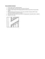
Section 1.1
Important Questions
This attic ladder can be installed in structures with
conventional wood roof frames (See Figure 1). If a
ceiling is present, you must have an attic hole in
the ceiling that allows you to enter the overhead
space for a pre-installation inspection.
Roof support structures that have braces connected
to the ceiling joists or which use trusses (See Figure 2)
cannot be cut without destroying the load-bearing
capacity of that section of the roof. Do not cut joists
that are part of a braced conventional frame or
truss without rst consulting an architect or
structural engineer (see the Yellow Pages under
“Architects or Structural Engineers”).
The attic ladder should not be installed in a ceiling that has any of the following:
– Components of heating/cooling systems embedded in the ceiling
– Joists made of materials other than wood
– Metal reinforced plaster
– Suspended ceilings
If your ceiling contains any of the above, do not attempt to install the attic ladder. Contact a professional for assis-
tance with your specic needs (see the Yellow Pages under “Heating and Cooling Contractors, Building Contractors,
Carpenters, Home Builders, Home Improvements, or Contractors-General”).
Do these instructions meet your needs?
These instructions describe how to install the attic ladder parallel or perpendicular to the ceiling joists. Contact a
professional if you want the attic ladder installed in some other direction relative to the joists.
Is your ceiling and joist structure suitable for this installation?
Ceiling Joist
Rafter
Conventional Roof Frame
Figure 1
Creating a Rough Opening
Appendix
Is your ceiling and joist structure suitable for this installation?
Figure 2
WARNING: DO NOT CUT THESE TYPES OF STRUCTURES WITHOUT
CONSULTING AN ARCHITECT OR STRUCTURAL ENGINEER.
Ceiling Joist
Rafter
Truss Roof Frame
Ceiling Joist
Rafter
Conventional Roof Frame with Braces
Connected to Ceiling Joists
Braces
11

Materials:
– Several pieces of joist-sized lumber (the amount depends on the specic installation)
– 16d sinker nails or screws of equivalent strength (24-60 depending on the specic installation)
– 20d sinker nails or screws of equivalent strength are needed for installations where joists are cut
Stepladder:
– You will need a stepladder that is tall enough so that you can get into the overhead space without
stepping above the working height of the stepladder. The working height of the stepladder is two
steps down from the top.
– Your stepladder must also have a duty rating that is greater than the sum of your weight plus
the weight of the attic ladder and any additional materials used for installation.
CAUTION: Be careful when using a stepladder to climb into and out of the overhead space.
Tools For Creating a Rough Opening:
– Flashlight or extension light
– Claw hammer
– Pencil
– Handsaw/power saw
– Tape measure
– Framing square
– Tools to cut a hole in the existing ceiling
Safety Equipment:
– Gloves
– Safety goggles
– Dust mask
Section 1.2
Tools and Materials Needed
12

Section 1.3
Finding a Suitable Location
Before Proceeding: You must have a suitable ceiling and joist structure, tools and materials needed, and a level and
at location in the ceiling.
Goal: To nd a location free of hazards and obstructions that will provide room for the installation and use of the attic ladder.
STEP 1. Pick a potential location for installation. Check for the size of rough opening shown on the box or in in the
pre-installation checklist.
If you are installing the attic ladder in a garage, don’t forget to consider where cars will be parked.
STEP 2. If there is no ceiling and the attic ladder will
t between the joists so that no joists need
to be cut, go to Section 1.5 “FRAMING
THE ROUGH OPENING”.
If there is no ceiling, but one or more
joists need to be cut, go to Section 1.4
“CUTTING THE CEILING JOISTS”.
If there is a ceiling at this location, you
will need to inspect the attic area
above this location as described in
steps 3 and 4.
STEP 3. Go into the overhead space and nd the area above your chosen location.
This area may be located by:
A) Listening for tapping from below
B) Measuring distances from walls or other objects common to the overhead space and the room below
WARNING: Do not drive metal nails or other conductive objects into the ceiling unless you are sure they will not
contact electric wires. Contact with an electrical wire can be deadly.
STEP 4. At this location in the overhead space:
A) Check that there is enough space for you to safely move around
during installation.
B) Check the overhead space for storage space adjacent to the chosen location. If walking
or crawling in the overhead space is desired, make sure that there is enough room to do so.
C) Check above your chosen location for hazards and obstructions such as:
– Electrical wires
– Pipes
– Heating and cooling ducts
– Furnaces
– Hot water heaters or other obstructions
Note: To check for hazards, you will need to move insulation away from your chosen location.
Wear a dust mask, safety goggles, and gloves and keep your body covered to prevent ne cuts
from berglass. Gently push aside insulation to avoid stirring up dust that may be harmful to your
eyes and lungs.
STEP 5. If any hazards or obstructions are present at your chosen location, look for another location or have
the hazards or obstructions moved by professionals (see the Yellow Pages under “Electrical
Contractors, Heating and Cooling Contractors, and Plumbing Contractors”).
WARNING:
FOR YOUR SAFETY, WATCH OUT FOR OVERHEAD HAZARDS.
DO NOT
stand or sit on the ceiling or insulation cover-
ing the ceiling — the ceiling is not made to support your
weight. You can fall through the ceiling even though it
looks solid! Only the joists can support weight.
Watch out for sharp nails sticking through the roof.
!
13

Before Proceeding: You must have a location that:
A) Is free of hazards and obstructions in the overhead space.
B) Is free of hazards in the ceiling.
C) Provides enough room for installation.
D) Provides enough room to use the attic ladder.
Goal: To cut a hole, that is the correct size, in the ceiling at the desired location.
Section 1.4
Cutting a Hole in the Ceiling
Figure 6
STEP 1. Prepare the room by moving furniture,
covering ooring with a drop cloth and
removing children and pets to a safe
distance.
STEP 2. Put on safety goggles and a dust mask.
These will keep pieces of ceiling particles
and dust from falling into your eyes, mouth
or nose as you make a starter hole and cut
into the ceiling.
STEP 3. With a hammer and chisel, make a starter
hole near the center of the chosen location
(See Figure 4).
STEP 4. Enlarge the opening with a saw until you
can see a joist (See Figure 5).
STEP 5. Draw a rectangle the size of the rough
opening on the ceiling, with one edge
parallel to a joist (See Figure 6). You may do
this by sawing until you reach a joist and use
it as a frame of reference. (The size of the
rough opening must be at least 18" x 24".)
Note: Locating at least one edge of the
opening along a ceiling joist will allow the
joist to be used as a side of the frame you
will build. This will simplify framing the
rough opening.
STEP 6. Cut out the rest of the ceiling within the
marked outline following these instructions:
A) Do not cut any joists at this
time. Cut through the ceiling only.
B) Remove the ceiling in small pieces
because ceiling material can be
very heavy.
STEP 7. If no joists span the hole in the ceiling, go
to Section 1.5 “FRAMING THE ROUGH
OPENING”.
If any joists span the hole, go to Section 1.4
“CUTTING THE CEILING JOISTS”.
Figure 4 Figure 5
WARNING:
DO NOT stand saw, cut, or hammer into the ceiling
until you are sure that the location is free of hazards
and obstructions in the ceiling and attic. Contact with
an electrical wire can be deadly.
!
14

Section 1.4
Cutting a Hole in the Ceiling
STEP 1. If the room has a ceiling and you have cut
the required hole, go to Step 2.
If the room has no ceiling, you will need to
mark the joists according to (A) or (B) below.
(A) If the chosen location is parallel to the
joists, mark the rough opening length on
top of the joists (See Figure 7).
Do not cut the joist at this mark.
(B) If the chosen location is perpendicular to
the joists, mark the rough opening width on
top of the joists (See Figure 8).
Do not cut the joist at this mark.
STEP 2. Cut 2 joist-sized boards long enough to
span 2 joists on each side of your chosen
location (See Figure 9). These boards will
support the joists that will be cut and help
keep the ceiling from sagging or completely
collapsing while you are working in the
overhead space.
STEP 3. Place these boards approximately 24"
from the edge of your chosen location and
nail (See Figure 9).
Note: The 24" distance is needed to
give you room to hammer nails into the
frame that you will build in the next section.
Before Proceeding: You must have either exposed joists or a correctly sized hole at the desired ceiling location.
Goal: To cut out any joists that are in the way of your chosen location. Before cutting the joists, you must attach
them to other joists in the overhead attic to keep the ceiling from sagging or completely collapsing.
Figure 7
Dotted Line Indicates Your Chosen
Location (Location Parallel to Joist).
Figure 8
Dotted Line Indicates Your Chosen
Location (Location Perpendicular to Joist).
Figure 9
Joist Support
Boards
Nail or Screw
Boards to Each Joist
15

Section 1.4 (Continued)
Cutting the Ceiling Joists
STEP 4. Next, determine where the joist(s) should
be cut. Figure 10 shows where to mark the
joist(s) that span your chosen location. Note
that the joist(s) should be marked back
from the edge of your location a distance of
2 times the joist thickness (usually three
inches). This leaves room for two joist-sized
headers to be placed against each end of
the cut joist(s) (See Figure 16 on page 18).
Note: In some homes, especially older
ones, the joists may be slightly thicker than
the lumber you can currently buy. If your
joists have a different thickness than the
lumber you will be using for the headers,
you will need to mark the joists back from
the edge of your location a distance of two
times the header thickness instead of the
joist thickness.
STEP 5. Saw through the joist(s) being careful not to
cut through the ceiling and making sure the
cut ends of the joist(s) are at and vertical.
Figure 10
Dotted
Line Indicates
Your Chosen
Location
2 x Joist
Thickness
2 x Joist
Thickness
Cut
Here
Cut
Here
Section of Joist
to be Removed
Before Proceeding: You should have a space between the joists at least 18". Any cut joists must be attached to uncut
joists.
Goal: To create a four-sided frame the size of the rough opening using joist-sized lumber. This frame will be made of
single or double thickness headers and stringers depending upon the particular installation. The frame is necessary to
support the attic ladder and to reinforce the roof and ceiling structure.
Section 1.5
Framing the Rough Opening
WARNING:
FOR YOUR SAFETY, WATCH OUT FOR OVERHEAD HAZARDS.
DO NOT Do not stand or sit on the ceiling or insulation covering the ceiling — the ceiling is not made to support your
weight. You can fall through the ceiling even though it looks solid! Only the joists can support weight. To avoid falling
through the ceiling, you may want to make a working platform by laying boards across the joist. Watch out for sharp
nails sticking through the roof.
!
16

Section 1.5 (Continued)
Framing the Rough Opening
Installing Headers
If no joists have been cut, go to “Single Headers” below.
If any joists have been cut, go to “Double Headers” on page 18.
Single Headers
STEP 1. Measure the header length “H” between
the joists (See Figure 11).
STEP 2. Cut 2 headers this length. Use
joist-sized lumber.
STEP 3. Place one of these headers at one end of
your chosen location (See Figure 12). The
header must t snugly between the joists.
Hammer it into position if necessary; if it is
more than 1/16" too long, trim it. If it is
more than 1/16" too short, cut another piece.
STEP 4. Square the header to one joist and drive
3 nails (16d) through the joist and into the
header. Check for squareness and drive
3 nails (16d) through the other joist and
into the header (See Figure 12). It is very
important that header board is vertically
square as well as horizontally square to
side joists.
STEP 5. Position the second header at least 24" from
the rst one and repeat Step 4 (See Figure 13).
STEP 6. The frame for the rough opening requires
four sides. The headers make up two of
those sides. If your ceiling joists are spaced
so that they make up the other two sides of
the rough opening, check the opening for
squareness by measuring across the
diagonals. The measurements should be
within 1/8” to be considered square
(See Figure 13).
If your ceiling joists do not make up the
other two sides of the rough opening, you
need to install one or two additional pieces
of lumber to frame the other side(s) of the
rough opening, go to “Installing Stringers”
on page 19.
Figure 11
H
Figure 12
Drive 3 Nails (16d) into
each end of the Header
Nails
Header
Joists
Figure 13 How to check for square
Diagonal
Measurements
Header
Header
Nails
At
least
24"
17

Section 1.5 (Continued)
Framing the Rough Opening
Double Headers
STEP 1. Measure the header length “H” between
the uncut joists (See Figure14).
STEP 2. Cut 4 headers this length. Use joist-sized
lumber.
STEP 3. Place one of these headers against the end
of the cut joist(s) (See Figure 15). It must
t snugly between the uncut joists.
Hammer it into position if necessary; if it is
more than 1/16" too long, trim it. If it
is more than 1/16" too short, cut
another piece.
STEP 4. Square the header to the uncut joist and
nail the header to the end of the cut
joist(s) with 3 nails (See Figure 15).
STEP 5. Check header for squareness then drive
3 nails through each joist into each
end of the header (See Figure 15).
STEP 6. Place a second header against the rst
header and nail it to the rst header with
3 nails between each joist (See Figure 16).
STEP 7. Drive 3 nails through the joists into each
end of the second header (See Figure 16).
STEP 8. Repeat steps 3-7 to install headers at the
opposite end of the opening.
STEP 9. To frame the other side(s) of the rough
opening, go to “Installing Stringers” on page 19.
Cut Joist
First Header
Figure 15
Second Header
Nails
Figure 16
Nails
Figure 14
H
Uncut Joists
18

Section 1.5 (Continued)
Framing the Rough Opening
Installing Stringers
STEP 1. Measure the stringer length “S” between
the headers (See Figure 17).
STEP 2. Cut a stringer to this length. Use
joist-sized lumber.
STEP 3. If the ceiling joist does not provide one side
of the frame, then cut a second stringer the
same length as the rst one. Note that only
one stringer is needed in Figure 17 because
the ceiling joist provides one side of
the frame.
STEP 4. Position the stringer(s) along the unframed
side(s) of your location (See Figure 18).
Check that the inside dimensions of the
frame are at least 18" x 24".
STEP 5. To attach the stringer(s) to the headers, use
nails that are long enough to go through
both headers and into the stringer at least
one inch. In most cases, a 4" nail (20d)
will be long enough. Square the stringer(s)
to the headers at one end and drive 3 nails
through the headers and into the stringer.
Check for squareness, then nail the other
end. Check the rough opening for
squareness by measuring across the
diagonals. The two measurements must
be within 1/8" to be considered square
(See Figure 18).
Note: A 3/4" wood oor 27" min. deep by the full width of
your opening is required for the attachment of the assist
arm. Please refer to Step 5 on page 6 of this manual for
instructions on attaching assist arm.
Figure 18
Figure 17
S
Headers
Stringer
Diagonal
Measurements
Headers
Nails
Support oor for power
assist arm min. 27" by
full width of opening
Full Width
of opening
27"
19
/