Page is loading ...

CAP SCREW
5/16 -18 X 3/4"
BUTTON HD. SOCKET
DRIVER COVER
P/N 11-283397-001
MOUNTING
BASE P/N:
11-363135-001
3/8"
LOCK-
WASHER
SS HEX
HEAD BOLT
3/8-16X
3 INCH
SURFACE
MOUNT
5/16"
LOCK-
WASHER
5/16"
LOCKWASHER
SS SOCKET
HEAD CAP
SCREW
5/16-18X1"
SOCKET CAP
BUTTON HEAD
SCREW
1/4" 20 X 1/2"
CHROME PLATED
GRILLE
P/N 02-0363193-01
SS WASHER
1/4" INTERNAL
TOOTH
DOWN
The word "DOWN"
must be on bottom.
4Unscrew Driver
and remove.
Must be on inside of wire hole.
2Remove screw
and Lockwasher.
Pull off driver
cover.
1Remove 4 cap
screws and washers
then remove grille
Pull wires of
old driver out
bottom.
3Cut power wire
as close to driver
as possible.
Tie wrap
DRIVER
SUB ASSEMBLY
P/N 02-0363155-00
DOWN
BULKHEAD
MOUNT
B
C
D
A
A - 5/16 - 18 SS HEX NUT
B - 5/16" SPLIT LOCKWASHER
C - GASKET (SEAL) P/N 38-0541557-00
P/N 01-0463260-01
D - BUMPER SPACER KIT / OPTIONAL:
(2) spacers
ECUTOR 1
- -
X
TM
©2000 Whelen Engineering Company Inc.
Form No.13526B 081100)
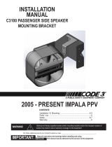
Installation Manual for
ENGINEERING COMPANY INC.
ROUTE 145, WINTHROP ROAD
CHESTER, CONNECTICUT 06412-0684
TELEPHONE: (860) 526-9504
FAX: (860) 526-4078
Driver Replacement:
Siren Speaker
1. Remove the 4 cap screws and lock washers that hold the
grille on then remove the grille.
2. Remove the cap screw and lockwasher that hold on the driver
cover and remove the cover.
3. Cut the power wire coming from the bottom of the driver, as
close to the driver as possible.
4. Pull the old power wires out the bottom, then unscrew the
siren driver in a counter clockwise direction and remove it.
WARNING: When installing the new driver, you must apply Anti-
seize (not supplied) to all threaded parts. Failure to do so will
cause thread galling and void product warranty.
Reassembly: Screw the new driver into the speaker assem-
bly and tighten it firmly being careful not to catch the power wire
between the driver and housing. IMPORTANT: When installing
the new driver, you must be sure the word “DOWN” that is
scribed on the front of the driver is on the bottom of the siren. If
this does not line up when the driver is fully tightened, you will need to loosen the driver and turn the inner horn (See Fig. 4). This
horn has stops to prevent turning during operation and will turn 1/4 turn at a time before it catches on its stops. Now slip the power
wire into the wire hole making sure the tie wrap is on the inside (near the driver) and replace the cover. Once the driver is tightened,
thread the power wires of the new driver into the wire hole and out the base and replace the grille.

SURFACE
MOUNT
Fig. 3
Loud siren noise can cause
hearing loss.
Minimize exposure.
Close windows when using
BOTTOM
VIEW
3"
1.25"
3"
1.75"
3.5"
.437" THRU
(4) PL'CS
1" WIRE
EXIT HOLE
11.84"
DEEP
10.69"
HIGH
15.09
WIDE"
SIDE VIEW
Reach in through
front of siren and
cut wire as close
to siren driver as
possible.
WIRE EXIT
ROUTE
Turn inner horn to adjust
so the word "DOWN" on
the siren driver, is on the
bottom.
Fig. 4
MOUNTING
BASE
10"
5"
7"
3.5"
ù.375
(4) PL'CS
7.75"
3.875"
4.75"
2.375"
9.912"
4.956"
6.92"
3.46"
CUT-OUT
AND REMOVE
THIS AREA
CUT-OUT
AND REMOVE
THIS AREA
CUT-OUT
AND REMOVE
THIS AREA
Fig. 1 GASKET / SEAL
BULKHEAD
MOUNT
(SIDE VIEW)
Extra
Reinforcement
(Optional)
Fig. 2
10.93"
9.970"
MOUNTING SURFACE
7.59"
Bulkhead Mount:
1. Mark the measurements from Fig. 1 onto the mounting area using a scribe or other suitable tool.
2. Drill the 4 mounting holes using an appropriately sized drill, then cut the mounting area out.
3. Slide the siren into the mounting hole from the front of the vehicle, while sliding the 4 mounting boses into the 4 mounting holes. Make sure
that the rubber gasket is properly seated between the siren and mounting surface (Item “C”, on Pg. 1 & Fig. 2 on pg. 2).
4. Secure the siren to the vehicle with the 4 supplied washers and bolts, then run the wires to power, and hookup.
Surface Mount:
1. Using the mounting base as a template, mark off the four mounting holes and wire access hole onto the mounting area, using a scribe or
other suitable tool.
2. Drill the four mounting holes and wire access hole.
3. Now attach the siren to the vehicle as shown, using the supplied Hex head bolts and lock washers. (Fig. 4)
4. Run the wires to power, and hookup.
/