Page is loading ...

User Guide
FOX3 T/R 301
FOX3 T/R 311
Fiber Optic Extenders
Fiber Optic HDMI Transmitters and Receivers
68-2711-01 Rev. A
04 20

Safety Instructions
Safety Instructions • English
WARNING: This symbol, , when used on the product, is intended
to alert the user of the presence of uninsulated dangerous voltage
within the product’s enclosure that may present a risk of electric
shock.
ATTENTION: This symbol, , when used on the product, is intended
to alert the user of important operating and maintenance (servicing)
instructions in the literature provided with the equipment.
For information on safety guidelines, regulatory compliances, EMI/EMF
compatibility, accessibility, and related topics, see the Extron Safety and
Regulatory Compliance Guide, part number 68-290-01, on the Extron
website, www.extron.com.
Sicherheitsanweisungen • Deutsch
WARNUNG: Dieses Symbol auf dem Produkt soll den Benutzer
darauf aufmerksam machen, dass im Inneren des Gehäuses dieses
Produktes gefährliche Spannungen herrschen, die nicht isoliert sind
und die einen elektrischen Schlag verursachen können.
VORSICHT: Dieses Symbol auf dem Produkt soll dem Benutzer in
der im Lieferumfang enthaltenen Dokumentation besonders wichtige
Hinweise zur Bedienung und Wartung (Instandhaltung) geben.
Weitere Informationen über die Sicherheitsrichtlinien, Produkthandhabung,
EMI/EMF-Kompatibilität, Zugänglichkeit und verwandte Themen finden Sie in
den Extron-Richtlinien für Sicherheit und Handhabung (Artikelnummer
68-290-01) auf der Extron-Website, www.extron.com.
Instrucciones de seguridad • Español
ADVERTENCIA: Este símbolo, , cuando se utiliza en el producto,
avisa al usuario de la presencia de voltaje peligroso sin aislar dentro
del producto, lo que puede representar un riesgo de descarga
eléctrica.
ATENCIÓN: Este símbolo, , cuando se utiliza en el producto, avisa
al usuario de la presencia de importantes instrucciones de uso y
mantenimiento recogidas en la documentación proporcionada con el
equipo.
Para obtener información sobre directrices de seguridad, cumplimiento
de normativas, compatibilidad electromagnética, accesibilidad y temas
relacionados, consulte la Guía de cumplimiento de normativas y seguridad
de Extron, referencia 68-290-01, en el sitio Web de Extron, www.extron.com.
Instructions de sécurité • Français
AVERTISSEMENT : Ce pictogramme, , lorsqu’il est utilisé sur le
produit, signale à l’utilisateur la présence à l’intérieur du boîtier du
produit d’une tension électrique dangereuse susceptible de provoquer
un choc électrique.
ATTENTION : Ce pictogramme, , lorsqu’il est utilisé sur le produit,
signale à l’utilisateur des instructions d’utilisation ou de maintenance
importantes qui se trouvent dans la documentation fournie avec le
matériel.
Pour en savoir plus sur les règles de sécurité, la conformité à la
réglementation, la compatibilité EMI/EMF, l’accessibilité, et autres sujets
connexes, lisez les informations de sécurité et de conformité Extron, réf.
68-290-01, sur le site Extron, www.extron.com.
Istruzioni di sicurezza • Italiano
AVVERTENZA: Il simbolo, , se usato sul prodotto, serve ad
avvertire l’utente della presenza di tensione non isolata pericolosa
all’interno del contenitore del prodotto che può costituire un rischio di
scosse elettriche.
ATTENTZIONE: Il simbolo, , se usato sul prodotto, serve ad avvertire
l’utente della presenza di importanti istruzioni di funzionamento e
manutenzione nella documentazione fornita con l’apparecchio.
Per informazioni su parametri di sicurezza, conformità alle normative,
compatibilità EMI/EMF, accessibilità e argomenti simili, fare riferimento
alla Guida alla conformità normativa e di sicurezza di Extron, cod. articolo
68-290-01, sul sito web di Extron, www.extron.com.
I

Copyright
© 2020 Extron Electronics. All rights reserved. www.extron.com
Trademarks
All trademarks mentioned in this guide are the properties of their respective owners.
The following registered trademarks (
®
), registered service marks (
SM
), and trademarks (
TM
) are the property of RGBSystems, Inc. or ExtronElectronics (see the
current list of trademarks on the Terms of Use page at www.extron.com):
Registered Trademarks
(
®
)
Extron, Cable Cubby, ControlScript, CrossPoint, DTP, eBUS, EDID Manager, EDID Minder, Flat Field, FlexOS, Glitch Free, Global
Configurator, GlobalScripter, GlobalViewer, Hideaway, HyperLane, IPIntercom, IPLink, KeyMinder, LinkLicense, LockIt, MediaLink,
MediaPort, NAV, NetPA, PlenumVault, PoleVault, PowerCage, PURE3, Quantum, ShareLink, Show Me, SoundField, SpeedMount,
SpeedSwitch, StudioStation, SystemINTEGRATOR, TeamWork, TouchLink, V-Lock, VideoLounge, VN-Matrix, VoiceLift, WallVault, WindoWall,
XPA, XTP, XTPSystems, and ZipClip
Registered Service Mark
(SM)
: S3 Service Support Solutions
Trademarks
(
™
)
AAP, AFL (Accu-RATEFrameLock), ADSP(Advanced Digital Sync Processing), Auto-Image, AVEdge, CableCover, CDRS(ClassD
Ripple Suppression), Codec Connect, DDSP(Digital Display Sync Processing), DMI (DynamicMotionInterpolation), DriverConfigurator,
DSPConfigurator, DSVP(Digital Sync Validation Processing), eLink, EQIP, Everlast, FastBite, Flex55, FOX, FOXBOX, IP Intercom
HelpDesk, MAAP, MicroDigital, Opti-Torque, PendantConnect, ProDSP, QS-FPC(QuickSwitch Front Panel Controller), RoomAgent,
Scope-Trigger, SIS, SimpleInstructionSet, Skew-Free, SpeedNav, Triple-Action Switching, True4K, True8K, Vector™ 4K, WebShare, XTRA,
and ZipCaddy

FCC Class A Notice
This equipment has been tested and found to comply with the limits for a Class A digital
device, pursuant to part15 of the FCC rules. The ClassA limits provide reasonable
protection against harmful interference when the equipment is operated in a commercial
environment. This equipment generates, uses, and can radiate radio frequency energy and,
if not installed and used in accordance with the instruction manual, may cause harmful
interference to radio communications. Operation of this equipment in a residential area is
likely to cause interference. This interference must be corrected at the expense of the user.
Battery Notice
This product contains a battery. Do not open the unit to replace the battery. If the
battery needs replacing, return the entire unit to Extron (for the correct address, see the
Extron Warranty section on the last page of this guide).
CAUTION: Risk of explosion. Do not replace the battery with an incorrect type. Dispose
of used batteries according to the instructions.
ATTENTION : Risque d’explosion. Ne pas remplacer la pile par le mauvais type de pile.
Débarrassez-vous des piles usagées selon le mode d’emploi.
Class 1 Laser Product
Any service to this product must be carried out by Extron Electronics and its qualified
service personnel.
CAUTION: Using controls, making adjustments, or performing procedures in a manner
other than what is specified herein may result in hazardous radiation exposure.
NOTE: For more information on safety guidelines, regulatory compliances,
EMI/EMF compatibility, accessibility, and related topics, see the “Extron Safety and
Regulatory Compliance Guide” on the Extron website.
Produit laser de classe1
Si ce produit a besoin d’un quelconque entretient, celui-ci doit être fait par
ExtronElectronics et son personnel qualifié.
ATTENTION : L’utilisation de commandes, la réalisation de réglages, ou l’exécution de
procédures de manière contraire aux dispositions établies dans le présent document,
présente un risque d’exposition dangereuse aux radiations.
Remarque : Pour plus d'informations sur les directives de sécurité, les conformités de
régulation, la compatibilité EMI/EMF, l'accessibilité, et les sujets en lien, consultez le
«Informations de sécurité et de conformité Extron» sur le site internet d'Extron.

Conventions Used in this Guide
Notifications
The following notifications are used in this guide:
DANGER:
• Will result in serious injury or death.
• Entraînera des blessures graves ou la mort.
WARNING: Potential risk of severe injury or death.
AVERTISSEMENT : Risque potentiel de blessure grave ou de mort.
CAUTION: Risk of minor personal injury.
ATTENTION : Risque de blessuremineure.
ATTENTION:
• Risk of property damage.
• Risque de dommages matériels.
NOTE: A note draws attention to important information.
TIP: A tip provides a suggestion to make working with the application easier.
Software Commands
Commands are written in the fonts shown here:
^AR Merge Scene,,0p1 scene 1,1 ^B 51 ^W^C.0
[01] R 0004 00300 00400 00800 00600 [02] 35 [17] [03]
E X! *X1&* X2)* X2#* X2! CE}
NOTE: For commands and examples of computer or device responses used in this
guide, the character “0” is the number zero and “O” is the capital letter “o.”
Computer responses and directory paths that do not have variables are written in the font
shown here:
Reply from 208.132.180.48: bytes=32 times=2ms TTL=32
C:\Program Files\Extron
Variables are written in slanted form as shown here:
ping xxx.xxx.xxx.xxx —t
SOH R Data STX Command ETB ETX
Selectable items, such as menu names, menu options, buttons, tabs, and field names are
written in the font shown here:
From the File menu, select New.
Click the OK button.
Specifications Availability
Product specifications are available on the Extron website, www.extron.com.
Extron Glossary of Terms
A glossary of terms is available at http://www.extron.com/technology/glossary.aspx.


viiFOX3 T/R 301/311 Transmitters and Receivers • Contents
Contents
Introduction ................................................1
About this Guide .................................................. 1
Product Description ............................................. 1
Transmitter....................................................... 3
Receiver .......................................................... 3
Both Units ....................................................... 3
System Compatibility ....................................... 3
Fiber Cable Transmission Modes ..................... 4
Extron LinkLicense........................................... 4
Features .............................................................. 4
Installation and Operation............................7
Installation Overview ............................................ 7
Rear Panel Features ............................................ 7
Transmitter Rear Panel Connections ................ 7
Receiver Rear Panel Connections .................. 10
Connector and Cable Details ............................. 13
HDMI Connectors .......................................... 13
Analog Audio Connectors .............................. 14
RS-232, IR, and Sync Connectors ................. 14
TP Cable Termination and
Recommendations ....................................... 15
USB HID and USB 2.0 Connectors ................ 16
Front Panel Features .......................................... 17
Operation .......................................................... 18
Reset ............................................................. 18
Configuration ..................................................... 20
EDID .............................................................. 20
HDCP ............................................................ 20
RS-232 Insertion............................................ 21
Audio Configuration ........................................... 22
Audio Embedding .......................................... 22
Input Audio Gain ............................................ 22
Input Audio .................................................... 22
Output Audio Volume ..................................... 22
Audio Return ................................................. 22
Audio Mute .................................................... 22
SIS Configuration and Control ...................23
Host Control Ports ............................................. 23
Rear Panel RS-232 Port ................................ 23
Front Panel Configuration USB Port ............... 23
Ethernet (LAN) Ports ...................................... 24
Establishing a Connection.............................. 24
Simple Instruction Set Control ........................... 26
Host-to-Unit Instructions ................................ 26
Device-Initiated Power-Up Message .............. 26
Error Responses ............................................ 26
Timeout ......................................................... 27
Using the Command and Response Table ..... 27
Common symbol definitions........................... 28
Command and Response Table for
SIS Commands ................................................ 29
Configuration Software .............................33
Software/Firmware Installation ........................... 33
Connecting to PCS ............................................ 35
Device Discovery Panel .................................. 35
TCP/IP Panel ................................................. 36
Offline Device Preview .................................... 36
Software Overview ............................................. 37
Software Menu .............................................. 38
Device Menu.................................................. 40
Internal Web Page ..................................... 42
Accessing the Internal Web Page ...................... 42
Disabling Compatibility Mode ......................... 43
Web Page Panels .............................................. 43
Device Info Panel ........................................... 43
Device Status Panel ....................................... 44
Network Settings Panel ................................. 45
Firmware Panel .............................................. 45
Roles and Permissions Panel ......................... 46
LinkLicense Panel .......................................... 47
About the FOX3T/R301/311 ........................ 48

FOX3 T/R 301/311 Transmitters and Receivers • Contents viii
Equipment Mounting .................................49
Mounting the Transmitter ................................... 49
Tabletop Use ................................................. 49
Mounting kits ................................................. 49
UL Rack-Mounting Guidelines ....................... 49

FOX3 T/R 301/311 Transmitters and Receivers • Introduction 1
Introduction
WARNING: The FOX3T/R301 and FOX3T/R311 output continuous invisible light
(Class 1 rated), which may be harmful to the eyes; use with caution.
AVERTISSEMENT : Le FOX3T/R301 et FOX3T/R311 émet une lumière invisible en
continu (conforme à la classe1) qui peut être dangereux pour les yeux, à utiliser avec
précaution.
• Do not look into the rear panel fiber optic cable connectors or into the fiber optic
cables themselves.
• Ne regardez pas dans les connecteurs de câble fibre optique sur le panneau arrière
ou dans les câbles fibre optique eux-mêmes.
• Plug the attached dust cap into the optical transceiver when the fiber optic cable is
unplugged.
• Branchez la protection contre la poussière dans l’ensemble émetteur/récepteur
lorsque le câble fibre optique est débranché.
About this Guide
This guide contains information about the Extron FOX3T/R301 and FOX3T/R311 fiber
optic extenders.
Product Description
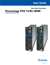
The FOX3T/R301 and FOX3T/R311 Transmitter and Receiver are ultra-high performance
fiber optic extender sets for long haul transmission of the following over two fiber optic
cables (see figure1 on page2):
• Uncompressed or visually lossless HDCP-compliant 4096x2160 or 3840x2160 (UHD)
@60Hz video HDMI video
• 2-CH LPCM audio
• RS-232 and IR control signals
• USB HID (for Human Interface Devices such as keyboards and mice
• USB 2.0 (FOX3T/R301 transmitter and receiver only)
• 3D Sync
The transmitter and receiver extend HDMI signals up to:
• 20 km (12.4 miles) for the singlemode cables
• 500 m (1640 feet) with 50 µm OM4 4700 MHz bandwidth laser optimized multimode
cables
(see Fiber Cable Transmission Modes on page4).

FOX3 T/R 301/311 Transmitters and Receivers • Introduction
2
S
T
A
N
DB
Y
CLASS 2 WI
RI
N
G
1
2
X
PA 1002
LEV
E
L
1
1
2
1
2
L
I
M
I
TE
R
/
P
R
OT
ECT
SI
GNAL
2
I
NP
UTS
OUT
P
UT
R
E
M
OT
E
0
0
V
OL/
M
UT
E
10V
5
0
m
A
1
0
0
-
2
4
0
V
1
.3
A,
5
0
-6
0
Hz
60-60 Hz
100
-240V
~
0.7
A MAX
L
R
L
R
RS-232
Tx Rx
Tx RxG
I
R
A
OUT
R
IN
OUTPUTS
AUDIO
RETURN
INPUTS
CONTROL
B
OUT
IN
USB 2.0
AUDIO
FOX3 R 301
LAN
1
1
2
HDMI
DEVICES
USB HID
100 mA
500 mA
REMOTE
RS-232
Tx Rx
S
5VG
3D
SYNC
60-60 Hz
100-240V
~
0.7A MAX
L
R
L
R
RS-232
Tx
Rx
Tx RxG
IR
A
OUT
R
IN
INPUTS
AUDIO
RETURN
OUTPUTS
CONTROL
B
OUT IN
HDMI
LOOP OUT
USB 2.0
AUDIO
FOX3 T 301
LAN
HOST
HOST
REMOTE
RS-232
Tx
Rx S
5VG
3D
SYNC
USB HID
Ethernet
Ethernet
HDMI
Loop out
HDMI
Output
HDMI Input
Extron
SI 28
Surface-mount
Speakers
Extron
XPA 1002
Power Amplier
4K Display
4K Media Player
Local
Monitor
4K
Up to 20 km (12.43 miles)
Singlemode Fiber
SM Model
Audio
Output
RS-232
Extron
FOX3 T 301
Fiber Optic Transmitter
Extron
FOX3 R 301
Fiber Optic Receiver
LAN
MODE
L
80
POWER
SD CARD
USB
PLAY
STATUS
Figure 1. Typical FOX3T/R301 Transmitter and Receiver Application
1

FOX3 T/R 301/311 Transmitters and Receivers • Introduction
3
Transmitter
The FOX3T301 and FOX3 T 311 transmitters accept HDMI video, at a resolution of up
to 4K (4096x2160 @ 60 Hz). The video input can also include embedded audio. The
transmitter also loops the HDMI input through for a local monitor.
The transmitter can accept an analog audio input on a 5-pole captive screw connector. The
transmitter automatically detects whether embedded audio is present on the HDMI input. If
none is detected, the transmitter selects the analog audio for the unit to embed in the digital
video stream and transmit to the receiver. Audio can be selected via an Simple Instruction
Set (SIS) command or Product Configuration Software (PCS).
The transmitter has an HID USB port (both models) and a USB 2.0 port (FOX3T301)
that connects directly to USB ports on a PC or USB host. The transmitter includes USB
peripheral emulation to enable trouble-free booting of a host computer that is not connected
to a keyboard or mouse.
It also accepts a 3D sync signal.
The transmitter can receive an optional return (receiver-to-transmitter) stream of serial
RS-232 communications from a controlled device, such as projector responses.
The transmitter converts the HDMI video, the selected audio, and the RS-232 serial
communication, one or both USB inputs, and 3D sync into two proprietary data streams
and outputs them as optical signals via fiber optic small form factor pluggable (SFP)
modules on two LC connector to a compatible Extron FOX3 fiber optic receiver. It also can
receive an audio return channel.
The transmitter has a built-in color bars test pattern to assist in setting up the display
equipment.
Receiver
The FOX3R301 and FOX3 R 311 receivers accept proprietary optical signals on one, two,
or up to three LC connectors from a compatible fiber optic FOX3 transmitter. The receiver is
compatible with all Extron FOX3 transmitters.
The receiver outputs HDMI video, digital audio (embedded in the HDMI output), analog
audio, RS-232 and IR commands and data, USB signals, and 3D sync.
The receiver has two HID USB ports (both models) to connect one or two peripheral devices
and a USB 2.0 port (FOX3R301) that connects directly to USB devices.
If the receiver is appropriately configured and has return fiber optic cables installed, it also
can receive RS-232, IR, and USB returns from controlled devices and send them to the
transmitter via a proprietary optical signal.
The video output of the receiver is a lossless HDMI image up to 4K (4096x2160 @ 60 Hz),
including 1080p/60 Hz with Deep Color.
Both Units
The transmitter and receiver have many controls, including audio adjustments, that are
available under Remote RS-232 and USB port Simple Set Instruction (SIS) control and PCS.
Both units have video, audio, fiber light status, and lost-light alarm indicators.
System Compatibility
NOTE: The FOX3 products are not compatible with legacy FOX, FOXBOX, FOX II,
PowerCage 401 FOX, or PowerCage 1600 FOX products.

FOX3 T/R 301/311 Transmitters and Receivers • Introduction
4
Fiber Cable Transmission Modes
The transmitter and receiver are further categorized by the type of fiber optic cable,
multimode or singlemode, which define the effective range of transmission:
Multimode — Long distance, up to 500 m (1640 feet) (depending on the fiber cable)
Singlemode — Very long distance, up to 20 km (12.4 miles)
NOTE: The multimode and singlemode units are physically and functionally identical,
with the exception of the effective range of transmission. In this guide, any reference
applies to either transmission mode unless otherwise specified.
Extron LinkLicense
An Extron LinkLicense unlocks features that add convenience, expand system options, and
enhance the capabilities of Extron products. Each LinkLicense can be purchased separately
from the FOX3 device and activated as the need arises.
LinkLicense upgrades available for the FOX3 transmitter and receiver include the following:
• Uncompressed Video Upgrade —
• This LinkLicense is enabled once and lasts for the life of the product.
• Allows the FOX3 devices to pass uncompressed 4K @ 60 Hz video on the second
SFP module, enabling the highest video performance.
Features
• FOX3 T 301 — Transmits HDMI video, USB HID, USB 2.0, stereo audio, RS-232
control, IR control, and 3D sync signals over fiber optic cabling.
• FOX3 T 311 — Transmits HDMI video, USB HID, stereo audio, RS-232 control, IR
control, and 3D sync signals over fiber optic cabling.
• FOX3 R 301 — Receives HDMI video, USB HID, USB 2.0, stereo audio, RS-232
control, IR control, and 3D sync signals over fiber optic cabling.
• FOX3 R 311 — Receives HDMI video, USB HID, stereo audio, RS-232 control, IR
control, and 3D sync signals over fiber optic cabling.
• Supports mathematically lossless 4K video up to 4096x2160 @ 60 Hz with 4:4:4
chroma sampling over one fiber.
• Supports uncompressed 4K video up to 4096x2160 @ 60 Hz with 4:4:4 chroma
sampling over two fibers.
• Supported HDMI 2.0 specification features include data rates up to 18 Gbps,
Deep Color up to 12 bit, and 3D.
• HDCP 2.
3 compliant
• Device class filtering on USB HID port restricts the range of device types
to HID — Device class filtering prevents unauthorized downloading or uploading of
content via the USB port in secure environments. The USB HID port is configured at the
factory, such that device class filtering cannot be removed or altered in the field.
• Supports USB 2.0 to 1.0 devices and USB 3.0 devices that can operate at USB
2.0 data rates of up to 480 Mbps (FOX3 T/R 301) — Provides USB extension,
allowing connection to peripheral devices over the same fiber optic cable as video and
audio.
• Buffered HDMI input loop-out (FOX3 transmitters) — Local HDMI output provides
signals for a local display, enabling monitoring or sharing of content without the need for
a separate distribution amplifier.

FOX3 T/R 301/311 Transmitters and Receivers • Introduction
5
• HDMI audio de-embedding with analog stereo outputs (FOX3 receivers) —
Digital HDMI audio is made available as a balanced or unbalanced analog stereo signal
on captive screw connectors.
• Key Minder continuously verifies HDCP compliance for quick, reliable
switching — Authenticates and maintains continuous HDCP encryption between
input and output devices to ensure quick and reliable switching in professional AV
environments.
• EDID Minder automatically manages EDID communication between connected
devices (FOX3 transmitters) — EDID Minder ensures that all sources power up
properly and reliably output content for display.
• Audio gain and attenuation adjustment capability (FOX3 transmitters) — Setting
the level of gain or attenuation eliminates noticeable volume differences when switching
between sources.
• Audio embedding (FOX3 transmitters) — Analog stereo audio signals are converted
to digital HDMI audio.
• Analog audio return channel — Provides balanced return analog stereo audio input
to support a remote audio source at the receiver.
• Bidirectional RS-232 and IR signal transmission over fiber optic cabling for AV
device control — Bidirectional RS-232 and IR control pass-through enables a remote
display to be controlled without the need for additional cabling. Two fibers are required
for bidirectional communications.
• User-selectable HDCP authorization (FOX3 transmitters) — Allows the transmitter
to appear HDCP compliant or non HDCP compliant to the connected source.
• HDCP Visual Confirmation (FOX3 receivers) — When HDCP encrypted content is
transmitted to a non HDCP compliant display, a full screen green signal is sent to the
display for immediate visual confirmation that protected content cannot be viewed on
that display.
• Integrated two-port HID hub with 100mA available on each port (FOX3
receivers) — Allows simultaneous connection to multiple peripheral devices, including
keyboards, mice, and other HID - Human Interactive Devices.
• Host emulation on the USB HID ports (FOX3 receivers) — Offers increased system
reliability by emulating a continuous connection between the HID-compliant keyboard
and mouse and a host.
• Peripheral emulation on USB HID port (FOX3 transmitters) — Offers increased
system reliability by emulating a continuous connection between the host and an HID-
compliant keyboard and mouse.
• LinkLicense Support — Extron LinkLicense unlocks features that add convenience,
expand system functionality, and enhance the capabilities of Extron products.
• Front panel USB configuration port — Enables easy system configuration and
firmware upgrading without having to access the rear panel.
• Ethernet monitoring and control — Enables control and proactive monitoring over a
LAN, WAN, or the Internet.
• RS-232 control — Features an RS-232 serial port for control and configuration.
• Real-time status LED indicators for troubleshooting and monitoring — Front and
rear panel LEDs verify signal presence, HDCP authentication, fiber link status, audio,
USB HID, USB 2.0, and power.
• Easy setup and commissioning with Extron PCS - Product Configuration
Software — Conveniently configures multiple products using a single software
application.

FOX3 T/R 301/311 Transmitters and Receivers • Introduction
6
• Internal color bars test pattern for calibration and setup — Simplifies setup and
installation by providing a video signal when a source is unavailable.
• Compatible with Extron FOX3 Series matrix switchers — Creates HDCP-
compliant signal distribution systems.
• JITC Certified — Successfully completed interoperability and information assurance
testing for use in government applications and other mission-critical environments.
• Industry standard LC connectors provide reliable physical connectivity and
precise fiber core alignment
• Available as an 850 nm multimode model for moderate-range transmissions up
to 500 m (1640 feet) and a 1310 nm singlemode model for extreme distances up
to 20 km (12.4 miles).
• 1U high, half rack width metal enclosure
• Internal Extron Everlast power supply — Provides worldwide power compatibility,
with high demonstrated reliability and low power consumption for reduced operating
cost.
• Extron Everlast Power Supply is covered by a 7-year parts and labor warranty

FOX3 T/R 301/311 Transmitters and Receivers • Installation and Operation 7
Installation and
Operation
This section details the installation of the FOX3T/R301/311 transmitter and receiver
system, including:
• Installation Overview
• Rear Panel Features
• Front Panel Features
• Connector and Cable Details
• Operation
Installation Overview
Follow these steps to install and set up an Extron FOX3T/R301/311 transmitter and
receiver system for operation:
c
Turn off all of the equipment. Ensure that the video source and the output display are all
turned off and disconnected from the power source.
c
Mount the transmitter and receiver (see Equipment Mounting on page49).
c
Connect the cables and configure the units (see “Transmitter Rear Panel Connections,”
starting below).
c
Plug in the power supplies, then turn on the display and the input.
Rear Panel Features
Transmitter Rear Panel Connections
NOTE: Figure 2 shows the FOX3T301 transmitter. The FOX3 T 311 looks similar, with
the exception of the USB ports (
E
). It does not have the USB 2.0 port.
60-60 Hz
100-240V
~
0.7A MAX
LR
LR
RS-232
Tx Rx Tx RxG
IR
A
OUT
R
IN
INPUTS
AUDIO
RETURN
OUTPUTS
CONTROL
B
OUTIN
HDMI
LOOP OUT
USB HID
USB 2.0
AUDIO
FOX3 T 301
LAN
HOST HOST
REMOTE
RS-232
Tx Rx S5VG
3D
SYNC
J
E
E
E L
L
LK
K
KJ
J
JB
B
BA
A
A D
D
D
I
I
I
F
F
F
G
G
G
C
C
C H
H
H
Figure 2. FOX3T301 Transmitter Rear Panel Connectors
A
Power inlet
D
Audio input
G
HDMI Loop Out
J
LAN Ethernet port
B
Power LED
E
USB Host ports
H
Remote RS-232/3D Sync port
K
SFP module and LEDs
C
Audio Return
F
HDMI input
I
Control RS-232/IR port
L
Reset button
2

FOX3 T/R 301/311 Transmitters and Receivers • Installation and Operation 8
A
Power inlet (see figure2 on page7) — Plug a standard IEC power cord into this
connector to connect the unit to a 100 VAC to 240 VAC, 50-60 Hz power source.
B
Power LED — The lit LED indicates power is applied and device is ready to transmit.
C
Audio Return — Connect an audio device, such as an amplifier or powered speakers
to this 5-pole, 3.5 mm captive screw connector. This connector outputs returned,
unamplified, line level audio from the receiver (see Analog Audio Connectors on
page14 to wire this connector).
D
Audio input — This 3.5 mm, 5-pole captive screw connector accepts balanced or
unbalanced line level analog audio input that can be transmitted to the receiver (see
Analog Audio Connectors to wire this connector).
E
USB Host ports — (see USB HID and USB 2.0 Connectors on page16)
• USB HID — Connect USB type A to B cables between this USB type B port and
the USB port of a host. The USB HID ports are used only for a mouse or keyboard.
• USB 2.0 (FOX3T301 only) — Connect USB type A to B cables between this USB
type B port and the USB port of a host. The USB 2.0 ports are used for thumb
drives, cameras, keyboards, a mouse, CAC reader, and such devices.
F
HDMI input — Connect a digital video input to this HDMI port. The transmitter
also accepts embedded digital audio on this connector (see HDMI Connectors on
page13 to use the included Extron Lock-It Lacing Bracket).
G
HDMI Loop Out — If desired, connect a local monitor to this HDMI port.
H
Remote RS-232/3D Sync port —
• Remote RS-232 port — For serial control of the transmitter, connect a host
device, such as a computer or touch panel control, via the three left poles
(Tx, Rx, and G) of this 5-pole captive screw connector (see RS-232, IR, and Sync
Connectors on page14 to wire this connector).
• 3D Sync port — For stereoscopic 3D sync, such as external IR emitter for glasses,
connect a PC to the two right poles of the REMOTE RS-232/3D Sync 5-pole
captive screw port on the transmitter (see RS-232, IR, and Sync Connectors to
wire this connector).
I
Control RS-232 and IR port — Connect a serial RS-232 signal, a modulated or
unmodulated IR signal, or both to this 3.5 mm, 5-pole captive screw connector for
bidirectional RS-232 and IR communication (see RS-232, IR, and Sync Connectors
to wire the connector).
NOTES:
• To receive responses from the controlled device over RS-232 or IR, two fiber
optic cables must be connected.
• The FOX3 system can pass RS-232 commands and responses at rates up to
115200 baud.
• RS-232 and IR can be active simultaneously.
J
LAN Ethernet port — Connect the transmitter to an Ethernet LAN or WAN via this
RJ-45 port. Ethernet control allows the operator to configure the transmitter from a
remote location. When connected to an Ethernet LAN or WAN, the transmitter can be
accessed and operated from a computer running a standard Internet browser (see TP
Cable Termination and Recommendations on page15 to wire the connector).
• Link (green) LED — Indicates that the unit is properly connected to an Ethernet
LAN. This LED should light steadily.
• Act (yellow) LED — Indicates transmission of data packets on the RJ-45
connector. This LED should blink as the unit communicates.
NOTE: This is not a pass-through LAN connection

FOX3 T/R 301/311 Transmitters and Receivers • Installation and Operation 9
K
SFP module and LEDs — (see figure2 on page7)
WARNING: The units output continuous invisible light (Class 1 rated), which may be
harmful to the eyes; use with caution. Plug the attached dust cap into the optical
transceiver when the fiber optic cable is unplugged.
AVERTISSEMENT : Le produit émet une lumière invisible en continu (conforme
à la classe1) qui peut être dangereux pour les yeux, à utiliser avec précaution
Branchez la protection contre la poussière dans l’ensemble émetteur/récepteur
lorsque le câble fibre optique est débranché.
NOTES:
• Ensure the proper fiber cables for the transmitter and receiver pair are used.
Typically, singlemode fiber has a yellow jacket and multimode cable has an
orange or aqua jacket.
• See figure3 for fiber cable connections. Connect the transmitter to a receiver in
one of three ways:
• One way (transmitter to receiver) only, connect transmitter Outputs A (
1
) to
receiver Inputs A (
1
).
• Two way (transmitter to receiver and return), connect transmitter Outputs
A (
1
) to receiver Inputs A (
1
) and connect transmitter Outputs A (
2
) to
receiver Inputs A (
2
).
• Output B is available to transmit a 4K @ 60 Hz uncompressed signal when
the FOX3 4K @ 60 Hz Uncompressed Video LinkLicense is purchased.
1
Port A Out (required) — For all one-way video, audio,
and serial communications from the transmitter to the
receiver, connect a fiber optic cable to the Out LC port.
Connect the opposite end of this fiber optic cable to
the Port A In LC port on the receiver (see figure4,
J
on page10) or to any other compatible Extron FOX3
device.
2
Port A In (optional) — For one-way return audio, USB,
and serial communications from the receiver to the
transmitter, connect a fiber optic cable to the In LC port.
Connect the opposite end of this fiber optic cable to the
Port A Out LC port on a receiver (see figure4,
J
) or to
any other compatible Extron FOX3 device.
SFP Link LEDs —
Receiver
T
ransmitter
11
22
22
11
A
OUTIN
OUTPUTS
B
OUTIN
A
OUTIN
INPUTS
B
OUTIN
Figure 3. Connection
• Transmit Optical OUT LED lights solid green when powered and lights off when
there is no power on the endpoint.
• Receive Optical IN LED lights solid green when light is present and lights off when
there is no power or light present.
L
Reset button — Initiates three levels of resets (1, 4, and 5). Use a pointed stylus,
ballpoint pen, or small screwdriver to access the recessed button (see Reset on
page18 for detailed reset information).
3

FOX3 T/R 301/311 Transmitters and Receivers • Installation and Operation 10
Receiver Rear Panel Connections
NOTE: Figure 4 shows the FOX3R301 receiver. The FOX3 R 311 looks similar, with the
exception of the USB ports (
H
). It has no USB 2.0 port.
60-60 Hz
100-240V
~
0.7A MAX
LR
LR
RS-232
Tx Rx Tx RxG
IR
A
OUT
R
IN
OUTPUTS
AUDIO
RETURN
INPUTS
CONTROL
B
OUTIN
USB 2.0
AUDIO
FOX3 R 301
LAN
1
1
2
HDMI
DEVICES
USB HID
100 mA
500 mA
REMOTE
RS-232
Tx Rx S5VG
3D
SYNC
J
EEE KKKJJJIIIBBBAAA DDD HHHCCC FFF GGG
Figure 4. FOX3R301 Receiver Rear Panel Connectors
A
Power inlet
E
USB Hub ports
I
LAN Ethernet port
B
Power LED
F
HDMI output
J
SFP module and LEDs
C
Audio Return
G
Remote RS-232/3D Sync port
K
Reset button
D
Audio output
H
Control RS-232/IR port
A
Power inlet — Plug a standard IEC power cord into this connector to connect the unit
to a 100 VAC to 240 VAC, 50-60 Hz power source.
B
Power LED — The lit LED indicates power is applied.
C
Audio Return — Connect a balanced or unbalanced audio input to this 3.5 mm,
5-pole captive screw connector for return to the transmitter (see Analog Audio
Connectors on page14 to wire this connector).
D
Audio output — This 5-pole, 3.5 mm captive screw connector outputs the transmitted,
unamplified, line level analog audio (see Analog Audio Connectors to wire this
connector).
NOTE: If embedded digital audio is present on the HDMI output, these analog audio
connectors do not output audio unless forced to so by an SIS command (see
Input audio selection on page31).
E
USB Hub ports — (see USB HID and USB 2.0 Connectors on page16)
• USB HID — Connect USB type A to B cables between this USB type B port
and the USB port of a device. The USB HID ports are used only for a mouse or
keyboard.
• USB 2.0 (FOX3R301 only) — Connect USB type A to B cables between this USB
type B port and the USB port of a device. The USB 2.0 ports are used for thumb
drives, cameras, keyboards, a mouse, CAC reader, and such devices.
F
HDMI output — Connect a video display to this HDMI output port with a maximum
resolution of 4096x2160 @ 60 Hz, 8-bit, 4:4:4 chroma sampling (see HDMI
Connectors on page13 to use the included Extron Lock-It Lacing Bracket).
4

FOX3 T/R 301/311 Transmitters and Receivers • Installation and Operation 11
G
Remote RS-232/3D Sync port — (see figure4 on page10)
• Remote RS-232 port — For serial control of the receiver, connect a host device,
such as a computer or touch panel control, via the three left poles (Tx, Rx, and G)
of this 5-pole captive screw connector (see RS-232, IR, and Sync Connectors on
page14 to wire this connector).
• 3D Sync port — For stereoscopic 3D sync, such as external IR emitter for glasses,
connect a PC to the two right poles of the REMOTE RS-232/3D Sync 5-pole
captive screw port on the receiver (see RS-232, IR, and Sync Connectors to wire
this connector).
H
Control RS-232/IR port — Connect a serial RS-232 signal, a modulated or
unmodulated IR signal, or both to this 3.5 mm, 5-pole captive screw connector for
bidirectional RS-232 and IR communication (see RS-232, IR, and Sync Connectors
on page14 to wire the connector).
NOTES:
• If only one fiber optic cable is connected (see figure5 on page12),
RS-232 or IR reports from the controlled device cannot be recieved. To
receive responses from the controlled device, two fiber optic cables must be
connected.
• The transmitter can pass RS-232 commands and responses at rates up to
115200 baud.
I
LAN Ethernet port — If desired, connect the receiver to an Ethernet LAN or WAN via
this RJ-45 connector. Ethernet control allows the operator to control the receiver from
a remote location. When connected to an Ethernet LAN or WAN, the receiver can be
accessed and operated from a computer running a standard Internet browser (see TP
Cable Termination and Recommendations on page15 to wire the connector).
• Link (green) LED — Indicates that the unit is properly connected to an Ethernet
LAN. This LED should light steadily.
• Act (yellow) LED — Indicates transmission of data packets on the RJ-45
connector. This LED should blink as the unit communicates.

FOX3 T/R 301/311 Transmitters and Receivers • Installation and Operation 12
J
SFP module and LEDs —
WARNING: The devices output continuous invisible light (Class 1 rated), which
may be harmful to the eyes; use with caution. Plug the attached dust cap into the
optical transceiver when the fiber optic cable is unplugged.
AVERTISSEMENT : Le produit émet une lumière invisible en continu (conforme
à la classe1) qui peut être dangereux pour les yeux, à utiliser avec précaution
Branchez la protection contre la poussière dans l’ensemble émetteur/récepteur
lorsque le câble fibre optique est débranché.
NOTES:
• Ensure the proper fiber cables for the transmitter and receiver pair are used.
Typically, singlemode fiber has a yellow jacket and multimode cable has an
orange or aqua jacket.
• See figure5 for fiber cable connections. Connect the transmitter to a receiver in
one of three ways:
• One way (transmitter to receiver) only, connect transmitter Outputs A (
1
) to
receiver Inputs A (
1
).
• Two way (transmitter to receiver and return), connect transmitter Outputs
A (
1
) to receiver Inputs A (
1
) and connect transmitter Outputs A (
2
) to
receiver Inputs A (
2
).
• Output B is available to transmit a 4K @ 60 Hz uncompressed signal when
the FOX3 4K @ 60 Hz Uncompressed Video LinkLicense is purchased.
1
Port A Out (required) — For all one-way video, audio,
and serial communications from the transmitter to the
receiver, connect a fiber optic cable to the Out LC port.
Connect the opposite end of this fiber optic cable to
the Port A In LC port on the receiver (see figure4,
J
on page10) or to any other compatible Extron FOX3
device.
2
Port A In (optional) — For one-way return audio, USB,
and serial communications from the receiver to the
transmitter, connect a fiber optic cable to the In LC port.
Connect the opposite end of this fiber optic cable to the
Port A Out LC port on a receiver (see figure4,
J
) or to
any other compatible Extron FOX3 device.
• Transmit Optical OUT LED lights solid green when
powered and lights off when there is no power on the
endpoint.
• Receive Optical IN LED lights solid green when light is
present and lights off when there is no power or light
present.
Receiver
T
ransmitter
11
22
22
11
A
OUTIN
OUTPUTS
B
OUTIN
A
OUTIN
INPUTS
B
OUTIN
Figure 5. Fiber
Cable
Connection
K
Reset button (see figure4 on page10) — Initiates three levels of resets (1, 4, and
5). Use a pointed stylus, ballpoint pen, or small screwdriver to access the recessed
button (see Reset on page18 for detailed reset information).
5
/