Page is loading ...

1
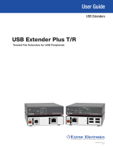
USB Extenders • Setup Guide
USB USB
HUB
1
2
3
4
POWER
12V
1.0A MAX.
LINK
DO NOT
CONNECT
TO LAN
HOST
POWER
12V
0.4A MAX.
DO NOT
CONNECT
TO LAN
LINK
Ground
+12 VDC
External
Power Supply
(12 VDC, 1 A )
Ground
+12 VDC
External
Power Supply
(12 VDC, 1 A )
Keyboard
Laptop
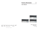
Four USB 2.0 compatible type A female
connectors provide +5 VDC at up to
500 mA to connected USB peripherals.
If the USB host is capable of supplying power,
a transmitter power supply is not required.
The receiver must have a power supply connected.
Transmitter Receiver
UTP or STP CAT5 or better cable:
Te rminate both ends identically, in accordance with
either the TIA/EIA T 568A or the TIA/EIA T 568B
wiring standard.
Run All Cables
Connect the transmitter and receiver as shown above. Do not connect AC power at this time.
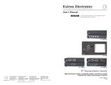
NOTE: The host and hub connectors of the AAP and decorator-style models are on the front panel. The host connection on
the AAP and decorator-style transmitter is a female mini USBType B. Connection and operation are the same as the rack
mount Tx/Rx models.
This guide provides basic instructions for an experienced technician to install and operate the Extron USB Extenders. The USB
Extender Series includes the USB Extender Tx/Rx, AAP Tx/Rx, and D (decorator-style) Tx/Rx. They are USB transmitter and
receiver pairs that extend the usable distance of USB1.0, 1.1, and 2.0 standards with data transfer rates up to 480 Mbp and data
transmission up to 450ft (135m) with standard Category5/5e/6/6e/7 cable.
The rack mountable Tx/Rx, AAPmountableTx/Rx, and D (decorator-style)Tx/Rx models can be mixed.
Mount the USB Extenders
The USB Extender series includes transmitters and receivers in three form factors to provide a variety of mounting options
including:
• USB Extender Tx/Rx in quarter rack width, 3 inch deep, 1 inch high metal enclosures
• USB Extender AAP Tx/Rx for double-space Architectural Adapter Plate openings
• USB Extender D (decorator-style) Tx/Rx for one-gang wall box or mud ring mounting
Choose the appropriate mounting location and install the USB Extender transmitter and receiver following instructions supplied
with the mounting kit. If the rear panel connectors will be covered after mounting, make all connections prior to permanently
mounting a USBExtender.

2
68-1719-50 Rev. F
04 17
USB
CAT 5/5e/6/7
up to 450' (135m)
HUB
1
2
3
4
POWER
12V
1.0A MAX
LINK
DO NOT
CONNECT
TO LAN
HOST
POWER
12V
0.4A MAX
DO NOT
CONNECT
TO LAN
LINK
50/60Hz
100-240V .5A MAX
RS-232
RS-232
KEYBOARD
MOUSE
USB
RESET
LAN
RGB/R-Y,Y,B-Y
RGB/R-Y,Y,B-Y
R/
R-Y
B/
B-Y
H V
S
G/
Y
HDSDI/
SDI
RGB/R-Y, Y, B-Y
4 5 7
6
3
1
2
R/
R-Y
G/Y
VID
H/HV V CR-Y
B/C
B-Y
B-Y
/C
VID
/Y
VID
/Y
O
U
T
P
U
T
S
I
N
P
U
T
S
DVI-D
MTP
DVI
OUT
Extron
Annotator
Annotation Graphics
Processor
Projector/Display
USB Touchscreen
Display
USB
Extron
USB Extender TX
Twisted Pair Transmitter
for USB Peripherals
Extron
USB Extender RX
Twisted Pair Receiver
for USB Peripherals
HOST
USB EXTENDER AAP Tx
ACTIVITY
LINK HOST
USB EXTENDER AAP Rx
HUBACTIVITY
LINK
1
2
1
HOST
2
3
4
3
4
LINK
HOST
ACTIVITY
LINK
ACTIVITY
1
HOST
2
3
4
USB Extender Rx
USB Extender Tx
Transmitters
Receivers
USB Extender Tx D
USB Extender Rx D
A B C
D
A B C
B
C
D
A
B
C
A B C
A
B
C
Apply Power to the USB Extenders
1. Connect AC power to the external power supply for the receiver. The power LED (
A
) on the receiver lights when power is
applied.
2. Connect power to the transmitter depending upon the power source.
• If using an external supply the power LED (
A
) of the transmitter lights when AC power is properly applied. The Link LED
(
B
) on both the transmitter and receiver also lights to indicate proper link cable connection, or
• If using a computer USB port to power the transmitter, the transmitter Power and Link LEDs do not light until after the
laptop or PC is powered and booted up. The receiver Link LED lights once the transmitter is powered.
Connect the Host (Transmitter)
1. Connect a USB cable from the PC or laptop USB port to the transmitter
Host port as shown on the previous page. The AAP and D (decorator-
style) transmitters have a female miniUSBTypeB connector on the
front panel for this connection.
2. Reboot or power up the PC or laptop. The Host LED on the front panel
of the transmitter (
C
) lights when the PC recognizes the port. If the PC
is supplying transmitter power, the transmitter and receiver Link LEDs
(
B
) both light.
Connect the Hub (Receiver)
1. Connect up to four USB cables from peripheral devices to the receiver
Hub ports. The order of connection does not matter.
The Host LED on the receiver (
C
) lights as communications between
the USB transmitter and host occur.
2. As each peripheral is connected, the LED for the appropriate hub port
(
D
) lights when the PC has detected the device.
NOTE: The USB Extender receivers can supply up to 0.5 A to each
connected peripheral.
NOTE: Some USB devices may cause
an inrush current that exceeds the USB
limit of 500 mA to the receiver of the
extenders. In this case, you may need
to connect the USB device to two if the
receiver Hub ports using a USB Y cable
to ensure that the peripheral device
operates properly.
Extron Headquarters
+800.633.9876 Inside USA/Canada Only
Extron USA - West Extron USA - East
+1.714.491.1500 +1.919.850.1000
+1.714.491.1517 FAX +1.919.850.1001 FAX
Extron Europe
+800.3987.6673
Inside Europe Only
+31.33.453.4040
+31.33.453.4050 FAX
Extron Asia
+65.6383.4400
+65.6383.4664 FAX
Extron Japan
+81.3.3511.7655
+81.3.3511.7656 FAX
Extron China
+86.21.3760.1568
+86.21.3760.1566 FAX
Extron Middle East
+971.4.299.1800
+971.4.299.1880 FAX
Extron Australia
+61.8.8113.6800
+61.8.8351.2511 FAX
Extron India
1800.3070.3777
(Inside India Only)
+91.80.3055.3777
+91.80.3055.3737 FAX
© 2017 Extron Electronics All rights reserved. All trademarks mentioned are the property of their respective owners. www.extron.com
/