Page is loading ...

User & Operator Manual
M07716
Issue 2 January 2023
Portable Single Gas Detector
Clip SGD

Navigation
Main navigation
Next and previous
navigation
Click on any button to go to the page.
Page navigation
Click on any page
number go to the page.
Display previous page
Display next page
Print document
Press the Esc key
to display normal
Acrobat© Controls
2
© 2023 Crowcon Detection Instruments Limited
Clip SDG
Prologue
Event Log
Activation
Diagrams
& LCD
Calibration
Mode
Specications
Self Test &
Bump Test
Appendices
Certicates
Warranty
Contents

3
© 2023 Crowcon Detection Instruments Limited
Clip SDG
ContentsContents
Prologue 3
1. Diagram and LCD 4
2. Activation 5
3. Mode 6
3.1 Gas Measurement Mode 6
3.2 Display Device Settings 6
3.3 Alarms and Alerts 7
Default Alarm Set Point 8
4. Event Log 8
5. Calibration 9
5.1 Fresh Air Calibration 9
5.2 Standard Gas Calibration 10
5.3 Return to Gas Measurement Mode 10
6. Specication 11
7. Self Test and Bump Test 12
7.1 Self Test 12
7.2 Bump Test 13
8. Certicates 14
Appendix 1 15
Appendix 2 19
File 19
Tools 19
Help 19
9. Warranty 21
9.1 Limited Warranty 21
Warranty Procedure 21
9.2 Warranty Disclaimer 21
Prologue
Event Log
Activation
Diagrams
& LCD
Calibration
Mode
Specications
Self Test &
Bump Test
Appendices
Certicates
Warranty
Contents

4
© 2023 Crowcon Detection Instruments Limited
Clip SDG
Prologue
WARNING
• Clip SGD is a hazardous area certied gas detector and as such must be operated and maintained in strict accordance
with the instructions, warnings and label information included in the manual.
• Before operating this device, please read carefully and understand all instructions in the manual.
• Understand the screen display and alarm warnings prior to use.
• Before use, please check the activation date, and if the activation date has expired please do not use the device.
• Before use ensure that the device is in good condition and the enclosure, the display window, alarm LED windows and
sounder aperture are undamaged and clear from contaminants.
• Before use perform the self-test of the LED’s, sounder and vibrator.
• Bump test the device regularly by applying a gas concentration exceeding the alarm set point. It is recommended that a
bump test is performed at least every 90 days.
• For the O2 detector perform a calibration every 30 days in a fresh air environment.
• If the device fails a bump test, calibration or self-test please do not use the device.
• Do not disassemble or substitute components, or operate beyond the intended range of use as this may impair intrinsic
safety, invalidate safety certication and will void the warranty.
• Do not attempt to replace the battery or sensor as the Clip SGD is designed to be maintenance free and disposable.
Changing the battery or sensor may impair intrinsic safety, invalidate safety certication and will void the warranty.
• Use IR communications only in a safe area that is free from hazardous gases
• To prevent the generation of static electricity do not clean or rub the LCD screen of the device with a dry cloth or hands in a
hazardous area environment
• Perform cleaning and maintenance of the device in a safe area only that is free from hazardous gases.
• The Clip SGD is shipped with default alarm level settings. It is the users responsibility to ensure the alarm level settings are
appropriate for the specic application; these can be changed as required via the IR_ Link _PC Software.
• Gas concentration measurements by the sensor can vary based on the environment (temperature, pressure and humidity).
Therefore calibration of Clip SGD should be performed in the same (or similar) environment of the device’s actual use.
• Severe vibration or shock to the device may cause a sudden gas reading change. Please use Clip SGD after the value of
gas concentration has stabilized.
• Excessive shock to Clip SGD can cause the device and/or sensor to malfunction.
• If the temperature changes sharply during use of the device (for example moving from indoors to outdoors), the value of
the measured gas concentration can suddenly change. Please use the Clip SGD after the gas concentration value has
stabilized.
• The device is intended for use in normal atmospheric conditions, pressure 80 kPa (0.8 bar) to 110 kPa (1.1 bar); and air with
normal oxygen content, typically 21 % v/v (volume/ volume).
CAUTION
• This device is not a measurement device, but a gas detector.
• Clean detectors with a soft cloth and do not use chemical substances for cleaning.
• To ensure a 24 months battery life is attained it is important to avoid the following activities as this will deplete the battery
lifetime to less than 24 months.
1. Allowing the detector to be in gas alarm frequently or for prolonged periods (Normal Alarm Use: No more than 4
minutes alarm time per day)
2. Operating the detector user button frequently.
3. Connecting the detector with the Clip SGD IR Link frequently, except for regular bump testing.
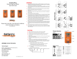
View a serial number on the label at the back side of the device. (ex, 20170101)
1. The serial number indicates below.
01(Months) 2017(Year)
0010101SG
ex) 01(Day) 001(Manufacture Order)
Prologue
Event Log
Activation
Diagrams
& LCD
Calibration
Mode
Specications
Self Test &
Bump Test
Appendices
Certicates
Warranty
Contents

5
© 2023 Crowcon Detection Instruments Limited
Clip SDG
1. Diagram and LCD
IR PortAlarm LED
Alarm LED Alarm LED
Button
Gas Sensor
Gas Type
Buzzer
LCD Display
LCD display symbols
Alarm condition Months remaining
Low alarm Days remaining
High alarm Time remaining (hours)
Test success Maximum peak value
MAX
MIN
Test failure Minimum peak value
% LEL
PPM
%VOL
Fresh air calibration Measurement Unit
Standard gas calibration Low battery life
(Less than 30 days)
Prologue
Event Log
Activation
Diagrams
& LCD
Calibration
Mode
Specications
Self Test &
Bump Test
Appendices
Certicates
Warranty
Contents

6
© 2023 Crowcon Detection Instruments Limited
Clip SDG
2. Activation
Before use, check the activate by date on the box. If the activation date is past, do not activate the device.
Shelf Life within 6 months from manufacture.
Only activate in a safe environment. Press the button for 3 secs; gas type and rmware version (e.g. v2.2) will be displayed.
Following the 10 secs countdown, the device will be fully activated, the icon will ash on the display screen and the device
will be in Gas Measurement mode.
After turning on the device, the remaining life is displayed; 23 months originally. After the remaining life reaches 1 month, 30
days remaining is displayed. When 1 day is left, 24 hours remaining is displayed.
In the event that activation of the device fails, the icon will appear on the display and Gas Measurement mode will not be
entered. In this case, perform calibration or contact authorized reseller or Crowcon Detection Instruments customer support at
+44 (0) 1235 557711 for repair/return information.
Appropriate calibration of the device is required prior to operation. Always ensure that the device responds
correctly to the relevant gas. Verify that foreign materials that could interfere with the detection of gas are
not blocking the sensor.
To avoid radio frequency interference with the detector, it is recommended that any 2-way radios and other
radio frequency emitter devices are kept 30cm away from the Clip device while in use.
Prologue
Event Log
Activation
Diagrams
& LCD
Calibration
Mode
Specications
Self Test &
Bump Test
Appendices
Certicates
Warranty
Contents

7
© 2023 Crowcon Detection Instruments Limited
Clip SDG
3. Mode
3.1 Gas Measurement Mode
Following activation the device will operate in Gas Measurement Mode.
The remaining sensor life (default setting) or gas concentration (congurable option) will be displayed on the screen.
Oxygen concentration is displayed in percent by volume (%Vol) and toxic concentration is displayed in parts per million (PPM).
3.2 Display Device Settings
In Gas Measurement Mode to view the device settings press the button to cycle through the settings. The settings will be
displayed in the following order upon each button press.
Detection mode
Remaining life
( , , )
Min level seen
(only for oxygen)
1st alarm set
point
Max level seen
2nd alarm set
point
Clear min/max
levels
Firmware version Calibration
concentration
Prologue
Event Log
Activation
Diagrams
& LCD
Calibration
Mode
Specications
Self Test &
Bump Test
Appendices
Certicates
Warranty
Contents

8
© 2023 Crowcon Detection Instruments Limited
Clip SDG
3.3 Alarms and Alerts
When a gas concentration exceeds the congured alarm set points, or will be displayed on the screen, the device
will vibrate, alarm LEDs will ash, and the buzzer will sound. The alarms will stop when the device is moved to a clean air
environment.
The table below shows the ‘alarms’ and ‘alerts’ that may be shown on the display during operation.
Alarm Alarm Standard Shown on LCD
Display
Alarm and Vibration Display
Low Alarm Exceeds 1st Alarm
set point icon & concentration
Buzzer, LED
Vibration
High Alarm Exceeds 2nd Alarm
set point icon & concentration
Buzzer, LED
Vibration
Remaining life Below 30 days icon
Lifetime expiration Past 24 months Service life is over
(Replace with a new Clip SGD)
Test failure Failure of sensor
test / calibration
Display beeping
icon with beeping
Battery test Low power
Bump test Bump test period Press the push button to turn off the alarm
Calibration Calibration period Press the push button to turn off the alarm
Default alarm set points are based on common international standards. It is user responsibility to ensure
the congured alarm set points are in accordance with local regulations and site procedures.
Prologue
Event Log
Activation
Diagrams
& LCD
Calibration
Mode
Specications
Self Test &
Bump Test
Appendices
Certicates
Warranty
Contents

9
© 2023 Crowcon Detection Instruments Limited
Clip SDG
Default Alarm Set Point
Gas Type CO H2S O2
Part Number CL-C-25 CL-C-30 CL-C-35 CL-H-2 CL-H-5 CL-H-10 CL-O-19 CL-O-19.5
Lower Alarm Level 25ppm 30ppm 35ppm 2ppm 5ppm 10ppm 19% 19.5%
Upper Alarm Level 50ppm 100ppm 50ppm 5ppm 10ppm 15ppm 23.5% 23.5%
4. Event Log
The last 30 events are stored on a device. Once 30 events are stored, the log events are removed automatically in the order
starting at Event 1. The stored log events can be downloaded using the IR Link or the Docking Station (refer to Appendix 1 and
2). Each alarm event records the following:
• Alarm type (1st or 2nd)
• Alarm concentration in ppm or %
• Peak concentration
Event Log
Prologue
Event Log
Activation
Diagrams
& LCD
Calibration
Mode
Specications
Self Test &
Bump Test
Appendices
Certicates
Warranty
Contents

10
© 2023 Crowcon Detection Instruments Limited
Clip SDG
5. Calibration
For O2 units only. Initial calibration is performed on all devices prior to shipment. Once received, calibration
should be performed monthly (or quarterly) depending on frequency of use.
Fresh Air Calibration
Standard Gas Calibration
5.1 Fresh Air Calibration
Calibration should be performed in a fresh-air environment that is free from the inuence of other gases
(calibration is assumed to be performed in an environment with a concentration of 20.9% oxygen). It is also
recommended that calibration should not be performed in a conned space.
To perform a Fresh Air Calibration press the button to navigate to Calibration Mode, the calibration icon will be displayed on the
screen .
▶Press and hold the button for 5 seconds, ‘CAL’ and the fresh air calibration icon will be seen on the screen .
▶Press and hold the button for 3 seconds to initiate the Fresh Air Calibration.
When the calibration begins, a countdown (starting at 10) will be displayed on the screen.
▶Press ESC to show Gas Measurement mode.
▶Once completed, icon will appear on the LCD.
▶If calibration fails, icon will appear on the display. If this continues, please contact the sales representative or Crowcon
customer support.
Prologue
Event Log
Activation
Diagrams
& LCD
Calibration
Mode
Specications
Self Test &
Bump Test
Appendices
Certicates
Warranty
Contents

11
© 2023 Crowcon Detection Instruments Limited
Clip SDG
5.2 Standard Gas Calibration
To perform a Standard Gas Calibration, using the supplied calibration cap connect the appropriate gas cylinder to the device.
▶Press the button to navigate to Calibration Mode, the calibration icon will be shown, .
▶Press and hold the button for 5 seconds, ‘CAL’ and the fresh air calibration icon will be displayed on the screen, .
▶Press the button once until the calibration icon is shown, .
▶Press and hold the button for 3 seconds to initiate the Standard Calibration. When the calibration begins, a countdown (60
seconds or more depending on the gas type) will appear on the screen.
▶Once completed, icon will appear for several seconds on the display. The device will then return to Gas Measurement
mode.
▶If calibration fails, icon will appear on the display.
▶If this continues, please contact the authorised reseller or the Crowcon customer support team.
5.3 Return to Gas Measurement Mode
To return to Gas Measurement Mode from Calibration Mode, press the button to cycle through the Fresh Air Calibration and
Standard Calibration screens until ‘ESC’ is shown on the display.
Whilst ‘ESC’ is shown on the display press and hold the button for 3 seconds, the device will return to the Gas Measurement
screen.
Gas Type O2Co H2S
Concentration 18%Vol 100ppm 25ppm
Prologue
Event Log
Activation
Diagrams
& LCD
Calibration
Mode
Specications
Self Test &
Bump Test
Appendices
Certicates
Warranty
Contents

12
© 2023 Crowcon Detection Instruments Limited
Clip SDG
6. Specication
Model Clip SGD
Measure Gas O2CO H2S
Sensor range 0-30%Vol 0-300ppm 0-100ppm
Sensor Type Electrochemical
Measurement Diffusion type
Display LCD display
Audible 90dB at 10cm
Warning Lamp Red Flashing LEDs (Light-Emitting Diode)
Vibration Vibration Alarm
Battery Manufacture: Vitzrocell / P/N: SB-AA02(P) / System: Lithium Primary Battery
Nominal voltage: 3.6V / Nominal capacity: 1.2Ah
Temperature & Humidity -30°C to +50°C (-86oF to +122oF) 15% to 90% RH (non-condensing)
Ingress protection IP65 and IP67
Case Rubber Enclosure
Accessories Calibration cap, manual, calibration and test certicate
Option IR Link, Docking Station
Size & Weight Size: 54mm(W) x 91mm(H) x 32mm(D)
Weight: 93g (Toxic), 104g (O2) (Battery, clip included)
Operating Life 24 months, based on 4 minutes of alarm per day (>2900 Alarm minutes)
Event Log Recent 30 alarms
Approval See Certication
Prologue
Event Log
Activation
Diagrams
& LCD
Calibration
Mode
Specications
Self Test &
Bump Test
Appendices
Certicates
Warranty
Contents

13
© 2023 Crowcon Detection Instruments Limited
Clip SDG
7. Self Test and Bump Test
7.1 Self Test
The Clip SGD provides a Self Test function.
The default interval of the Self Test reminder is 20hrs.
Use the IR Link or Docking Station to congure the interval between 1hr and 20hrs, or set to “off”.
When the congured Self Test is due, “STS” will ash on the screen (the message will continue to ash until the user performs a
successful Self Test).
▶Press the button to initiate the Self Test function.
The device will perform a self test by operating the buzzer, LED’s, vibrator and LCD. It will also show the congured low and
high alarm set points on the display.
After the test is completed, “END” will be displayed on the screen. (The user is required to check that the items operated in the
self test, performed as expected).
Prologue
Event Log
Activation
Diagrams
& LCD
Calibration
Mode
Specications
Self Test &
Bump Test
Appendices
Certicates
Warranty
Contents

14
© 2023 Crowcon Detection Instruments Limited
Clip SDG
7.2 Bump Test
The device can be congured to provide an on screen Bump Test reminder.
The default setting for the Bump Test reminder is “off”, no Bump Test reminder will be displayed.
If a Bump Test reminder interval is required it can be congured using the IR Link or Docking Station. The interval can be
congured from 1 day to 365 days.
When congured and a Bump Test is due, the “bts” message be displayed and will ash on the screen.
▶Press and hold the button for 3 seconds, and the “tst” message will be displayed for 45 seconds (to cancel, press the button
for one second).
▶Apply the gas using the calibration cap and gas tube within the 45 second period. If a Bump Test is not undertaken within
this period the “bts” message will ash until a successful test is conducted.
After the selected gas is applied and if the test is successful, the “SUC” message with the icon will be displayed for 3
seconds then immediately return to Gas Measurement Mode. The calibration cap and gas tube can then be removed.
If the test fails, the “FA” message with icon will be displayed and “bts” message will ash until a successful test is conducted.
Prologue
Event Log
Activation
Diagrams
& LCD
Calibration
Mode
Specications
Self Test &
Bump Test
Appendices
Certicates
Warranty
Contents

15
© 2023 Crowcon Detection Instruments Limited
Clip SDG
8. Certicates
IECEx: Ex ia IIC T4 Ga 1: Explosion protected
2: Protection Concept 3: Gas Group
4: Temperature Classication
5: Equipment protection level
Ex ia IIC T4 Ga
Class I, Zone 0, AEx ia IIC T4 Ga
Class I, Division 1, Groups A, B, C, D, T4
ATEX: II 1 G Ex ia IIC T4 Ga KRH 17 ATEX 0013
Directive 2014/34/EU
Standards The electrical apparatus and any acceptable variations to it specied in the schedule of this
certicate and the identied documents, was found to comply with the following standards:
IEC 60079-0:2011 Ed6
IEC 60079-11:2011 Ed6
UL 61010-1,Ed. 3
UL 913, Ed. 8
UL 60079-0, Ed. 6
UL 60079-11, Ed. 6
C22.2 No. 60079-0:2015
C22.2 No. 60079-11:2014
C22.2 No. 61010-1-12:2012
EN 60079-0:2012+A11:2013
EN60079-11:2012
Compliance Electromagnetic Compatibility Directive 2014/30/EU
Manufacturing Approval: The detector manufacturer is certied compliant with ISO 9001:2000 provisions
Prologue
Event Log
Activation
Diagrams
& LCD
Calibration
Mode
Specications
Self Test &
Bump Test
Appendices
Certicates
Warranty
Contents

16
© 2023 Crowcon Detection Instruments Limited
Clip SDG
Appendix 1
Clip SGD Docking Station User Manual
Clip SGD Docking Station Conguration
Users can change settings, upgrade rmware, and download log events through the Docking Station IR link (see Appendix 2)
2
1
3
Figure 1: Clip SGD Dock PC Application
IR / USB Disk
Chose either IR Link or USB Stick to transfer conguration to and from Docking Station.
•Click ‘IR’ 1 to congure Docking Station via the Clip SGD IR Link.
•Click ‘USB Disk’ 2 to select USB Stick connected to PC and transfer conguration to the USB Stick – this can then be inserted
into the Docking Station and the conguration uploaded.
•Info Read/Write: Select to ‘Read’ or ‘Write’ conguration 3 to Docking Station via IR link or to USB Stick
Prologue
Event Log
Activation
Diagrams
& LCD
Calibration
Mode
Specications
Self Test &
Bump Test
Appendices
Certicates
Warranty
Contents

17
© 2023 Crowcon Detection Instruments Limited
Clip SDG
Docking Station
The layout of the Clip SGD Dock PC Application is shown above Figure 1.
• To interact with Docking Station via the Clip SGD IR Link, it must be turned on.
• Ensure the PC has the Clip SGD Dock PC Application installed and connect the Clip SGD IR Link to the PC.
• Place the topside of the Clip SGD IR Link face down in detector bay labelled “Unit 1”.
The IR link only interacts with detector bay labelled “Unit 1”.
Figure 2
Docking Info
•Serial S/N: Factory serial number
•Version: Docking Station rmware version
•Auto Power-Off : Docking Station automatic power-off time (Max 3600 seconds)
•Maximum Bump Time: Bump test time (seconds) – Default: 30 / Min: 20 / Max: 120
•Location: Congure the installed location
•Gas Expiration Date: Enter the expiration date of the gas cylinder.
•Gas Bottle Lot #: Enter the lot number of the gas cylinder.
•Info Read/Write: Retrieve or write settings from Docking Station
Enable/Disable Function
Check box to enable or disable functions; a tick means enabled.
•Calibrate: enables/disables Docking Station ‘Calibration’ button.
•Bump test: enables/disables Docking Station ‘Bump Test’ button.
•Update SGD Conguration: enables/disables Clip SGD conguration updates during bump test or calibration.
•Update SGD Firmware: enables/disables Clip SGD rmware update during bump test or calibration.
Docking Firmware Upgrade
•Allows Docking Station rmware to be upgraded – click ‘Browse’ to navigate to le.
•Click ‘Write’ to download le.
Figure
3
Prologue
Event Log
Activation
Diagrams
& LCD
Calibration
Mode
Specications
Self Test &
Bump Test
Appendices
Certicates
Warranty
Contents

18
© 2023 Crowcon Detection Instruments Limited
Clip SDG
SGD Conguration Options
Allows the conguration of the Clip SGD to be modied whilst the Docking Station performs a bump test or a calibration.
• User ID: Enter a user ID if required
• Calibration Interval (0-365 days): Set the interval of the calibration alert
• Bump Interval (0-365 days): Set the interval of the bump test alert
• Self Test Interval (0-24 hours): Set the interval of the self test reminder.
• Low Alarm and High Alarm: Set the required low and high level gas alarms.
• Display: Choose for Clip SGD to display either gas reading (“Sensor”) or instrument life remaining (“Life”)
SGD Options Info Read/Write
• Read: Retrieve the stored settings from Clip SGD Docking Station
• Write: Write the adjusted settings to the Clip SGD Docking Station
Figure 4
Gas
Concentration
Allows the gas levels in the cylinder connected to the Clip SGD Docking Station to be entered
• Choose gas concentration required for calibration, default settings are as follows:
H2S: 25ppm, CO: 100ppm, O2: 18%Vol
SGD Firmware Upgrade
• Allows the Clip SGD rmware upgrade le to be specied – click ‘Browse’ to navigate to le.
• Click ‘Write’ to download le.
IR / USB Disk
Chose either IR Link or USB Stick to transfer conguration to and from Docking station
• Click ‘IR’ to congure docking station via the Clip SGD IR Link.
• Click ‘USB Disk ’ to select USB Stick connected to PC and transfer conguration to the USB Stick – this can then be inserted
into the Docking Station and the conguration uploaded.
• SGD Option Info Read/Write: Select to ‘Read’ or ‘Write’ conguration to Docking Station via IR link or to USB Stick
Figure
5
Logs
Prologue
Event Log
Activation
Diagrams
& LCD
Calibration
Mode
Specications
Self Test &
Bump Test
Appendices
Certicates
Warranty
Contents

19
© 2023 Crowcon Detection Instruments Limited
Clip SDG
• Refresh: View available log les from docking station
• Select All: Select all log les available in the docking station
• Local Store: Save selected log les to PC – the log le name will be saved based on the serial number
Figure 6 Docking Station Log
Figure
7
Clip
SGD
Event
Log
Prologue
Event Log
Activation
Diagrams
& LCD
Calibration
Mode
Specications
Self Test &
Bump Test
Appendices
Certicates
Warranty
Contents

20
© 2023 Crowcon Detection Instruments Limited
Clip SDG
Appendix 2
IR Link User Guide
Use IR Link to change settings, upgrade rmware, download log events, and perform calibration
Getting started
To interact with Clip SGD, the software must be installed on your computer. Plug in the IR Link cable. Then, place the topside of
the SGD face down to the IR Link LCD.
Software overview
2
4
1Tab menus
Tool Interface
3
IR Link Interface
Tab menus 1
File
• Load: Open the installed settings. (*cfg)
• Save: Save the current settings. (*cfg)
• Exit: Close the program.
Tools
• Calibration: Perform the ZERO/SPAN calibration.
• Log Read: Retrieve the log events.
• Log Erase: Erase log events.
• Self Test: Test if LED, LCD, Buzzer, vibration, battery and temperature work properly.
• Firmware Upgrade: For the latest rmware version, go to www.crowcon.com or contact your local service agent. After a
rmware update, the detector MUST be recalibrated.
• Factory Default: Remove all data and restore the initial factory settings. After factory settings are restored, the detector must
be recalibrated.
Help
• About: Display a brief company prole.
Prologue
Event Log
Activation
Diagrams
& LCD
Calibration
Mode
Specications
Self Test &
Bump Test
Appendices
Certicates
Warranty
Contents
/