Product Information
12 of 44
IM-PP 724607 0320 ProPress
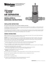
Viega ProPress ttings are manufactured with a high-quality, shiny black EPDM
(Ethylene Propylene Diene Monomer) sealing element installed at the factory.
The molded sealing lips also seal tube surfaces with slightly uneven surfaces.
Sealing elements are inserted into the tting using a H1 food grade lubricant
registered with NSF and the USDA, and is approved for use under FDA 21 CFR.
The EPDM sealing element possesses excellent resistance to aging,
ozone, sunlight, weathering, environmental inuences, and most alkaline
solutions and chemicals used in a broad range of applications.
The operating temperature of the EPDM sealing element is 0° to 250°F
(-18° to 120°C).
2.4.5.3 EPDM Sealing Element
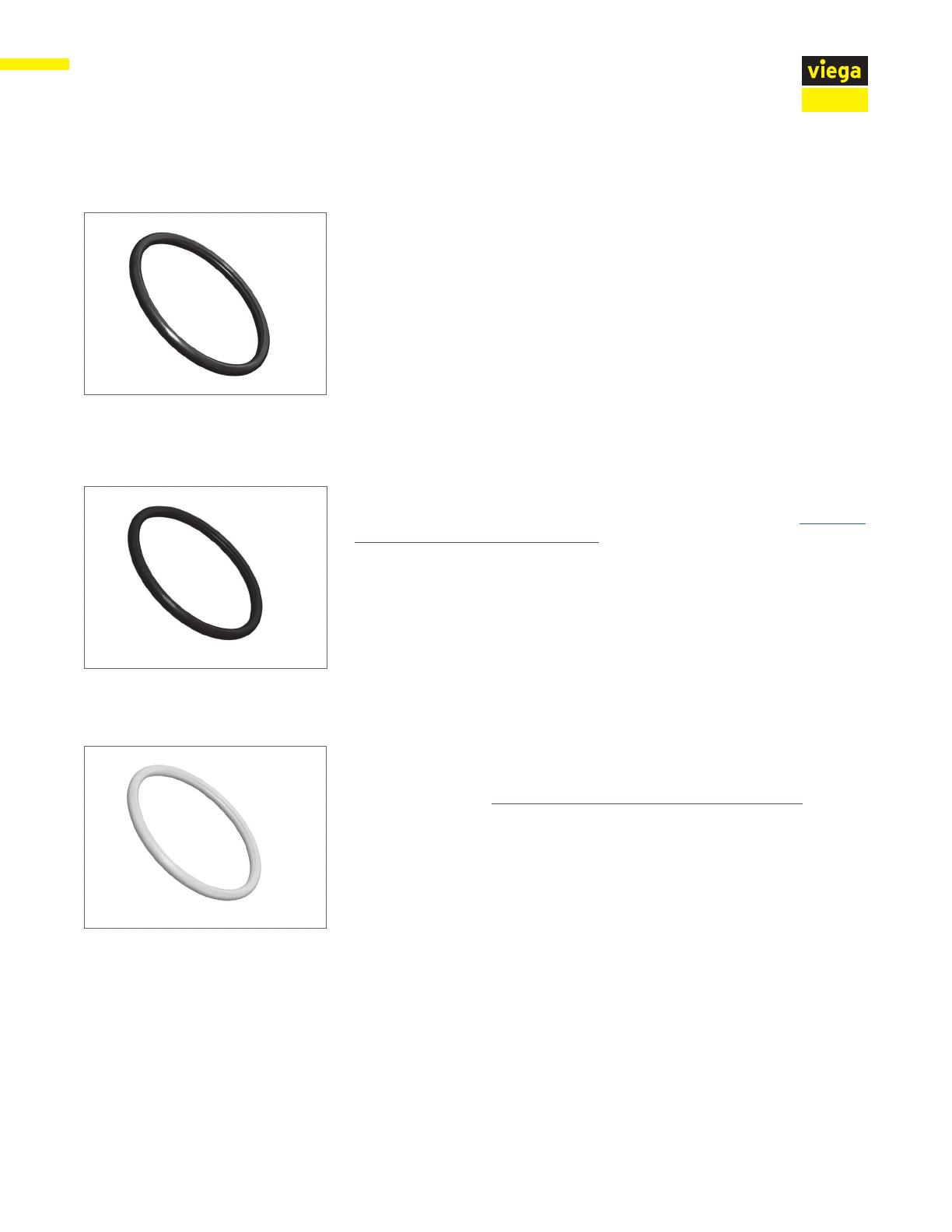
ProPress ttings may be changed from the factory-installed EPDM sealing
element to an dull black FKM (Fluoroelastomer) sealing element. See Changing
Sealing Elements Product Instructions. FKM is well known for its excellent
resistance to petroleum products and solvents as well as exceptional high-
temperature performance, which make it ideal for seals and gaskets in solar,
district heating, low-pressure steam, and compressed air system.
It possesses
excellent resistance to aging, ozone, UV, weathering, environmental
inuences, and oils and petroleum-based additives.
The operating temperature of the FKM sealing element is 14° to 284°F
(-10° to 140°C) with temperature spikes up to 356°F.
2.4.5.4 FKM Sealing Element
ProPress press ttings may be changed from the factory-installed EPDM
sealing element to a yellow HNBR (Hydrogenated Nitrile Butadiene Rubber)
sealing element. See Changing Sealing Elements Product Instructions. The
HNBR sealing element is used mainly for inert gas, liquid fuel, and lubricant oil.
It is commonly used in fuel oil heating systems.
HNBR is widely known for its physical strength and retention of its properties
after long-term exposure to heat, oil, and chemicals.
The unique properties of the HNBR sealing element have resulted in the wide
adoption of it in automotive, industrial, and assorted performance-demanding
applications (e.g., engine seals, grommets, and gaskets; fuel system seals
and hoses; transmission system bonded piston seals; chevron seals, oil eld
packers, and rotary shaft seals.)
The HNBR sealing element is not suitable for food contact applications and
cannot be installed in drinking water applications.
The operating temperature of the HNBR sealing element is -40° to 180°F
(-40°C to 82°C).
2.4.5.5 HNBR Sealing Element