Page is loading ...

GRUNDFOS INSTRUCTIONS
Oxiperm
®
Pro
OCD-162
Installation and operating instructions

English (US)
2
English (US) Installation and operating instructions
Original installation and operating instructions.
CONTENTS
Page
1. Limited warranty
3
2. Symbols used in this document
3
3. General safety instructions
3
3.1 Purpose of these operating instructions
3
3.2 Operators
3
3.3 User requirements
3
3.4 Authorized service personnel
4
3.5 Correct usage
4
3.6 Inappropriate usage
4
3.7 Safety and monitoring equipment
4
3.8 Chemicals
4
4. Product description
6
4.1 Application examples
7
4.2 Functional principle
7
4.3 Components of a standard system
8
4.4 Peripheral devices and accessories
12
4.5 Hydraulic connections
12
4.6 Power supply connections and electronic connections
14
4.7 Operation modes
14
4.8 Display and control elements
14
4.9 Access codes
16
4.10 Menu structure
16
5. Technical data
18
5.1 Identification
18
5.2 Technical data
20
5.3 Dimensions
22
5.4 Weights and capacities
24
5.5 Permissible chemicals
24
5.6 Materials
24
5.7 Dosing pumps
24
5.8 Dilution water
24
5.9 Measuring cell
24
6. Product numbers
25
6.1 Electrical data
25
6.2 Controller inputs
25
6.3 Controller outputs
25
7. Transport and packaging
26
7.1 Unpacking
26
7.2 Transport damage
26
8. Installation
26
8.1 Preparing the installation location
26
8.2 Preparing for installation
27
8.3 Connecting the power supply cable
27
9. Operation
28
9.1 Switching on the system
28
9.2 Starting production
28
9.3 Terminating production and ClO2 dosing
29
9.4 Continuing production after an interruption
29
9.5 Flushing
30
9.6 Manually venting the dosing pump
31
9.7 Modifying setup
32
9.8 Monitoring the production and dosing process
33
9.9 Setting the warning relay and alarm relay
38
9.10 Configuring the warning relay
39
9.11 Faults with error message
41
9.12 Faults without error message
46
9.13 Calibration
46
9.14 Manually starting or stopping ClO2 dosing
49
9.15 Switching off the system
49
10. Maintenance
50
10.1 Cleaning
50
11. Accessories list
50
12. Photos
51
13. Disposal
53
Warning
Prior to installation, read these installation and
operating instructions. Installation and operation
must comply with local regulations and accepted
codes of good practice.
Warning
The use of this product requires experience with
and knowledge of the product.
Persons with reduced physical, sensory or
mental capabilities must not use this product,
unless they are under supervision or have been
instructed in the use of the product by a person
responsible for their safety.
Children must not use or play with this product.

3
English (US)
1. Limited warranty
Products manufactured by GRUNDFOS PUMPS CORPORATION
(Grundfos) are warranted to the original user only to be free of
defects in material and workmanship for a period of 24 months
from date of installation, but not more than 30 months from date
of manufacture. Grundfos' liability under this warranty shall be
limited to repairing or replacing at Grundfos' option, without
charge, F.O.B. Grundfos' factory or authorized service station,
any product of Grundfos' manufacture. Grundfos will not be liable
for any costs of removal, installation, transportation, or any other
charges which may arise in connection with a warranty claim.
Products which are sold but not manufactured by Grundfos are
subject to the warranty provided by the manufacturer of said
products and not by Grundfos' warranty. Grundfos will not be
liable for damage or wear to products caused by abnormal
operating conditions, accident, abuse, misuse, unauthorized
alteration or repair, or if the product was not installed in
accordance with Grundfos' printed installation and operating
instructions.
To obtain service under this warranty, the defective product must
be returned to the distributor or dealer of Grundfos' products from
which it was purchased together with proof of purchase and
installation date, failure date, and supporting installation data.
Unless otherwise provided, the distributor or dealer will contact
Grundfos or an authorized service station for instructions.
Any defective product to be returned to Grundfos or a service
station must be sent freight prepaid; documentation supporting
the warranty claim and/or a Return Material Authorization must
be included if so instructed.
GRUNDFOS WILL NOT BE LIABLE FOR ANY INCIDENTAL OR
CONSEQUENTIAL DAMAGES, LOSSES, OR EXPENSES
ARISING FROM INSTALLATION, USE, OR ANY OTHER
CAUSES. THERE ARE NO EXPRESS OR IMPLIED
WARRANTIES, INCLUDING MERCHANTABILITY OR FITNESS
FOR A PARTICULAR PURPOSE, WHICH EXTEND BEYOND
THOSE WARRANTIES DESCRIBED OR REFERRED TO
ABOVE.
Some jurisdictions do not allow the exclusion or limitation of
incidental or consequential damages and some jurisdictions do
not allow limit actions on how long implied warranties may last.
Therefore, the above limitations or exclusions may not apply to
you. This warranty gives you specific legal rights and you may
also have other rights which vary from jurisdiction to jurisdiction.
2. Symbols used in this document
The safety instructions are identified by the following symbols:
3. General safety instructions
3.1 Purpose of these operating instructions
These operating instructions inform about operating and
monitoring the system with software version not older than
V 1.03.0. For information on installation, maintenance, servicing
and dismantling, please see the separate Service Instructions.
Information about possible residual risks can be found:
• on warning signs located at the installation site
• at the beginning of each section in this manual
• immediately before steps associated with a residual risk.
3.2 Operators
Operators are persons who are responsible for operating and
monitoring the system at the installation location. The system
may only be operated by trained and qualified personnel.
The system is electronically controlled. Operators operate the
system via a display with control elements.
Obligations of the operator:
• Be trained by qualified personnel from Grundfos in the
operation of the system.
• Observe the recognized regulations governing safety in the
workplace and accident prevention.
• Wear appropriate personal protective equipment in
accordance with national regulations for the prevention of
accidents when operating the system and handling chemicals.
• Control access to the operator code for the operating software.
3.3 User requirements
Owners of the building and/or operators of the Oxiperm Pro
disinfection system are obliged to:
• Keep this manual as a reference for operators while the
system remains in use.
• Meet the installation requirements specified by the
manufacturer. See section 8.1 Preparing the installation
location.
• Make sure that water and chemical lines and fittings are
regularly checked, serviced and maintained.
• Obtain official approval for storing chemicals, if necessary.
• Provide operator training for proper equipment use.
• Make sure that the labels supplied by the manufacturer are
attached and clearly visible in the installation location.
For illustration, see section 12. Photos.
• Provide the access code for the operating software only to
operators who have received appropriate technical training.
• Learn and follow all health and safety regulations (OSHA,
etc.).
• Provide all operators and service personnel with personal
protective equipment as needed.
Warning
If these safety instructions are not observed,
it may result in personal injury.
Caution
If these safety instructions are not observed,
it may result in malfunction or damage to the
equipment.
Note
Note
Notes or instructions that make the job easier
and ensure safe operation.

English (US)
4
3.4 Authorized service personnel
The system may only be maintained and serviced by authorized
service personnel trained by Grundfos.
3.5 Correct usage
Oxiperm Pro OCD-162 is a system for generating a chlorine
dioxide solution out of hydrochloric acid (9 %) and sodium chlorite
(7.5 %), and the continuous dosing of this solution for water
disinfection.
3.6 Inappropriate usage
Applications other than those listed in section 3.5 Correct usage
are not in accordance with the intended use and are not
permitted. The manufacturer, Grundfos, accepts no liability for
any damage resulting from incorrect use.
A chlorine dioxide solution with an uncritical concentration of
2000 ppm (2 g/l) is generated in the reactor. Hence the
Oxiperm Pro OCD-162 operates far out of the range of critical
concentrations.
Danger of explosion in case of overdosage: At a concentration of
more than 30,000 ppm (30 g/l) the chlorine dioxide solution can
explode.
Gaseous chlorine dioxide is a chemically unstable compound.
At concentrations over 300 ppm (300 g/m
3
), it decomposes into
chlorine and oxygen explosively without external impact.
3.7 Safety and monitoring equipment
The system features control alarms that monitor ClO
2
production.
An additional gas warning device is available as an accessory.
3.8 Chemicals
3.8.1 Chlorine dioxide concentration
In the reaction tank of the Oxiperm Pro OCD-162, diluted sodium
chlorite and diluted hydrochloric acid are mixed to create a
chlorine dioxide solution with a concentration of approximately
20 grams per liter of water. After further dilution and according to
the disinfection demand, the Oxiperm Pro OCD-162 doses the
diluted chlorine dioxide solution into the main line to be
disinfected. The ClO
2
concentration in drinking water must not
exceed a maximum of 0.4 milligram per liter of water according to
some drinking water ordinances; check federal, state, and local
ordinances. Under adverse conditions, the 55 g system could
potentially liberate 1.5 g ClO
2
gas.
3.8.2 Storing chemicals
• Chemicals must be stored in the appropriately marked original
plastic containers.
• Do not store chemicals near grease, flammable substances,
oils, oxidizing substances, acids or salts.
• Empty and full containers must be kept closed, especially in
areas where national regulations for the prevention of
accidents apply to storage.
Warning
Unauthorized structural modifications to the
system may result in serious damage to
equipment and personal injury.
It is prohibited to dismantle, modify, change the
structure of, bridge, remove, bypass or disable
components, including safety equipment.
Warning
Risk of explosion when using chemicals in too
high concentrations.
Only use sodium chlorite in a diluted
concentration of 7.5 % by weight in accordance
with EN 938.
Only use hydrochloric acid in a diluted
concentration of 9.0 % by weight in accordance
with EN 939.
Observe the safety data sheets from the
chemicals supplier.
Warning
Risk of explosion when mixing up chemical
containers or suction lances.
Possible consequences are personal injury and
serious damage to equipment.
Do not mix up chemical containers or suction
lances.
Observe the labels on chemical containers,
suction lances and pumps: red = HCl,
blue = NaClO
2
.
Warning
Risk of burns when skin and clothing come into
contact with sodium chlorite and hydrochloric
acid.
Immediately wash affected skin and clothing with
water.
Warning
Risk of irritation to eyes, respiratory system and
skin, if chlorine dioxide is inhaled.
When changing the chemical containers, wear
personal protective equipment per OSHA
guidelines and as directed by local/state/national
regulations.
Warning
The temperature of the chlorine dioxide solution
stored in an external batch tank may not exceed
104 °F (40 °C).
Risk of outgassing at more than 104 °F (40 °C).
Note
Note
Installing a gas warning device is recommended.

5
English (US)
3.8.3 Procedure in case of an emergency
The general safety regulations and regulations for the procedure
in case of an emergency apply. See NIOSH, OSHA, EN 12671
guidelines.
Actions in case of an emergency:
• Ventilate the installation location immediately.
• Wear personal protective equipment (safety goggles, gloves,
respirator and/or self-contained breathing apparatus,
protective apron).
• Implement initial help measures
– In case of contact with the eyes, rinse immediately with
plenty of water for at least 15 minutes. Consult a physician.
– In case of contact with the skin, wash immediately with
plenty of water. Remove all contaminated clothing.
– In case of gas inhalation, move to fresh air. Avoid taking
deep breaths.
– Consult a physician (look out for a racing pulse, as
vasodilating treatment may be required).
• Spills
– Evacuate the danger area and consult an expert!
– In case of contact with clothing, remove the clothing
immediately and wash with plenty of water.
– Chemical spills in buildings must be washed away with
water.
– Chlorine dioxide spills can be doused with sodium
thiosulphate, and washed away with water.
• Escaped gas
– Escaped gas can be rinsed away with water from a
sprinkling system.
• Firefighting
– Aqueous solutions of chlorine dioxide are not directly
flammable. Extinguish the surrounding fire with water,
preferably using a fire sprinkler system to dilute the ambient
gas. Inform the fire department of the installed production
capacity and any harmful starting substances that are being
stored (precursor chemicals) so that precautions can be
taken to minimize risk.

English (US)
6
4. Product description
Oxiperm Pro OCD-162 disinfection systems produce and dose
chlorine dioxide for the disinfection of drinking water, process
water, cooling water and wastewater.
Oxiperm Pro consists of a plastic system frame, on which the
internal components are mounted. They are prepared for wall- or
floor-mounting, and covered by a plastic cover.
The chemicals are supplied from two separate chemical
containers which should be isolated from one another with
separate secondary containment. A suction lance is inserted in
each container and is permanently connected to the
corresponding precursor dosing pump. The suction lance cables
send low-level and empty signals to the controller.
The Oxiperm Pro OCD-162 is connected to two water lines:
• The potable water line for supplying dilution water and flushing
water.
• The main water line to be disinfected, into which the final
chlorine dioxide solution is dosed.
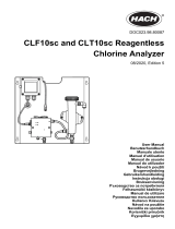
Fig. 1 Oxiperm Pro OCD-162 without cover and peripheral devices
TM04 8541 1312
TM04 7657 1413

7
English (US)
4.1 Application examples
Oxiperm Pro OCD-162 disinfection systems can be used for
different types of applications:
4.1.1 Disinfection of potable water lines
• The flow rate in drinking water lines can fluctuate greatly
(peak times when water is used for bathing and cooking).
• The type and level of contamination in the water
(disturbance variables) are not known or greatly vary.
• Examples: potable water lines in:
– hotels, multi-floor buildings
– schools, hospitals, convalescent homes
– showers, health spas
– food and beverage plants
– waterworks.
4.1.2 Disinfection of industrial systems
• The water quantity in industrial systems is relatively constant.
• The type and level of contamination in the water
(disturbance variables) are generally measured.
• Examples:
– bottle washing, breweries
– industrial process water or wastewater systems
– cooling water systems.
4.1.3 Shock disinfection (with external batch tank)
• Applications requiring large quantities of disinfectant in a short
time
• Example: pools and spas.
4.2 Functional principle
4.2.1 Production of chlorine dioxide
Chlorine dioxide is prepared in the reaction tank as follows:
Water, hydrochloric acid and sodium chlorite are added until a
specific level is reached. During the reaction time, a diluted
chlorine dioxide solution is produced. The reaction tank is filled
with water. With a concentration of approximately 2000 ppm, the
final solution flows through a pipe (overflow) located in the middle
of the reaction tank into the batch tank below.
From the batch tank, the dosing pump feeds the final chlorine
dioxide solution to the injection unit, where it is injected into the
main water line to be disinfected.
See section 4.7 Operation modes for operating mode information.
4.2.2 Flow-rate-proportional dosing
1. The controller is set to "proportional controller".
2. A contact water meter or flow meter measures the water flow
rate in the main water line, and continuously sends measured
values to the controller.
3. The proportional controller calculates the required chlorine
dioxide feed rate in proportion to the water flow rate in the
main line.
4. The proportional controller sends the corresponding output
signals to the dosing pump.
5. The dosing pump feeds the required quantity of chlorine
dioxide solution from the batch tank into the main water line.
6. An optional measuring cell monitors the chlorine dioxide
concentration in the main line.
4.2.3 Setpoint-controlled dosing
1. The controller is set to "setpoint controller". A setpoint for the
desired chlorine dioxide concentration in the main line is
specified.
2. A measuring cell monitors the chlorine dioxide concentration
in the main line, and sends actual values to the controller.
3. The setpoint controller compares the incoming actual values
with the setpoint. Based on the deviation, it calculates the
quantity of chlorine dioxide solution (actuating variable)
required to achieve the desired concentration.
4. The setpoint controller sends output signals to the dosing
pump.
5. The dosing pump feeds the corresponding quantity of chlorine
dioxide solution from the batch tank into the main water line.
A combined controller is also available for applications with
setpoint controller and flow meter, see separate Service
Instructions.

English (US)
8
4.3 Components of a standard system
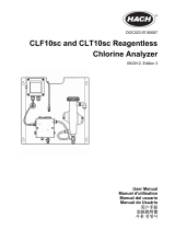
Fig. 2 Components of a standard system (Oxiperm Pro OCD-162-5, -10)
TM05 7222 0713
Blue
Red

9
English (US)
4.3.1 External components
See the photos in section 12. Photos.
4.3.2 Internal components
Pos. Component
1a Water line for dilution water and flushing water
1b Dilution water extraction device with isolating valve
3
Container for sodium chlorite (NaClO
2
, diluted
concentration of 7.5 % by weight) with suction lance and
secondary containment
4
Container for hydrochloric acid (HCl, diluted
concentration of 9 % by weight) with suction lance and
secondary containment
11 Main water line to be disinfected
12 Flow meter (or contact water meter)
14 Dosing line
15
Injection unit for dosing chlorine dioxide (ClO
2
) into the
main water line
16 Sample water line to measuring cell (AQC)
17 Sample-water extraction device
18
Measuring cell (Grundfos AQC-D11) for checking the
chlorine dioxide concentration in the main water line
19 Power supply connection
Pos. Component
2 Solenoid valve for dilution water and flushing water
5 Dosing pump for sodium chlorite (NaClO
2
)
6 Dosing pump for hydrochloric acid (HCl)
7 Reaction tank with float switch
8
Batch tank with float switch and drain cock for chlorine
dioxide (ClO
2
)
9 Volume compensation bag for chlorine dioxide gas
10 Activated carbon filter for chlorine dioxide gas
13
Dosing pump with multi-function valve for chlorine
dioxide
20 Electronic controller for ClO
2
measurement and control
21 Analyzer and controller with plain text display

English (US)
10
Fig. 3 OCD-162-5, -10 system with measuring cell and without extension module
Fig. 4 Complete system with measuring cell (e.g. OCD-162-30, -60)
TM05 7221 0713TM05 7992 1713
Red
Blue

11
English (US)
Pos. Component
1a Water line for dilution water and flushing water
1b Dilution water extraction device with isolating valve
3 Container for sodium chlorite (NaClO
2
, diluted concentration of 7.5 % by weight) with suction lance and secondary containment
4 Container for hydrochloric acid (HCl, diluted concentration of 9 % by weight) with suction lance and secondary containment
11 Main water line to be disinfected
12 Flow meter (or contact water meter)
14 Dosing line
15 Injection unit for dosing chlorine dioxide (ClO
2
) into the main water line
16 Sample water line
17 Sample-water extraction device
18 Grundfos AQC-D11 measuring cell
19 Power supply connection/main switch
23 Connection cable for measuring cell
24 Sample-water drain
25 Connection cable for cleaning motor
26 Dilution water line

English (US)
12
4.4 Peripheral devices and accessories
4.4.1 Accessories for the dilution water line
• Isolating valve.
• Dilution water extraction device (if necessary with double
nipple and connection piece for hose).
• Hose with connection to solenoid valve.
4.4.2 Accessories for the main water line
• Contact water meter or flow meter (in case of a new water line:
Water flow meter providing signals, or ultrasonic flow meter).
• Tapping sleeve for the injection unit.
• Protective pipe for the ClO
2
line, installed from the dosing
pump to the injection unit.
• Grundfos DIT photometer: measures the chlorine dioxide
concentration after dosing and useful for system calibration.
• Sample-water filter (in case of insufficient water quality).
4.4.3 Measuring cell
• Grundfos AQC-D11 measuring cell.
• Tapping sleeve for sample-water extraction at the main line.
• Hose from the sample-water extraction device to the
measuring cell.
• Hose from the measuring cell to the sample-water drain.
4.5 Hydraulic connections
4.5.1 Oxiperm Pro OCD-162-5, -10
Fig. 5 Hydraulic connections OCD-162-05, -10
TM04 8542 1312
Pos. Description
5, 6
Tubing for both suction lances on the suction side of
the NaClO
2
and HCl dosing pumps
8
Tube at the drain cock of the batch tank (only installed
for flushing and venting)
14
Dosing line from the chlorine dioxide pump to the
injection unit at the main line or to the external batch
tank
26 Dilution water line at the solenoid valve
Note
Note
See section 5.2 Technical data on page 20 for
connection sizes.

13
English (US)
4.5.2 Oxiperm Pro OCD-162-30, -60
Fig. 6 Hydraulic connections OCD-162-30, -60
TM05 7233 0813
OCD-162-30
OCD-162-60
Pos. Description
5, 6
Tubing for both suction lances on the suction side of
the NaClO
2
and HCl dosing pumps
8
Tube at the drain cock of the batch tank (only installed
for flushing and venting)
14
Dosing line from the ClO
2
pump to the injection unit at
the main line or to the external batch tank
26 Dilution water line at the solenoid valve
Note
Note
See section 5.2 Technical data on page 20 for
connection sizes.

English (US)
14
4.5.3 System connections
• Dilution water line at the solenoid valve (26)
• Tubing for suction lances (5, 6)
•ClO
2
line from the dosing pump to the injection unit at the main
line or to the external batch tank (14)
• Tube at the drain cock of the batch tank (8).
4.5.4 Measuring cell connections
The measuring cell is hydraulically connected to the main line.
After dosing, the chlorine dioxide concentration, temperature and
pH/ORP value of the sample water are measured in the
measuring cell. The measuring cell has connections for the
following:
• 3/8" ID x 1/2" OD tube from the sample-water extraction
device to the measuring cell
• 3/8" ID x 1/2" OD tube from the measuring cell to the
sample-water drain.
For more detailed information, see the installation and operating
instructions for the Grundfos AQC-D11 measuring cell.
4.6 Power supply connections and electronic
connections
The Oxiperm Pro OCD-162 is equipped with an electronic
controller. The controller has connections for the following:
• power supply cable to the main switch
• cable from the flow meter or contact water meter
• cable from external batch tank to level control, if applicable
• cables for measuring cell AQC-D11 or AQC-D6, if applicable:
– measuring electrode
– sample-water flow sensor
– Pt100 temperature sensor
– pH or ORP electrode
– cleaning motor.
For additional connections, see the separate Service Instructions.
4.7 Operation modes
During startup, the Oxiperm Pro OCD-162 system is programmed
to meet the application control requirements. Once powered on,
automatic ClO
2
production is set via the plain text menu controls.
Two operation modes are available:
• "Internal batch tank" mode: Chlorine dioxide solution is
generated in the internal batch tank, and dosed into the line
system, until the batch tank is empty. There are two ways of
refilling the batch tank:
– First method "1-20": You determine how many times the
batch tank is refilled by choosing a number in the range of 1
to 20.
– Second method "0 = continuous": The batch tank is refilled
continuously.
• "External batch tank" mode: Chlorine dioxide solution is
generated in the internal reaction tank, and fed into an
external batch tank with level controls for storage.
After emptying the external batch tank, ClO
2
production is
restarted in a continuous process.
Dosing is controlled automatically by the controller. In manual
operation, the controller can be switched off.
4.8 Display and control elements
Fig. 7 Display and control elements
4.8.1 Displays
After switching on the system, the following display appears:
Fig. 8 Starting the system
Press [OK] to access the "main menu":
TM05 8199 2013
Button or LED Function
Button [Esc] Cancels command, exits menu
Button [Up]
Selects the previous menu item, or sets a
higher numerical value
Button [Down]
Selects the next menu item, or sets a
lower numerical value
Button [OK] Confirms the menu selection
Button [Cal] Calibration
Button [Man] Manual operation
LED "Alarm" Alarm (red)
LED "Caution" Warning (yellow)
LED "Cal" Calibration (yellow)
LED "Man" Manual operation (yellow)
TM03 6921 4506
main menu
settings
ctrl. parameters
operation
service
commissioning
maintenance date
54321

15
English (US)
During operation, press [Esc] to access the display level:
Fig. 9 "prod. running" display level
The header indicates the status. The positions are explained in
the table below.
Legend
TM03 6922 4506
.........
24
,
5
°C
pH
7
,
35
5
4
3
2
1
0
,
23 mg
/
l
1
2
6
7
4/3
5
8
Pos. Message Description
1
Headers
"prod. running" Chlorine dioxide production is active.
"prod. terminated" Chlorine dioxide production has been stopped.
"[N/A]" Chlorine dioxide production has been terminated by a menu command or alarm.
"flushing" Flushing is started automatically or manually.
2
Relays
1
Relay for solenoid valve:
White number on a black background: relay active.
Black number on a white background: relay not active.
2 Relay for hydrochloric acid pump: display as for 1.
3 Relay for sodium chlorite pump: display as for 1.
4 Alarm relay: display as for 1.
5 Warning relay: display as for 1.
3
Symbol
Symbol for the relay of the interpulse controller.
Symbol for relay stop of the interpulse controller.
4
Symbol
Symbol for continuous controller: Box with plotted line.
The height of the line is proportional to the actuating variable (chlorine dioxide dosing volume).
Line not visible: actuating variable = 0 %. Line fills the entire box: actuating variable = 100 %.
Symbol for stop of the continuous controller: White box with a diagonal line through it.
5
Symbol
Symbol for external disturbance value input (water flow as impulse/current signal).
Box with plotted triangle.
The black fill is proportional to the flow (the greater the fill, the greater the flow, 0-100 %).
(only visible, if proportional or combined controller is configured).
6
Value
e.g. 24.5 °C Water temperature, display value is only available with connected measuring cell.
7
Value
e.g. 0.23 mg/l Chlorine dioxide concentration, display value is only available with connected measuring cell.
8
Value
e.g. 7.35 pH value in the sample water, display value is only available with connected measuring cell.
6
6

English (US)
16
4.9 Access codes
When the system is ready for operation, the "main menu" cannot
be accessed without a code. Two different access or security
levels are assigned for all submenus.
Each code automatically enables the levels below it.
4.9.1 Operator code
By default, all operator menus can initially be accessed without a
code. When the menu selection has been confirmed with [OK], a
code request is not displayed.
Once the operator has entered his operator code ("main menu >
commissioning > [N/A]"), the code request appears before any
operator submenu can be accessed. The modified operator code
must only allow access for operators with appropriate technical
training and experience. Access is enabled for 60 minutes after
entry of the code.
4.9.2 Service code
This code is reserved for trained Grundfos service engineers.
Access is enabled for 30 minutes after entry. The service code is
necessary for initial startup.
4.10 Menu structure
The submenus vary in submenus for operators (with operator
code) and service engineers (with service code). All software
menus can be selected from the "main menu" using the [Up] and
[Down] buttons, and accessed using [OK]. Press [Esc] to return to
the menu level above.
4.10.1 Operator menus (part 1)
Menu Submenu 1 Submenu 2 Submenu 3 Submenu 4 Submenu 5
main menu
settings
start
start chem.consumption
[N/A]
terminate
terminate monitoring
[N/A]
batch tank
int. batch tank
0 = continuous
1-20 (adjustable)
ext. batch tank on/off
service
settings
status Display: int. pump only?
list of events
production
batches
l/min HCl/NaClO2 reset
age of ClO2 (mm:ss)
maintenance date
flushing
start
terminate
[N/A]
1
ClO2
measured value
cal. logbook
temperature °C or °F (measured value)
pH or ORP
5
measured value
cal. logbook
ctrl. parameters The current controller parameter is in section 9.8.2 Current control parameters.
water meter
2
E.g. 5 impulses/sec. = 50 %
or 10 mA = 50 %
3
[N/A]
software version

17
English (US)
1
The "Measurement" submenu only appears, if it is enabled in the "Setup" menu.
2
The "Water flow meter" submenu only appears, if a "Water flow meter" is enabled in the "Setup" menu.
3
Depending on the type of water flow meter enabled.
4
The alarm settings only appear if "Measurement" is enabled in the setup menu.
5
Depending on the setting in the "Setup" menu.
Operator menus (part 2)
6
Press the [Cal] button to access the calibration menu.
7
Press the [Man] button for manual operation.
Operators can view the current input value of the water flow
meter as well as the impulses/second, or the value in mA and the
calculation in percent, see section 9.8.3 Current input value for
water flow meter.
The value is also displayed, if the defined input values are
exceeded or not reached (a water flow meter malfunction is
visible here).
main menu
commissionin
g
language
ClO2 value
ClO2 dosing
(all listed)
date/time
date
time
super-user
Begin, HCl empty, system
waiting, NaClO2 empty,
system waiting
(± x hours), off
operator code
change
delete
display display contrast
operation
4
ClO2 alarm
internal
external
lower limit: 0.15 mg/l [N/A] or [N/A]
upper limit: 0.70 mg/l [N/A] or [N/A]
hysteresis: 0.01
alarm delay: 0 sec.
dos. time monit.
off
on max. dosing time
Menu Submenu 1 Submenu 2 Submenu 3 Submenu 4 Submenu 5
Menu Submenu 1 Submenu 2 Submenu 3 Submenu 4 Submenu 5
calibration
6
[N/A]
cal. meas. value
cal. result h/m3 µA, mg/l
cal. cycle on/off
pH
cal. meas. value
GRUNDFOS,
DIN/NIST, others
cal. result
slope µA, mg/l
asym. mV
cal. cycle on/off
ORP
cal. meas. value
cal. result [N/A] mV
cal. cycle on/off
manually dosing
7
ctrl. parameters on/off

English (US)
18
5. Technical data
5.1 Identification
5.1.1 Type key
Example: Type key Oxiperm Pro OCD-162-30-P/H3
Oxiperm Pro OCD-162 -30 -P /H 3
Max. Capacity
55 g/h
10 10 g/h
30 30 g/h
60 55 g/h
Operation mode
D integrated mechanical dosing pump, DMX
P integrated Digital Dosing pump DDI
S integrated SMART Digital Dosing pump DDA
N without integrated ClO
2
dosing pump
Supply voltage
G 230-240 V / 50-60 Hz
H 110-120 V / 50-60 Hz
Suction line
for 7.9 gal (30 liter) chemical tank, with 4.3 ft (1.3 m) of tubing
1 for 15.6 gal (60 liter) chemical tank, with 9.8 ft (3.0 m) of tubing
2 for 52.8 gal / 264.2 gal (200 liter / 1000 liter) chemical tank, with 19.7 ft (6.0 m) of tubing
3 for 55 gal drum, with 9.8 ft (3.0 m) of tubing

19
English (US)
5.1.2 Nameplate
Fig. 10 Nameplate (for OCD-162-5-S/H3)
TM05 7133 0613
Pos. Description
1 Type designation
2 Product name
3 Model
4 Serial number
5 Chlorine dioxide production capacity
6 Product number
7 Country of origin
8 Year and week of production
9 Marks of approval, NSF 61 PWT, ETL, CE mark, etc.
10 Voltage [V]
11 Frequency [Hz]
12 Power consumption
13 Safety instruction: Please read this manual
OCD-162 5S/H3
162-005-10000
5/N: 07/64064
5g/h, 120V, 50/60Hz, 850Watt
95735155P1107380764064
1
3
4
78 9
6
2
5
10, 11, 12
13

English (US)
20
5.2 Technical data
Chlorine dioxide generator
OCD model
162-5 162-10 162-30 162-60
ClO
2
production [lbs/day (grams/hr)] 0.26 (5) 0.53 (10) 1.59 (30) 2.9 (55)
ClO
2
concentration [ppm] 2000
Max continuous ClO
2
dosing feed
rate* (i.e. max. ClO
2
pump output
at 20 mA)
[gal/hr (l/hr)] 0.66 (2.5) 1.32 (5) 3.96 (15) 7.26 (27.5)
Consumption data [gal/hr (l/hr)]
NaClO
2
0.039 (0.15) 0.079 (0.3) 0.235 (0.89) 0.4 (1.5)
HCl 0.042 (0.16) 0.087 (0.33) 0.256 (0.97) 0.44 (1.67)
H
2
O 0.69 (2.6) 1.35 (5.1) 4.23 (16) 8.5 (32)
Precursor concentration by
weight
HCl 9 %
NaClO
2
7.5 %
Precursor safety equipment Capacity monitored via level control
Temperature range [°F (°C)]
Product 41 to 104 °F (5 to 40 °C)
Ambient 40 to 95 °F (5 to 35 °C)
H
2
O 50 to 85 °F (10 to 30 °C)
HCl &
NaClO
2
50 to 95 °F (10 to 35 °C)
Storage temperature of chemicals Check with chemical supplier
Dilution water pressure [psi (bar)] 44 to 87 psi (3 to 6 bar)
Permissible operation height
above sea level
6,561 ft (2000 m)
Admissible relative air humidity max. 80 %, not condensing
Max. back pressure of ClO
2
pump 145 psi (10 bar)
Total volume - reaction tank [gal (liters)] 0.26 (1.0) 0.48 (1.8) 1.6 (6.1) 3.5 (13.4)
Total volume - reservoir tank
(up to max level alarm)
[gal (liters)] 0.26 (1.0) 0.48 (1.8) 1.85 (7.0) 3.67 (13.9)
Filling volume - reaction tank [gal (liters)] 0.23 (0.87) 0.44 (1.67) 1.46 (5.52) 3.16 (11.96)
Filling volume - reservoir tank
(up to max level alarm)
[gal (liters)] 0.23 (0.87) 0.44 (1.67) 1.72 (6.5) 3.43 (13.0)
Materials of construction
System rack Polypropylene
Fastening sleeves Stainless steel
Solenoid valve PVC
Reaction/reservoir tank PVC
Internal hoses PTFE
Gaskets FPM
Connections
ClO
2
dosing line 1/8" ID x 1/4" OD tube 1/4" ID x 3/8" OD tube
Dilution water 1/4" ID x 3/8" OD tube
NPT adaptor 1/2" NPT connector - see 11. Accessories list on page 50.
Full text menu control
Commissioning Yes
Operation parameters Yes
Flush/rinsing Yes
Maintenance Yes
Voltage frequency 115 V, 50-60 Hz
/