Page is loading ...

Oxiperm
®
OCD-164 (30-2000 g/h)
Installation and operating instructions
GRUNDFOS INSTRUCTIONS
Other languages
http://net.grundfos.com/qr/i/96709679

English (GB)
2
English (GB) Installation and operating instructions
Original installation and operating instructions
Contents
Page
1. General safety instructions
1.1 Introduction
The OCD-164 disinfection system is a state-of-the-art solution,
which complies with recognised safety regulations.
Conformity with applicable standards, directives and laws has
been verified. Nevertheless, certain risks which cannot be
prevented by the manufacturer are associated with the use of the
system.
1.2 Purpose of this manual
• Inform users of optimum use of the system.
• Warn users of possible residual risks when using the system
correctly, and identify measures that should be taken to avoid
damage.
• Caution users against obvious misuse or inappropriate use of
the system, and inform them of the necessary care that must
be taken when operating the system.
1.3 Symbols used in this document
Information about possible residual risks can be found:
• on warning signs located at the installation site, and
• immediately before steps associated with a residual risk.
1. General safety instructions
2
1.1 Introduction
2
1.2 Purpose of this manual
2
1.3 Symbols used in this document
2
1.4 Users
3
1.5 Obligations of the operator
3
1.6 Maintenance and service personnel
3
1.7 Correct usage
3
1.8 Inappropriate usage
3
1.9 Safety and monitoring equipment
3
1.10 Chemicals
3
2. Technical data
5
2.1 General data
5
2.2 Electrical data
7
2.3 Delivery state
7
3. Fundamentals
8
3.1 Chlorine dioxide for water treatment
8
3.2 Functional sequence
8
4. Design and function
9
4.1 Design of the system
9
4.2 Components
10
4.3 Mode of operation of the system
10
5. Installation
11
5.1 Transport and storage
11
5.2 Unpacking
11
5.3 Installation location
11
5.4 Installation scheme
12
5.5 Wall mounting
14
5.6 Hydraulic connection
14
5.7 Electrical connection
15
5.8 Interfaces RS-232, -422 and -485
17
6. Operation of control electronics
18
6.1 Program structure
18
6.2 Control and display elements
19
6.3 Automatic mode
19
6.4 Manual operation
19
6.5 Logbook
19
6.6 System choice
20
6.7 Units
20
6.8 Setup
20
6.9 Local/remote
23
7. Commissioning
24
7.1 Directives
24
7.2 System choice
24
7.3 Selection of operation mode
24
7.4 Venting of the bypass line
27
7.5 Calibrating the dosing pumps
29
7.6 Adjusting the dosing controllers
30
8. Operation of the system
31
8.1 Automatic operation
31
8.2 Manual operation
33
8.3 Faults
34
8.4 Error messages of the controller
35
8.5 Fuses and LEDs of the controller
36
8.6 Possible faults when changing the tank
36
9. Maintenance
37
9.1 Maintenance of the dosing pumps
37
9.2 Maintenance of the suction lines
37
9.3 Maintenance of reactor
38
9.4 Maintenance of injector
39
10. Spare parts kits and spare parts
40
10.1 DMI dosing pumps with double-head system
40
10.2 DMI dosing pumps with single-head system
41
10.3 Dosing pumps DMX 221
41
10.4 Bypass, post mixer, and dosing controller
41
10.5 Enclosure exhaust device
42
10.6 Bypass with solenoid valve and flow limiter (standard
version: solenoid valve)
43
10.7 Bypass, circulating pump 230 V - 50 Hz, 120 V - 60 Hz
44
10.8 Bypass (version solenoid valve/ball valve, batch mode)
45
10.9 Bypass for external booster pump
47
11. Accessories
48
11.1 External booster pump
48
11.2 Load unit for booster pump
50
11.3 Hose connections/hose
50
11.4 Gas sensor and gas warning device
50
12. Current setting data
51
13. Quick Guide
52
14. Disposal
52
Warning
If these safety instructions are not observed, it may
result in personal injury.
Caution
If these safety instructions are not observed, it may
result in malfunction or damage to the equipment.
Note
Notes or instructions that make the job easier and
ensure safe operation.

English (GB)
3
1.4 Users
Users are persons who are responsible for operating and
monitoring the disinfection system at the installation location.
The system must only be operated by trained and qualified
personnel. Personnel must have appropriate technical knowledge
and be familiar with the basic principles of measurement and
control technology.
1.4.1 Obligations of the users
• Read this manual before operating the disinfection system.
• Be trained by qualified personnel from Grundfos Water
Treatment in the operation of the system.
• Observe the recognised regulations governing safety in the
workplace and accident prevention.
• Wear appropriate protective clothing in accordance with
national regulations for the prevention of accidents when
operating the system and handling chemicals.
• Keep secret the user code for the operating software.
1.4.2 User workstation
The disinfection system is electronically controlled. Users and
service personnel operate the system via a display with control and
display elements. See section 6.2 Control and display elements.
1.5 Obligations of the operator
The owner of the building or the operator of the disinfection
system is responsible for the following:
• Keep this manual clearly accessible in the immediate vicinity
of the system.
• Meet the installation requirements specified by the
manufacturer (required water connections and fittings,
environmental conditions, electrical connection, protective
tube for dosing line (if necessary), audible or optical warning
device for alarm messages (if necessary)).
• Ensure that water lines and fixings are regularly checked,
serviced and maintained.
• Obtain official approval for storing chemicals, if necessary.
• Instruct users in the operation of the system.
• Provide the user code for the operating software only to users
who have received appropriate technical training.
• Ensure that the regulations for the prevention of accidents are
observed in the installation location.
• Provide all users and service personnel with protective
clothing (face mask, gloves, protective apron).
1.6 Maintenance and service personnel
The system may only be maintained and serviced by authorised
service personnel from Grundfos Water Treatment.
1.7 Correct usage
The disinfection system is used to mix a diluted chlorine dioxide
solution from 7.5 % sodium chlorite and 9 % hydrochloric acid.
In accordance with the conditions described in this manual, it is
used to dose the chlorine dioxide solution produced continuously
or non-continuously into the (drinking) water line of a building or
to feed it into a swimming pool, process water, wastewater or
other industrial system for water disinfection.
1.8 Inappropriate usage
Applications other than those listed in section 1.7 Correct usage
are not in accordance with the intended use and are not
permitted. The manufacturer, Grundfos Water Treatment,
accepts no liability for any damage resulting from incorrect use.
The system comprises state-of-the-art components and has
undergone safety-related testing.
1.9 Safety and monitoring equipment
The disinfection system is fitted with the following safety and
monitoring equipment:
• two collecting trays for the two chemical containers
(accessories),
• alarm functions in the control system.
1.10 Chemicals
1.10.1 Chlorine dioxide concentration
In the reaction tank of the disinfection system, diluted sodium
chlorite and diluted hydrochloric acid are mixed to create a
chlorine dioxide concentration of approximately 20 g per litre of
water. The chlorine dioxide solution is diluted again, and dosed
into the main line to be disinfected, according to the
requirements. According to the German drinking water ordinance
(TrinkwV 2001), the chlorine dioxide concentration in drinking
water must not exceed a maximum of 0.4 mg per litre of water.
The following safety instructions must be observed:
Warning
Unauthorised structural modifications to the system
may result in serious damage to the equipment and
personal injury.
It is forbidden to dismantle, modify, change the
structure of, bridge, remove, bypass or disable
components, including safety equipment.
Warning
Risk of explosion when using chemicals in too high a
concentration.
Only use sodium chlorite in a diluted concentration of
7.5 % by weight in accordance with DIN EN 938.
Only use hydrochloric acid in a diluted concentration
of 9.0 % by weight in accordance with DIN EN 939.
The safety data sheets from the supplier must be
observed.
Warning
Risk of explosion and serious damage to equipment
and personal injury as a result of operating faults due
to confusing the chemical containers or suction lines.
Do not confuse the containers.
Observe the red and blue markings on chemical
pumps, suction lines and chemical containers: Red =
HCl, blue = NaClO
2
.
Warning
Risk of burns when skin and clothing come into
contact with sodium chlorite and hydrochloric acid.
Affected skin and clothing must be washed
immediately in water.
Warning
Risk of irritation to eyes, respiratory system and skin,
if chlorine dioxide is inhaled.
When changing the chemical containers,
wear protective clothing in accordance with
regulations for the prevention of accidents.

English (GB)
4
1.10.2 Storing chemicals
• Chemicals must be stored in the appropriately marked original
plastic containers.
• Do not store chemicals near grease, flammable substances,
oils, oxidising substances, acids or salts.
• Empty and full containers must be kept closed, and stored
exclusively in areas where national regulations for the
prevention of accidents apply to storage.
1.10.3 Procedure in case of an emergency
The general safety regulations and regulations for the procedure
in case of an emergency as specified in EN 12671 (D) apply.
Actions in case of an emergency:
• Ventilate the installation location immediately.
• Wear protective clothing (safety goggles, gloves, respirator
and/or self-contained breathing apparatus, protective apron).
• Implement initial help measures:
– In case of contact with the eyes, rinse immediately with
plenty of water for at least 15 minutes. Consult a doctor.
– In case of contact with the skin, wash immediately with
plenty of water. Remove all contaminated clothing.
– In case gas is inhaled, move the casualty to a source of
fresh air. Avoid taking deep breaths. Consult a doctor
(look out for a racing pulse, as vasodilating treatment may
be required).
• Spillages:
– In case of contact with clothing, remove the clothing
immediately and wash with plenty of water.
Chemical spillages in buildings must be washed away with
water.
• Firefighting:
– Aqueous solutions of chlorine dioxide are not directly
flammable. Extinguish the surrounding fire with water,
preferably using a fire sprinkler system to dilute the ambient
gas. Inform the fire brigade of the installed production
capacity and any harmful starting substances that are being
stored (precursor substances) so that precautions can be
taken regarding possible risks.
For emergency phone numbers, please see the acceptance
report.

English (GB)
5
2. Technical data
2.1 General data
2.1.1 Performance and consumption data
General concentration range for all systems: 0.5 - 3.3 g/l
1) With max. preparation capacity, shortened reaction time
2) With admission pressure 2 bar higher compared with the pressure at the injection unit
3) Depends on flow losses of solution line up to injection unit
4) Concentration of ClO
2
solution approx. 3.3 g/l. Inlet pressure for bypass water: 3-8 bar
5) Concentration of ClO
2
solution approx. 2 g/l. Inlet pressure for bypass water: 3-8 bar
2.1.2 Temperatures and concentrations 2.1.3 Materials
2.1.4 Connections and weights
System
OCD-164
ClO
2
preparation capacity
Max. system
pressure
Consumption of
components
Dilution water requirement for bypass system
at 6 bar
counterpressure
50 Hz 60 Hz
1)
HCl NaClO
2
Solenoid valve
2)
(standard)
Bypass pump
3)
internal/external
In batch mode
Min.
4)
Max.
5)
g/h l/h bar bar l/h l/h l/h l/h l/h l/h
-30 30 421 10 10 0.7 0.7 420 420 7.7 14
-120 120 426 9 6 2.9 2.9 420 420 31 55
-220 220 430 7 7 5.2 5.2 420 420 56 100
-350 350 437 9 9 8.3 8.3 420 420 89 160
-700 700 933 9 9 16.5 16.5 900 900 179 320
-1000 1000 948 9 9 24 24 900 900 258 450
-1500 1500 970 9 9 35 35 900 900 383 680
-2000 2000 996 9 6 48 48 900 900 517 900
Permissible concentration of NaClO
2
solution 7.5 % by weight
Permissible concentration of the HCl solution 9.0 % by weight
Permissible ambient temperature 5 °C to 40 °C
Permissible process water temperature
(bypass water)
2 °C to 40 °C
Permissible component temperature
(chemicals)
5 °C to 40 °C
Storage temperature of system -5 °C to 50 °C
Storage temperature of chemicals 5 °C to 40 °C
Permissible relative humidity
max. 80 %,
non-condensing
Components Materials
Supporting frame PP
Screws, washers and nuts 1.4301
Reactor
Grey PVC, 1.4571 painted
RAL 6017
Post-mixer Grey PVC
Piping Grey PVC
Gaskets FPM/PTFE
164-OCD
Connection for bypass
(water inlet)
Connection for ClO
2
solution line
Enclosure exhaust device
optional
Weight of system
Motive water
pressure
Motive water
requirements
Connection,
exhaust
device
DN DN bar l/h DN kg
-30
20 20 5
800
20
33
-120 800 34
-220 800 34
-350 1300 57
-700 1300 62
-1000 1300 66
-1500 1300 76
-2000 1300 82
Caution
The solution line must be provided with a pressure
relief valve set to 10 bar.
This is a safety measure for the case that a pressure
of more than 10 bar occurs in the dilution water line
while the chlorine solution line at the outlet side of
the system is shut.

English (GB)
6
2.1.5 Dimensions
Fig. 1 Dimensioning of the system with drillholes
TM04 8193 4510
$
$
%
*
/
+
.
)
(
0
&
&&
&
OCD-164 A A1 B C E F G H K L M C1 C2
-30 700 740 650 40 800 760 230 148 148 410 9 DN 20 DN 20
-120 700 740 650 40 800 760 230 148 148 410 9 DN 20 DN 20
-220 700 800 650 40 800 760 230 148 148 410 9 DN 20 DN 20
-350 760 800 650 70 1010 970 268 135 181 470 11 DN 20 DN 20
-700 760 800 650 70 1010 970 268 135 181 470 11 DN 20 DN 20
-1000 760 800 650 70 1010 970 268 135 181 470 11 DN 20 DN 20
-1500 760 800 650 70 1300 1260 268 135 181 470 11 DN 20 DN 20
-2000 760 800 650 70 1300 1260 268 135 181 470 11 DN 20 DN 20

English (GB)
7
2.2 Electrical data
2.2.1 Power consumption
2.2.2 IP codes
2.3 Delivery state
The compact chlorine dioxide system comprises:
• The preparation system, completely assembled and wired up,
on a PP supporting frame, including dosing pumps and suction
lines.
• Dosing controller for flow monitoring of hydrochloric acid and
sodium chlorite.
• Tank-level monitor and empty indication for hydrochloric acid
and sodium chlorite.
• Chlorine dioxide reactor.
• Bypass system with flowmeter and solenoid valve,
or optionally
– circulating pump and flowmeter,
– solenoid valve, dosing ball valve and flowmeter.
• Static mixer.
• Control electronics, directly mounted on the supporting frame,
and wired up.
• Optional exhaust device: Injector with solenoid valve,
electrically connected to the control electronics,
supporting frame with side parts.
Max. permissible load of
potential-free output contacts
250 V, 6 A, max. 550 VA
Analog input 0/4-20 mA, load: 50 Ω
Analog output 0/4-20 mA, load: max. 500 Ω
Contact input max. 50 contacts/second
Max. permissible mains
impedance with 90 Watt
bypass
0.168 + j 0.168) Ω, (testing
according to EN 61000-3-11)
Max. permissible mains
impedance with 340 Watt
bypass
0.059 + j 0.059) Ω, (testing
according to EN 61000-3-11)
OCD-164 Power consumption [VA]
-30 to -220 300
-350 to -2000 650
Component IP code
Electronics, dosing pumps, solenoid valve,
flowmeter
IP65
Bypass pump IP44
Dosing controller IP67

English (GB)
8
3. Fundamentals
3.1 Chlorine dioxide for water treatment
Properties of chlorine dioxide
• Strong and fast oxidation and disinfection agent.
• Applications in the treatment of drinking, service, cooling, and
waste water.
• Chemically unstable compound
– Can explosively decompose into chlorine and oxygen when
heated.
– Must be generated on site as required, since storage in
cylinders is not possible.
Advantages of chlorine dioxide compared to chlorine
• Largely good to very good bactericidal, virucidal and sporicidal
effects in the complete pH range of drinking water (pH 6.5 - 9).
The disinfecting effect of chlorine decreases with increasing
pH value.
• No or reduced forming of trihalogen methanes.
• No generation of chloramines with ammonium or amino
compounds.
• Highly reduced potential for generation of organic halogen
compounds of high molecular weight.
• Good stability in water. Long bactericidal and bacteriostatic
protection in the water network.
3.1.1 Preparation of chlorine dioxide
The chlorine dioxide preparation system was specially developed
for the continuous or discontinuous preparation of a chlorine
dioxide solution for water disinfection. The chlorine dioxide is
generated according to the hydrochloric acid/sodium chlorite
procedure in line with the following stoichiometric equation:
5 NaClO
2
+ 4 HCl <=> 4 ClO
2
+ 5 NaCl + 2 H
2
O
Sodium chlorite + Hydrochloric acid <=> Chlorine dioxide +
Sodium chlorite + Water
This system uses a 7.5 % NaClO
2
solution and a 9 % HCl
solution in a volume ratio 1:1 for chemical reaction.
The reaction time is approx. 10 minutes. This application uses a
multiple stoichiometric excess of hydrochloric acid for the
following reasons:
• A non-critical chlorine dioxide concentration of 20 g ClO
2
/l is
generated in the reactor.
• A good yield of chlorine dioxide is achieved with excess acid
of 250-300 %. A further increase in the excess acid only
results in a small improvement in the efficiency.
• Excess acid shifts the equilibrium of the disproportionation
reaction between hydrochloric acid and sodium chlorite to the
right, resulting in an optimum yield.
3.2 Functional sequence
• Three components are required to generate a chlorine dioxide
solution:
– Hydrochloric acid (HCl)
– Sodium chlorite (NaClO
2
)
– Dilution water (bypass).
The added quantities of these components are defined by the
process, and must not be changed. The flows of the individual
components are therefore monitored by flowmeters and flow
controllers.
Hydrochloric acid (9 % solution) and sodium chlorite (7.5 %
solution) are dosed into the reactor with a volume ratio 1:1. There
they react together, and generate an uncritical chlorine dioxide
concentration of 20 g/l.
Following the reactor, the chlorine dioxide solution is diluted by
the bypass water into a solution ready for use.
Fig. 2 Preparation of chlorine dioxide solution
Warning
The system must only be operated using a 9 %
hydrochloric acid solution and a 7.5 % sodium
chlorite solution.
Commercially available solutions such as 24.5 %
sodium chlorite or 32 % hydrochloric acid would
generate an explosive concentration, and must
therefore never be used undiluted in the system.
Warning
Gaseous chlorine dioxide is explosive above a
concentration of 300 g/m
3
.
TM04 8194 4510
Reactor
Bypass water
NaClO
2
HCl
ClO
2
solution

English (GB)
9
4. Design and function
4.1 Design of the system
Fig. 3 Complete system with components, assembled on a
supporting frame
Fig. 4 Reactor with components, assembled on the back of
the supporting frame
TM04 8195 4510
TM04 8196 4510
Pos. Description
1 Dosing system for hydrochloric acid (HCl)
1.1 Dosing pump for hydrochloric acid
1.2
Suction line with pre-empty and empty signal for HCl
(red)
1.3 Dosing controller for HCl flow monitoring
2 Dosing system for sodium chlorite (NaClO
2
)
2.1 Dosing pump NaClO
2
2.2
Suction line with pre-empty and empty signal for NaClO
2
(blue)
2.3 Dosing controller for NaClO
2
flow monitoring
3 Bypass water feed pipe
3.1 Solenoid valve (optional circulating pump)
3.2 Impeller counter (flowmeter for bypass water)
3.3 Non-return valve
3.4 Flow limiter
4 Reactor
4.1 Reactor housing
4.2 Reactor valves
5 Post-mixer
6 Connection for ClO
2
solution line to the injection unit
7 Connection for bypass water
8 Controller with display
9 Injector for exhaust device (option)
PAPA

English (GB)
10
4.2 Components
4.2.1 Suction lines
The suction lines must be matched to the tank size and the
system performance (diameter of suction line). They have a dual
level-control unit.
If the level of the components (HCl/NaClO
2
) drops to the first
stage ("Min" contact/pre-empty signal), the alarm "HCl- MIN" or
"NaClO
2
MIN" is output. This is indicated by flashing of a LED on
the controller display. The system remains in operation, the relay
"pre-empty signal NaClO
2
/HCl" is activated.
The system is switched off when the second stage is reached
("Min"-"Min"contact/empty signal), and the alarm "HCl empty
signal" or "NaClO
2
empty signal" is displayed, the "Alarm" is
activated and the alarm LED lights up red permanently.
If a buzzer is connected to the potential-free output relay,
an audible signal is output.
4.2.2 Dosing pumps
The dosing pumps are mounted at the supporting frame.
They operate according to the pulse/pause procedure. The stroke
length is adjusted with a rotary knob. The stroke length is preset,
but may have to be corrected following gauging of the pumps
since the local pressure conditions depend on the application.
The dosing pumps for the systems OCD-164-30 to OCD-164-220
are delivered with an integral gauging system. Gauging of the
dosing pumps for the systems OCD-164-350 to OCD-164-2000 is
carried out using calibration cylinders on the suction side.
Refer to the table 2.1.1 Performance and consumption data for
the dosing rate to be set for the pumps.
The dosing rates of the pumps should be set approximately the
same (± 10-15 %) to guarantee uniform consumption of the
chemicals.
The stroke length must not be adjusted any further following
gauging.
4.2.3 Dosing controller
The dosing controllers guarantee that both chemicals flow into
the system during operation. If the volume flow of one of the
chemicals drops by more than 25-30 %, the dosing controller
outputs an alarm and switches off the system.
The working point must be correctly set to guarantee safe
functioning of the dosing controller, see section 7. Commissioning.
A correctly set working point is indicated by the flashing LEDs on
the controller flowchart, see section 6.2 Control and display
elements.
4.2.4 Reactor
The reactor is installed at the rear of the supporting frame.
The non-return valves on the reactor inlet and outlet must be
selected depending on the system pressure. Standard valves are
suitable for a system pressure of less than 3 bar.
4.2.5 Bypass
The bypass water line dilutes the chlorine dioxide solution
generated in the reactor (approx. 20 g/l) and routes it to the main
water flow. Several versions of the bypass line are available:
• Bypass with solenoid valve and flow limiter
• Bypass with circulation pump
• Bypass with solenoid valve and dosing ball valve (batch mode)
• Bypass for external booster pump (and load unit), see section
10.9 Bypass for external booster pump.
The water in the bypass is monitored by a flowmeter.
The flowmeter switches the system off, if the bypass water falls
below a minimum flow; the LED on the flowchart flashes.
The LED lights up permanently, if the water flow is above the
minimum quantity, see section 6.2 Control and display elements.
4.2.6 Post-mixer
The chlorine dioxide solution is mixed with the bypass water in
the post-mixer (standard).
4.2.7 Options
Power Supply
• 230 V, 50/60 Hz
• 115 V, 50/60 Hz.
Bypass
• Bypass with pump 230 V, 50/60 Hz
• Bypass with pump 115 V, 60 Hz
• Bypass with solenoid valve 230 V, 50/60 Hz and flow limiter
(standard)
• Bypass with solenoid valve 115 V, 50/60 Hz and flow limiter
• Bypass for external booster pump, see section 10.9 Bypass for
external booster pump.
Suction lines
• Suction line 1.3 m for 30/60-litre tank (standard)
• Suction line 2.5 m for 30/60-litre tank
• Suction line 2.5 m for 200-litre tank.
Exhaust device
• Exhaust device, DN 20, 230 V 50/60 Hz (standard)
• Exhaust device, DN 20, 115 V 50/60 Hz
• Without exhaust device.
Reactor non-return valves
• System pressure less than 3 bar (standard)
• System pressure more than 3 bar.
Bus systems
• Profibus DP module
• Ethernet TCP/IP module.
Interface
• RS-232 interface
• RS-422 and RS-485 interface.
4.3 Mode of operation of the system
Positions in brackets, see fig. 4.
When the system is started in normal mode, the solenoid valve
(3.1) opens. Dilution water flows to the post-mixer (5), the flow is
controlled via the impeller counter (3.2).
The two dosing pumps simultaneously pass 9 % hydrochloric acid
and 7.5 % sodium chlorite solution with a ratio of 1:1 into the
reactor (4). The flow quantities of the chemicals are monitored by
the dosing controllers (1.3 and 2.3).
The reaction between sodium chlorite and hydrochloric acid results
in a chlorine dioxide solution with a concentration of 20 g/l in the
reactor (4). The dwell time in the reactor is approx. 10 minutes.
In the subsequent mixer, this solution is diluted down to a
concentration of max. 3.3 g ClO
2
/l, depending on the system size
and performance setting, and passed on to the injection unit.
The system is switched off immediately, if one of the dosing
controllers or the impeller counters detects a low flow.
Note
Fit a particle filter upstream, if the bypass water is not
free of solids.
Warning
Chlorine dioxide is a toxic gas, hydrochloric acid and
sodium chlorite are highly corrosive chemicals which
must be handled properly.
Installation and operating personnel must therefore
be acquainted with the regulations concerning the
handling of chlorine dioxide, hydrochloric acid and
sodium chlorite.
In Germany, the accident prevention regulations UVV
are applicable.

English (GB)
11
4.3.1 How the system operates in batch mode
In batch mode, a defined ClO
2
solution is added to a holding tank
(batch container), and transported to the injection units by means
of dosing pumps.
The ClO
2
concentration can be adjusted within a range of 0.5 to
3.3 g/l.
Fig. 5 Preparation of chlorine dioxide solution
For a concentration between 2 and 3.3 g/l, the quantity of bypass
water is set via a dosing ball valve. In the case of concentrations
below 2 g/l, the required quantity of bypass water for a 2 g/l
solution is set. The desired concentration inside the solution
container is then achieved by regulating the two dosing pumps.
The limits for the bypass water quantity are -50 % and +20 % of
the target value. If the target value is undershot (up to -50 %), the
system will automatically regulate the dosing flow of the chemical
pumps for the current water quantity. This is achieved by means
of a pulse-pause control on the dosing pumps. When the water
quantity target value is undershot, the overall performance of the
system is reduced by up to -50 %.
This control makes it possible to compensate pressure
fluctuations in the bypass pipe.
5. Installation
5.1 Transport and storage
• Transport system carefully.
• Dry, cool storage location.
• Protect from direct sunlight.
5.2 Unpacking
• The system is tested at the factory and ready for connection.
• Check for damage, do not install or connect a damaged
system!
• When unpacking, look for loosely packed components.
• Install as soon a spossible following unpacking.
5.3 Installation location
The installation location for the system must fulfil the following
requirements:
• The permissible ambient temperature of +5 to +40 °C must be
guaranteed.
• The installation location must be vibration-free and isolated
fireproof from other rooms.
Note
A set of warning signs for the chlorine dioxide system
in accordance with the specifications is available
under Order No 96727022 (515-662).
Please find further general information for operation
of a chlorine dioxide system in:
– Accident prevention regulations "Chlorination of
water" (VGB 65 or GUV 8.15)
– Directive on dangerous working materials
– DIN 938 "Sodium chlorite solution for water
treatment; technical conditions of delivery"
– DIN 939 "Hydrochloric acid for water treatment"
– "Chlorine dioxide for water treatment" DVGW
directive, worksheet W 224 (German)
TM04 8197 4510
Warning
Protection units should be provided in addition, such
as separate collecting trays for the hydrochloric acid
and sodium chlorite tanks.
Protective clothing for operators has to be provided.
Furthermore, the specified warning signs, danger
information and first aid information must be
positioned at the specified points.
Bypass water
Reactor
ClO
2
solution
ClO
2
HCl
NaClO
2
Warning
Only transport the system, when it's empty, observe
the weight.
Only use suitable lifting and transport equipment.
Note
Retain packaging material, of dispose of according to
local regulations.
Note
The applicable local or country-specific regulations
must be observed when selecting and designing the
installation location for the chlorine dioxide system.
In Germany, the accident prevention regulations UVV
are applicable.
Caution
Reference to the dangers when using the chlorine
dioxide system and to the relevant precautionary
measures must be provided using appropriate signs
at access points to the system rooms and to the
associated chemical storage rooms.

English (GB)
12
5.4 Installation scheme
Fig. 6 Installation scheme with suction line length
5.4.1 System with solenoid valve
The systemis delivered as a standard with a solenoid valve in the
dilution water line. In this version, the supply of dilution water and
the addition of chlorine dioxide solution are not carried out in the
same water circuit.
Requirements
• 10 bar > water pressure > 1 bar.
• The counterpressure at the connection of the solution line
should be at least 0.5 bar less than the inlet pressure of the
dilution water.
Fig. 7 System with solenoid valve, installation scheme
Note
Select or set a contact water meter in such a way
that, at max. installation output, the control pulses
are not < 5 pulses/sec. Calculation of the contacts
see section 7.3.3 Contact input.
The control for the system can process a max. rate of
50 pulses/sec. If a value greater than 50 pulses/sec.
is calculated, use a different contact water meter.
Note
If the pressure at the injection unit is < 1 bar,
a pressure loading valve must be installed.
A pressure loading valve may not be used in
installations with an internal centrifugal pump, as this
pump only generates an increase in pressure of
approx. 5 mWC.
Note
For the dosing pumps DMI with Plus3 system, ensure
that the container is always underneath the dosing
pump, and the suction line is positioned in a
downwards direction, so that the chemicals can
easily flow back via the return pipe into the container.
Recommended L = min. 200 mm, see fig. 6.
TM04 8198 4510
Caution
With the chlorine dioxide solution line shut off (at the
outlet) and an input pressure of more than 10 bar in
the dilution water line (at the inlet), there is a danger
that the system will be damaged.
The solution line must therefore be provided with an
excess pressure valve set to 10 bar.
L
TM04 8199 4510
Pos. Description
1 Supporting frame
2 Electronics
3 Connection for dilution water
4 Connection for solution line to the injection unit
5 Suction line for HCl dosing pump
6 Suction line for NaClO
2
dosing pump
7 Main water pipe (supplied by the customer)
8
Isolating valve for the injection unit (supplied by the
customer)
9 Sample extraction (supplied by the customer)
10 Non-return valve (supplied by the customer)
11
Isolating valve for dilution water extraction (supplied by
the customer)
12
Supporting frame exhaust device, with solenoid valve
(option)
13 Solution tank with level control (option)
14 External booster pump (option)
15 Load unit for the external booster pump
16
Pressure loading valve (supplied by the customer), if the
system pressure is < 1 bar
17
Inductive flowmeter (4-20 mA) or contact water meter for
proportional control of the system (observe the contacts
from the contact water meter).
1D&O2
+&O

English (GB)
13
5.4.2 System with internal bypass pump
As an option, the system can be delivered with an internal bypass
pump instead of the solenoid valve. This version is required for
treating closed water circuits, i.e. the sampling of dilution water
and the addition of chlorine dioxide solution are present in the
same water circuit.
The bypass pump is only designed for compensation of the
internal friction losses of the system, and for counteracting the
pressure losses of approx. 0.1 bar in the solution line to the
injection unit.
The solution line to the injector should therefore be kept as short
as possible. The geodetic difference in height between the
connection of the solution line and the injection unit must not
exceed 1 m.
Fig. 8 System with bypass pump, installation scheme
5.4.3 System with external booster pump and load unit
An external booster pump can be connected to the dilution water
line as a further option. This version is required, if sampling of the
dilution water and addition of the chlorine dioxide solution are not
in the same water circuit, and the system pressure at the injector
is higher than the pressure of the dilution water supply line. In this
version, a load unit is required in addition, and is controlled
directly by the system electronics, see fig. 42.
Fig. 9 System with booster pump, installation scheme
5.4.4 System with solenoid valve/ball valve (batch tank)
As a further option, the dilution water line can also be selected
with a solenoid valve and dosing ball valve.
This version is required if batch mode is present, i. e. a certain
concentration of ClO
2
is prepared in a tank. Dosing of the ClO
2
solution to the injection unit is carried out using dosing pumps.
The concentration of the ClO
2
solution in the tank can be
adjusted from 2 to 3.3 g/l.
The set pressure must be adjusted to the local conditions during
startup. The pressure retention valve must be set such that
siphoning does not take place through emptying of the solution
line when the system is switched off.
Fig. 10 System with solenoid valve and ball valve
TM04 8200 4510
Note
Booster pump and load unit must be selected
separately (see section 11. Accessories).
1D&O2
+&O
TM04 8201 4510
Note
If the pressure set on the loading valve is too high, it
may occur that the required quantity of bypass water
cannot be correctly set.
Note
If the bypass water is not free from solids, a dirt filter
should be installed upstream.
TM04 8202 4510
1D&O2
+&O
1D&O2
+&O

English (GB)
14
5.5 Wall mounting
• The mounting material includes screws, wall plugs, washers
and nuts.
• Mount the supporting frame on the wall using the enclosed
mounting material. Select the mounting height such that the
containers with chemicals can be located underneath, and that
the controller display is easy to read. Drilling scheme see
section 2.1.5 Dimensions.
• The liquid level of the containers when full with chemicals
should always be below the dosing pumps.
5.6 Hydraulic connection
It must be possible to insert the suction lines (items 5 and 6) for
hydrochloric acid and sodium chlorite into the tanks without
tension.
• Install the suction hose, return hose and the two empty alarm
cables of the suction line in the tank such that the bottom end
of the suction line is approx. 1 cm above the base of the tank.
5.6.1 Bypass
• In the case of the version with solenoid valve, provide the
dilution water supply line with an isolating valve, and route the
remaining part of the line up to the inlet connection in PVC
tube, and connect.
• In the case of the version with internal bypass pump, route the
dilution water line in a PVC tube as directly as possible from
the main water line up to the inlet connection. Provide a
sampling shut-off valve on the main water line.
• Route chlorine dioxide solution line to the injection unit in PVC
tube. An isolating valve should also be fitted in this line directly
upstream of the injection unit.
5.6.2 Safety exhaust device (option)
1. Mount the safety exhaust device underneath the system
cabinet.
2. Cut the supplied PE hose to length, and connect to the
diaphragm check valve of the suction injector and to the
associated screwed gland of the supporting frame (in the
centre of the base).
3. Route the injector motive water line in PVC tube of DN 20,
and connect to the solenoid valve. Route the disposal line in
PVC tube of DN 20, and connect to the outlet connection of
the suction injector.
4. Insert the plug of the control voltage cable into the solenoid
valve socket and tighten the plug screw.
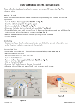
Fig. 11 Safety exhaust device, installation scheme
Connection - version A
This connection option is used if the pressure in the water line is
> 4 bar, and there is an adequate total quantity of water (bypass
water and motive water for the suction injector).
If the pressure is > 5 bar, there should be a pressure reducer (4)
installed, so that the pressure upstream of the suction injection is
between 4 and 5 bar.
Connection - version B
This connection option is used if the pressure in the water line is
> 4 bar, i.e. the prescribed pressure upstream of the suction
injection must be generated via a booster pump (6). If there is an
adequate volume of water in the supply line (5) (sufficient water
for the bypass and suction injector), the booster pump (6) can be
connected to the water supply line (5).
The water supply to the booster pump (6) can be conducted via a
separate water supply line at any time.
Caution
The system must be freely accessible on the left and
right for maintenance work (approx. 50-60 cm
space).
Note
The mounting material also contains a M6x20
countersunk screw for fixing a gas sensor, see
section 11. Accessories, underneath the reactor.
Warning
Before hydraulic connection, disconnect the system
from the mains.
Warning
If the sampling line and the solution line are
connected to the same water circuit, a non-return
valve must be fitted in the main line between the
dilution water sampling point and the injector in order
to prevent circulation of the solution with dangerous
building up of chlorine dioxide.
Caution
The motive water of the suction injector must be free
from sand and suspended matter. It is therefore
recommendable to install a dirt trap upstream of the
solenoid valve.
TM04 8203 4510
Pos. Description
1 Disposal pipe (waste water/untreated water) DN 20
2 Suction injector
3 Solenoid valve
4 Pressure reducer
5 Water supply line
6 Booster pump
%$

English (GB)
15
5.7 Electrical connection
A direct connection of the system to the power supply is made
using the terminals 1 (L1), 2 (N) and 3 (PE). Depending on the
version, the power supply can be 230 V (AC) or 115 V (AC).
5.7.1 Terminal connection diagram
Fig. 12 Terminal connection diagram
5.7.2 Power supply
5.7.3 Potential-free outputs
5.7.4 Inputs +8 V
Warning
The electrical connection must only be carried out by
qualified personnel.
Observe the local safety regulations!
Switch off the power supply before connecting the
mains cable.
Caution
Connection to an incorrect power supply may destroy
the system.
Note
Make the electrical connection according to the
enclosed connection diagram.
TM04 8204 4510
L N PE Description L N PE Description
1 2 3 Power input 16 17 18
-------------------------------------------
4 5 6 Power output 19 20 21
7 8 9 ------------------- 22 23 24 Solenoid valve/pump/bypass water
10 11 12 HCl dosing pump 25 26 27
Solenoid valve: enclosure exhaust
device
13 14 15 NaClO
2
dosing pump 28 29 30
Solenoid valve: exhaust device for
batch tank
Root NO Description Function
31 33 Fault 31/33 open in case of fault
32 34 Pre-empty signal HCl/NaClO
2
32/34 open in case of pre-empty signal
37 39 Automatic 37/39 closed in case of "system active"
38 40 Tank run dry 38/40 open in case of dry run
+8 V GND IN Description
59 (brown) 60 61 (blue) Dosing controller NaClO
2
63 (brown) 64 62 (blue) Dosing controller HCl
65 66 67 ------------------------------
69 (brown) 70 (white) 68 (green) Bypass water impeller counter

English (GB)
16
5.7.5 Inputs +12 V
5.7.6 Analog signals
+12 V GND IN Description Function
43 ------- 44 Batch tank ClO
2
overflow
NC
Contact open in case of overflow
ClO
2
level above contact
45 ------- 46 Batch tank ClO
2
max.
NO contact
Contact closed in case of "Max"
ClO
2
level above contact
47 ------- 48 Batch tank ClO
2
min.
NO contact
Contact open in case of "Min"
ClO
2
level below contact
49 ------- 50 Batch tank ClO
2
dry run
NO contact
Contact open in case of dry run
ClO
2
level below contact
51 (brown) ------- 52 (white) Pre-empty signal NaClO
2
NC
Contact open in case of pre-empty signal
NaClO
2
level below contact
------- ------- 53 (green) Empty signal NaClO
2
NC
Contact open in case of empty signal
NaClO
2
level below contact
------- ------- 54 (green) Empty signal HCl
NC
Contact open in case of empty signal
HCl level below contact
55 (brown) ------- 56 (white) Pre-empty signal HCl
NC
Contact open in case of pre-empty signal
HCl level below contact
57 ------- 58 -----------------------------------
-----------------------------------------
71 (white) 72 (brown) 73 (green) Hall sensor NaClO
2
pump
75 (white) 76 (brown) 74 (green) Hall sensor HCl pump
77 (white) 78 (brown) 79 (green)
-----------------------------------
-8180
83 - 84 Contact input water meter
85 - 86 Remote on/off Contact open: "Remote off"
87 - 88 Fault gas warning device Contact open: fault
89 - 90 Contact main water min. Contact open: min. contact main water
Shield IN/OUT Description
95 93 IN + Analog IN
96 97 OUT + Analog OUT

English (GB)
17
5.7.7 Profibus/Ethernet (option)
The controller can be optionally equipped with Profibus or
Ethernet.
Profibus-DP module
The Profibus-DP connection is made via a 6-pin plug.
Fig. 13 Profibus connection diagram
Ethernet TCP/IP
• Ethernet 10 Base-T/100 Base-TX (10/100 MBit/s).
• Transport protocol TCP or UDP connection.
• The connection is made using an RJ 45 plug of category 5.
5.8 Interfaces RS-232, -422 and -485
The controller can optionally be equipped with interfaces.
5.8.1 Connection of RS-232 interface
Fig. 14 Connection diagram of RS-232 interface
5.8.2 Connection of RS-422 and -485 interfaces
Fig. 15 Connection diagram of RS-422 and-485 interfaces
TM04 8205 4510
Plug Signal Description
0 RTS (CNTR-P/RTS) Control signal for repeater
1 PGND Shield/protective earth
2 RxD/TxD-N
Received data/transmitted data
Negative
3 RxD/TxD-P
Received data/transmitted data
Positive
4 DP GND Ground to DP 5 V
5DP 5 V
5 V supply for terminating
resistors
CNTR-N Control signal for repeater
'39
'3*1'
5['7['3
5['7['1
3*1'
576
TM04 8206 4510TM04 8207 4510

English (GB)
18
6. Operation of control electronics
6.1 Program structure
Fig. 16 Program structure
TM04 8208 4510
Automatic
Manual
operation
Logbook
Main menu
System choice Setup Service mode
Type 1, Type 2,
etc.
System type Language Venting
Batch mode Operation mode
Min. contact
water
Startup mode
Current input Units System choice Test mode
Contact input Current output
Manual control Code function
Target value
external
Reset function
Date/time
Exhaust
enclosure
Program
version
Bypass MIN
time
Auto start

English (GB)
19
6.2 Control and display elements
Fig. 17 Controller
The selection possibilities shown on the display are identified by
the numbers 1, 2, and 3, e. g.:
Menu selection is made using the keys [F1], [F2], [F3], e. g. the
function key [F1] is used to select the menu item list under "1",
etc.
Example
• Press the [F1] key to switch to the menu "Automatic".
• Press the [F2] key to switch to the submenu "Manual
operation".
• Press the [F3] key to select the menu "Logbook".
• Press the [Escape] key to return to the main menu (9).
• Press the [Enter] key to confirm an input (8).
6.3 Automatic mode
In this operation mode the capacity of the system can be
controlled automatically by incoming signals such as contact
input, current input or Bus control.
In "Manual control" mode there is no "Automatic" operation.
"Automatic" operation is activated in the main menu using the
[F1] key, and indicated by flashing on the display.
6.4 Manual operation
This operation mode facilitates the manual input of the dosing
capacity by the display in the modes current input, contact input,
manual control, or Bus control.
"Manual" operation is activated in the main menu using the [F2]
key, and indicated by flashing on the display.
6.5 Logbook
In the "Logbook" menu, all activated and acknowledged alarm
messages are recorded. The operating hours can also be called
in this menu.
• In the main menu, switch to the "Logbook" submenu using the
[F3] key (Logbook).
• Use the [F1] key to display the alarm messages (if present).
• Use the [F2] key to call all events.
• The alarm messages can be deleted, if necessary.
Switching to page 2 is possible using the [ARROW RIGHT]
key, the buffer can be deleted using the [F1] key. Switching to
page 1 is possible using the [ARROW LEFT] key.
• Use the [F3] key to display the operating hours.
Scroll in the respective menu using the [UP] and [DOWN] arrow
keys.
TM04 8209 4510
Pos. Description
1
LED for dosing controller NaClO
2
• LED flashes: dosing controller set correctly
2
LED for NaClO
2
tank
• LED off: correct level
• LED flashes: pre-empty alarm active
• LED on: empty alarm active
3
LED for bypass water
• LED on: bypass water is correct
• LED flashes: bypass water outside tolerance
4
LED for dosing controller HCl
• LED flashes: dosing controller set correctly
5
LED for HCl tank
• LED off: correct level
• LED flashes: pre-empty alarm
• LED on: empty alarm
6 Arrow keys for moving in the menus
7
Function keys
• [F1], [F2], and [F3]: select menu items
• [F4]: [Reset] key
8
[Enter] key
• Confirm inputs
9
[Escape] key
• Cancel or switch over to submenu
10 Display, 4-line
11 Master switch with [Emergency stop] function
12
LED for alarms
• LED on or flashing: present alarm
13
LED display of operation mode "automatic/manual"
• LED flashes: automatic control
14
LED for remote on/off mode
• LED flashes: remote on/off by min. contact for main
water
• LED on: remote on/off by external contact
15
LED for service mode
• LED flashes: system in [Service] menu
16
LED for alarms on the display
• LED on or flashing: present alarm
17
LED for connection of display to PLC
• LED on: connection correct
18
LED display
• LED on: display in operation
11
10
15 14 13
12
4
3
5
2
1
678
9
17
18
16
Main menu
1 Automatic
2 Manual operation
3 Logbook
Note
In order to operate the system in "Automatic" mode,
it is first necessary to select the system type and the
operation mode, see section 6.6.2 Operation modes.
Note
In order to operate the system in "Manual" mode, it is
first necessary to select the system type and the
operation mode.
Logbook
1 active alarms
2 event list
3 operating hours

English (GB)
20
6.6 System choice
Define the system size and the operation mode in the "System
choice" menu.
The input can be cancelled at any time using the [Escape] key.
The activated system type or the activated mode is displayed
flashing on the display.
6.6.1 System type
• Scroll in the main menu using the [ARROW RIGHT] key on
page 2.
• Use the [F1] key to switch to the "System choice" menu.
• In the "System choice" menu, switch to the "System type"
menu using the [F1] key.
• Select the system size using the [F1], [F2] or [F3] keys, scroll if
necessary using the [ARROW RIGHT] or [ARROW LEFT] key.
After selection of the system type, the following message is
displayed:
• Use the [Enter] or [Escape] key to return to the "System
choice" menu.
6.6.2 Operation modes
5 different operation modes can be selected:
• Batch mode
The performance of the system (100 %) is controlled by the
use of a buffer tank.
• Current input
The system performance (2.5 - 100 %) is controlled via an
external current input signal, e. g. 4-20 mA.
• Contact input
The system performance (2.5 - 100 %) is controlled via an
external contact input signal, e. g. from a contact water meter.
• Manual control
The system performance (0-100 %) is controlled by manual
input.
• Target value external
The system performance (2.5 - 100 %) is controlled via a Bus
system (can only be selected, if a bus system has been
selected in the "Basic settings > Bus" menu).
6.7 Units
Either metric or US units of measurement can be selected on the
system:
6.8 Setup
In the main menu, switch to the "Basic setting" menu using the
[F2] key (scroll if necessary).
6.8.1 Language
• In the "Basic setting" menu, switch to the "Language" menu
using the [F1] key.
• Select language using [ARROW RIGHT] or [ARROW LEFT]
key.
• Confirm using [Enter].
• Use the [Enter] or [Escape] key to return to the "Basic setting"
menu.
6.8.2 Min. contact water
The min. contact in the main water line (on site) switches the
system to standby, if the set minimum main water flow is fallen
below.
• In the "Basic setting" menu, select the "Min. contact water"
menu using the [F2] key.
• Activate or deactivate the function using the [F1] or [F2] key.
Use the [Enter] or [Escape] key to return to the "Basic setting"
menu. The selected function is displayed flashing in the "Min.
contact water" menu.
6.8.3 Current output
• In the "Basic setting" menu, select the "Current output" menu
using the [F3] key.
• Press the [F1] key to select the variable input fields.
Switching between the values (0 %; XX mA; 100 %; YY mA) is
also carried out using the [F1] key.
• Enter individual values using the [UP] and [DOWN] keys
(modify numerical values) and the [ARROW LEFT] and
[ARROW RIGHT] keys (change input position).
• Confirm the set values using the [Enter] key. The selected
current output is activated by pressing the [Enter] key again.
• Use the [Enter] or [Escape] key to return to the "Basic setting"
menu.
System type
164-XXXXD
activated
Note
The system is preset in the factory. The selected type
of system is displayed flashing in the "System
choice" menu.
Check this setting for correctness prior to starting up,
or select a new system type.
Note
Set the contact water meter in such a way that, at
max. performance the control contacts are not < 1
contact/sec.
If, in exceptional cases, this value is < 1, min. 0.25
contacts/sec., the bypass "Min" time must be
increased.
Note
The controller can process a maximum of
47 contacts/sec. If a value greater than
47 contacts/sec. is calculated, use a different contact
water meter.
Example
Default quantity of ClO
2
0.3 ppm
Main water quantity 30 m
3
/h
Contact water meter 1 contact/litre
Max. system capacity 0.3 ppm x 30 m
3
/h = 9 g/h
Contacts from water
meter
1 contact/litre x 30 m
3
/h x
1000/3600 = 8.33 contact/sec.
Note
When "Manual control" is selected, the installation
can only be started in "Manual mode". If the
installation is started in "Automatic mode", an alarm
message is displayed, and the system stops.
Note
The mode is factory-set, i.e. the selected mode is
displayed flashing in the "Operation mode" menu.
Check that this mode is correct before
commissioning; if necessary, select a new mode.
Note
The entry of the parameters for current input and
contact input is described in the Section on
"Commissioning".
Metric units US units
Bypass water [m
3
/h] Bypass water [gal/h]
System capacity [g/h] System capacity [lb/day]
Contact water meter
[contacts/litre]
Contact water meter
[contacts/gal]
Min. contact main water
activated
Current output
ClO
2
capacity
0 % = XX mA
100 % = YY mA
Current output
XX - YY mA
activated
/