
TEXAS MEMORY SYSTEMS, INC.
RamSan-325/325c
User’s Manual
Version 2.2

RamSan-325/325c User’s Manual - ii -
Any trademarks or registered trademarks used in this document belong to the companies that own
them.
Copyright © 2005, Texas Memory Systems, Inc. All rights are reserved. No part of this work may be
reproduced or used in any form or by any means - graphic, electronic, or mechanical, including
photocopying, recording, taping, or information storage and retrieval systems - without permission of
the copyright owner.

RamSan-325/325c User’s Manual - iii -
Table of Contents
Preface ................................................................................................................1
Document Overview.................................................................................................1
Conventions............................................................................................................1
Safety Precautions...................................................................................................1
Revision History ......................................................................................................2
Chapter 1 – Introduction ............................................................................................3
1.1 Overview.....................................................................................................3
1.2 System Components .....................................................................................4
1.3 Power .........................................................................................................4
1.4 Non-Volatility...............................................................................................4
1.5 Configurable Backup .....................................................................................5
1.6 Performance ................................................................................................5
Chapter 2 – Installation..............................................................................................6
2.1 Electro-Static Discharge Warning ....................................................................6
2.2 Battery Warning ...........................................................................................6
2.3 System Inspection ........................................................................................6
2.4 Rack Mounting..............................................................................................8
2.5 Connecting the Fibre Channel Ports .................................................................8
2.6 Connecting the Power Supplies .......................................................................8
2.7 Turning on the System ................................................................................10
2.8 System Initialization.................................................................................... 10
Chapter 3 – Management Tool Overview..................................................................... 12
3.1 Front Panel Display ..................................................................................... 12
3.2 Text Management Interface.......................................................................... 14
3.3 Web Management Interface.......................................................................... 17
3.4 SNMP........................................................................................................ 18
Chapter 4 – Administration Functions ......................................................................... 19
4.1 Security .................................................................................................... 19
4.2 Configuring System Date and Time................................................................25
4.3 Configuring Ethernet Settings....................................................................... 26
4.4 Power Down Settings...................................................................................32
4.5 Installing New Feature Licenses .................................................................... 34
4.6 Saving and Uploading Configuration Options................................................... 35
Chapter 5 – Monitoring Functions............................................................................... 38
5.1 Viewing System health and status................................................................. 38
5.2 Statistics ................................................................................................... 54
5.3 Logs .........................................................................................................62
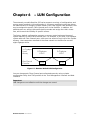
Chapter 6 – LUN Configuration .................................................................................. 65
6.1 A Example LUN Configuration ....................................................................... 66
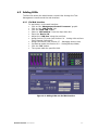
6.2 Adding LUNs ..............................................................................................67
6.3 Viewing LUN Status / LUN Map .....................................................................69
6.4 Linking LUNs to/from Fibre Channel Controllers............................................... 71
6.5 Changing LUN Numbers............................................................................... 74
6.6 Resizing LUNs ............................................................................................ 75
6.7 Managing Access Lists .................................................................................76
6.8 Deleting LUNs ............................................................................................ 79
6.9 Setting Backup Mode................................................................................... 80
6.10 Initializing LUNs.......................................................................................... 82
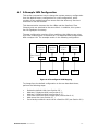
Chapter 7 Fibre Channel Controller Configuration .........................................................83
7.1 Changing Fibre Channel Topology and Link Speed............................................ 83
7.2 Configuring High Availability.........................................................................85
7.3 Resetting a Fibre Channel Controller.............................................................. 89
7.4 Clearing Fibre Channel Controller Statistics..................................................... 90
7.5 Advanced Fibre Channel Controller Options..................................................... 90

RamSan-325/325c User’s Manual - iv -
Chapter 8 – SNMP Configuration................................................................................ 92
8.1 Enabling SNMP settings ...............................................................................92
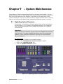
Chapter 9 – System Maintenance............................................................................... 97
9.1 Updating System Firmware ..........................................................................97
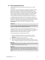
9.2 Hot Swapping Power Supplies....................................................................... 99
9.3 Hot Swapping Disk Drives .......................................................................... 100
9.4 Batteries ................................................................................................. 101
9.5 Fans ....................................................................................................... 101
Chapter 10 – Troubleshooting ................................................................................... 102
10.1 System Event Log..................................................................................... 102
10.2 Support Log............................................................................................. 102
10.3 System Diagnostics................................................................................... 102
10.4 Still Having Problems… .............................................................................. 102
Chapter 11 – Specifications ...................................................................................... 103
11.1 Physical Characteristics.............................................................................. 103
11.2 Operating Environment.............................................................................. 103
11.3 Non-operating Environment........................................................................ 103
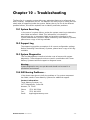
Appendix A – RamSan-325 Series Replacement Parts ................................................... 104
Appendix B – FCC/Safety Notices............................................................................... 107
Appendix C – Warranty, Maintenance, Field Service, and Repair Policy ............................ 108
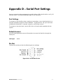
Appendix D – Serial Port Settings .............................................................................. 111
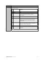
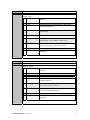
Appendix E – SNMP Trap Definitions........................................................................... 112

RamSan-325/325c User’s Manual - 1 -
Preface
Document Overview
This document provides operating procedures for the RamSan-325/325c.
It covers installation, management, and troubleshooting issues.
Conventions
This document uses the following textual conventions:
Select Front panel button descriptions
Ethernet Setup Front panel text (menu items)
lunconfig Management port (serial/Telnet) commands and
text.
Safety Precautions
PLEASE OBSERVE ALL DUE SAFETY MEASURES WHEN WORKING
WITH SENSITIVE ELECTRICAL EQUIPMENT. READ AND FOLLOW
ALL INSTRUCTIONS AND SAFETY PRECAUTIONS BEFORE
OPERATING THE UNIT.
Before servicing the unit, shutdown the unit and remove power cords
from both power supply modules. Wait 15 seconds before servicing the
unit.
DO NOT REACH INSIDE THE PROTECTIVE ENCLOSURE AFTER
REMOVING A POWER SUPPLY MODULE.
Caution for service personnel: Power supply modules include Double
Pole/Neutral Fusing.
RISK OF FIRE OR EXPLOSION IF BATTERY IS REPLACED BY AN
INCORRECT TYPE. DO NOT DISPOSE OF USED BATTERIES IN A
FIRE. THEY MAY EXPLODE. CHECK WITH LOCAL AUTHORITIES
FOR DISPOSAL INSTRUCTIONS.
Only use TMS factory certified replacement parts. Faulty components
should be replaced as soon as possible.

RamSan-325/325c User’s Manual - 2 -
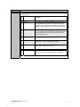
Revision History
The following table describes revisions to this document:
Version Comments Date Firmware
1.0 Initial release 08/15/2003
1.1 Added component photographs
Added information about using the help function in
the text management interface.
Added Appendix A.
09/11/2003
1.2 Updated power supply details. 10/02/2003
1.3 Added details for the RamSan-300 10/07/2003
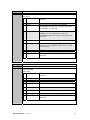
1.4 Updated Figure 2-1: RamSan-320 Layout
Added Appendix B: FCC Notice
Added Appendix C: Warranty, Maintenance, Field
Service, and Repair Policy
Added battery maintenance information to Section
2.2
Updated all system screenshots
Updated text management interface menu items
Added LED configuration to Section 3.1.1
11/21/2003
1.5 Added Section 5.1.2: Identifying a RamSan
Updated Figures 3-2, 5-1, 5-2, 5-6, and 5-10
12/08/2003
1.6 Updated Section 11.1 with voltage specs
Updated Appendix B
01/07/2004
1.7 Updated screen shots with enhanced web monitor
interface graphics
Added Section 4.2: Configuring system date and
time
Added web instructions to Section 7.2: Configuring
high availability
Added web instructions to Section 5.3.3: Clearing
logged ECC errors
Added Sections 4.3.2, 6.10, 7.3, 7.4, & 9.1
Updated Sections 1.3, 1.5, 1.6, 3.1.1, 5.1.2, 5.3,
6.2.1, 6.3.2, 6.9.2, 8.3, 8.4, and 8.5
01/28/2004
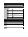
1.8 Added Section 3.4 – SNMP
Added Chapter 8 – SNMP Configuration
Added Appendix D – Serial Port Settings
Added Appendix E – SNMP Trap Definitions
Added a description of SMART technology to Section
9.3
Added Section 4.5 – Adding new feature licenses
04/28/2004 2.4.0
2.0 Updated all system screenshots 2.5.0
2.1 Added support for RamSan-325
2.2 Merged documents for RamSan-325/325c 06/01/2005 2.7.0

RamSan-325/325c User’s Manual - 3 -
Chapter 1 – Introduction
1.1 Overview
The RamSan-325 series solid-state disk uses DDR RAM (memory) as its
primary storage. This technology enables practically instantaneous data
access, which results in dramatic application performance increases.
Texas Memory Systems (TMS) designed the RamSan to be highly available
and fault tolerant. The system has higher availability than RAID or JBOD
systems because the primary storage media is DDR RAM, which does not
require moving parts. Additionally, DDR RAM has a very high mean time
between failures (as high as several hundred years) according to some
studies. The mechanical components in the RamSan are redundant and
hot swappable.
The RamSan-325’s internal disk drives provide a fully non-volatile
solution. The RamSan-325 has two modes of operation: Active Backup
TM
mode and DataSync mode. For more information on these modes, see
Section 6.9 - Setting Backup Mode.
The RamSan complements existing disk drives, JBOD, or RAID, in
performance sensitive applications. Servers perceive the RamSan as
another attached SCSI disk drive. For some applications, the RamSan is
the only storage system required. For applications that store terabytes of
data, storage administrators add the RamSan to systems that include
RAID or JBOD.
Connect the RamSan via Fibre Channel to host servers, NAS filers, or
storage network switches and hubs. If you have specific compatibility
questions, please contact Texas Memory Systems.
Use the RamSan in a variety of applications. If hard disk drives slow down
your application, there is a good chance that the RamSan can speed it up.

RamSan-325/325c User’s Manual - 4 -
1.2 System Components
The system components for the RamSan-325/325c include:
• Main system memory ranging from 16 to 64 Gigabytes (325c) or
32 to 128 Gigabytes (325)
• One to four Fibre Channel controllers
• Dual, redundant hot-swappable power supplies
• Redundant fans
• Ethernet monitoring port
• Serial monitoring port
• Front panel display for monitoring and configuration
• SNMP based monitoring
• Java-based Web monitoring
• Internal backup RAID
• Redundant batteries (N+1)
1.3 Power
The RamSan includes two power supplies. Only one power supply is
needed to run the system. The power supplies are auto-ranging (they
accept either 110 or 220 VAC power).
The RamSan-325’s power supplies are connected to an internal battery
pack. The battery pack provides up to 30 minutes of operation after a
power failure. In the event one battery or power supply fails, the other
functional power supply and battery combination handles the system
operation. You can monitor power supply temperature and voltages from
the system monitoring software.
If a RamSan-325 looses power, it operates for five minutes before
shutting down. The shutdown process involves synchronizing data to the
internal hard disk drives. If the system determines that the battery life will
not last the full shutdown delay period, it starts the synchronization
process.
When power is restored, the RamSan-325 restores system memory with
the data from the internal hard disk drives and then resumes normal
operations. In addition, the system begins recharging the batteries. You
can monitor the battery charge levels using the bundled remote
monitoring software.
1.4 Non-Volatility
By utilizing internal hard drives and batteries, the RamSan-325 combines
the performance of DDR RAM storage with the non-volatile nature of hard
disk drives. Texas Memory Systems equips the RamSan-325 with an
internal backup RAID. The backup RAID can operate at about 200 MB/sec
during operation. In order to operate the drives after a power failure
occurs, the RamSan-325 contains redundant batteries. When fully
functional and fully charged, the batteries are able to provide at least 30
minutes of operation.

RamSan-325/325c User’s Manual - 5 -
The system monitors the internal disks and batteries for a failure
condition. In such an event, it notifies the operator of an error through the
front panel display and the management software.
1.5 Configurable Backup
The RamSan-325 allows the administrator to set backup modes for each
LUN individually or system wide.
Active Backup
TM
mode (optional)
This ideal mode for most users is only available from Texas Memory
Systems. In Active Backup mode, the RamSan uses available internal
bandwidth (i.e. performance not utilized by the applications) to constantly
backup memory to the disks. The system automatically optimizes this
operation to backup the maximum amount of data at any given time
without affecting performance. This means that at any one time, most of
the data already resides on disk. Upon emergency or shutdown, the unit
need only finish the backup that is already nearly completed. Active
Backup is an optional feature on the RamSan-325; therefore, some
systems may not display this option.
Datasync mode
In DataSync mode, reads and writes are done only to memory. The disks
remain offline during normal operation. If power loss occurs and the
shutdown timer reaches zero, or the user requests a shutdown, the
system takes the Fibre Channel interfaces offline and synchronizes all data
to the internal hard drives.
None (Volatile) mode
This operational mode disables the backup functionality for the LUN
making it completely volatile. In the case of system shutdown or failure,
all data stored in the selected LUN will be lost intentionally.
1.6 Performance
The RamSan-325 series solid state disk is the ultimate in performance
storage. With up to eight Fibre Channel ports in a 3U package, the
RamSan-325 series delivers unparalleled bandwidth and I/O. The
RamSan-325 series is capable of 250,000 IOPS (I/O operations per
second) and 1,500 MB/sec of read or write performance.

RamSan-325/325c User’s Manual - 6 -
Chapter 2 – Installation
2.1 Electro-Static Discharge Warning
Important:
Please take full E.S.D. precautions if it is necessary at any time to come
into contact with any circuit boards, components or connectors.
Electrostatic discharge can damage the components used in the RamSan
and its interfaces.
2.2 Battery Warning
The internal batteries in the RamSan-325 are charged with enough
voltage to power a fully loaded system for approximately 30 minutes.
However, the batteries may not be fully charged when you install your
system. Therefore, ensure that your batteries are fully charged before you
use the system where there is risk of power failure.
The following battery charge times apply to a fully loaded RamSan-325:
With one hour of charge time, the batteries provide nine minutes of
runtime. With two hours of charge time, the batteries provide 17 minutes
of runtime. With three hours of charge time, the batteries provide 20
minutes of runtime.
As a precaution, replace the RamSan’s batteries every two years. To
obtain spare or new batteries for your RamSan, contact Texas Memory
Systems.
2.3 System Inspection
TMS ships the RamSan with a packing list. Ensure that you have received
all of the components listed.
1) Examine the external chassis for any damage that might have
occurred during shipping.
2) Ensure that both power supplies are locked securely in place and that
the internal hard disk drives have not come loose.
3) Inspect the interface plate for any screws that might have loosened
during shipping.
4) Inspect the front panel display for damage.
5) Report any meaningful damage to Texas Memory Systems.
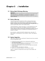
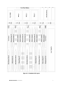
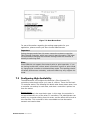
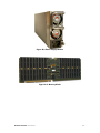
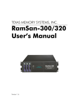
Figure 2-1 shows an overhead view of the layout of the RamSan-325
components.

RamSan-325/325c User’s Manual - 7 -
Figure 2-1: RamSan-325 Layout

RamSan-325/325c User’s Manual - 8 -
2.4 Rack Mounting
The RamSan-325 series solid state disk is a 3U rack-mountable system.
TMS ships the system with the slides and equipment needed to install it
into a standard 19” rack.
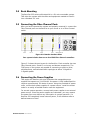
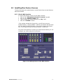
2.5 Connecting the Fibre Channel Ports
After you have inspected the system and properly mounted it, connect the
Fibre Channel ports on the RamSan to your server or to a Fibre Channel
switch.
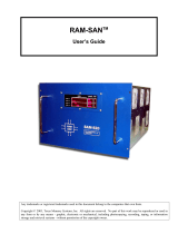
Figure 2-2: RamSan Interface Plate
Your system includes from one to four FC65 Fibre Channel controllers.
Figure 2-2 shows the port layout for the RamSan. Each controller has two
Fibre Channel ports: A and B, on the top and bottom respectively. The
FC65 ports on the system are capable of connecting to point-to-point,
arbitrated loop, and switched fabric topologies at either 2-Gigabit or
1-Gigabit speeds.
2.6 Connecting the Power Supplies
TMS equips the RamSan with dual redundant hot-swappable power
supplies that operate on 110/220 VAC line power. A fully loaded RamSan
requires approximately 350 watts of power. Using the provided AC power
cords, connect both power supplies to a power source. Install the socket
outlet in an easily accessible location near the equipment.
For normal system operation, connect both power supplies to an external
power source. Since the power supplies are redundant, you may remove
line power from one without any interruption in system operation. If a
RamSan-325 completely looses external power, it will shutdown after a
defined amount of time.
FC 3 FC 4 FC 2 FC 1 Gbit Ethernet

RamSan-325/325c User’s Manual - 9 -
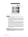
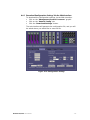
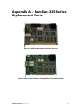
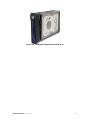
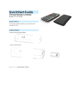
Figure 2-3 RamSan Power Supply
The power supply includes the following button and indicators:
“Power” switch
The large black button above the power supplies acts as an on/off switch
and will silence the warning buzzer.
• The button provides a means to activate the power supplies (turn
them on) after a system shutdown. If the system shuts down for
any reason other than a power failure, press the “Power” switch to
turn the system back on. If power is restored after a power failure
or both power cords are removed and then reinserted, the system
automatically powers on.
• When a power supply fails, is removed, or looses AC power, the
power supplies beep. If the buzzer sounds, silence it by pressing
the “Power” switch once or by correcting the problem. The silencing
lasts until the problem is corrected. Once the problem is corrected,
the buzzer will sound again if another power failure occurs.
• In addition, the button allows the user to force a hard-shutdown of
the system. Only perform a hard-shutdown when you are unable to
perform a manual shutdown and after backing up all of the data to
external storage. To perform a hard-shutdown, unplug or remove
both power supply modules. Then, hold down the “Power” switch
for approximately 5 seconds to shutoff the batteries and cause the
system to lose power.
Warning:
A hard-shutdown will cause data loss and should only be used when
the user is unable to perform a manual shutdown and all the data has
been backed up to external storage.
“Power”
AC Volta
g
e

RamSan-325/325c User’s Manual - 10 -
AC Voltage indicator light
When the power supply is connected to AC power and is operating
properly, the indicator light attached to each power supply is green. If the
green light is not on, either the power supply is disconnected from an AC
power source or the power supply has failed. Check the power cable to
determine if power has been lost to the supply or whether the supply has
failed. The front panel display, Text Management Interface, or Web
interface, may provide additional information regarding the problem.
2.7 Turning on the System
The RamSan automatically powers on when power is connected to the
system. The only time the system does not power on automatically is
when a user has initiated a manual shutdown or the system has powered
off due to some failure other than AC power loss. In the event this
happens, press the “Power” button, which is the large black button above
the power supplies. Please see Section 2.6 Connecting the Power Supplies.
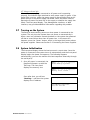
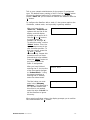
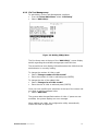
2.8 System Initialization
The front panel display shows the boot process’s current state. Once the
power is connected, the system turns on automatically and the front panel
display begins the power on sequence. The following happens
automatically (you can also monitor this boot sequence externally through
the serial port):
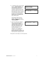
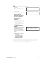
1. Once AC power is connected, the
RamSan will power-up with the
TMS logo. The front panel
displays the memory size.
Soon after that, you will see
“Booting…” and then the system
displays the IP address.
TMS
|
|
|
|
|
|
||||||
()
Texas Memory Systems
TMS
|
|
|
|
|
|
||||||
()
Memory Size: 128GB
Booting ...
IP Address Acquired:
000.000.000.000

RamSan-325/325c User’s Manual - 11 -
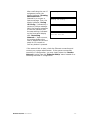
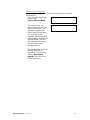
2. In a RamSan-325, the front panel
displays “Restoring Data” and
cycles between a progress bar
and an estimated time until
completion. Administrators may
use this to determine how much
time before the system is on-line.
This information is also available
through the Text Management
Interface. This process will take
approximately 12 minutes for a
fully loaded system.
If all system LUNs are set to
Volatile mode, the front panel
displays “Initializing” instead of
“Restoring Data.”
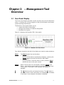
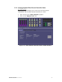
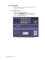
3. Once the system has restored
data, the front panel displays
“System Status: GOOD” and
shows the performance bars for
each Fibre Channel port. The
numbers represent the Fibre
Channel Controllers. If a
controller is not installed, the
number and corresponding
performance will not display. The
top bars represent the port A and
the bottom bars represent port B.
The system is now ready for normal operation.
Restoring Data ... 73.8%
Est. Time Left 04:03
System Status: GOOD
1==- 2=-- 3- 4===
Restoring Data ... 73.8%

RamSan-325/325c User’s Manual - 12 -
Chapter 3 – Management Tool
Overview
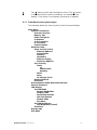
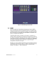
3.1 Front Panel Display
The Front Panel Display provides a quick and easy way view the RamSan’s
status. It displays the current progress of disk synchronization and shows
system warnings and failures.
The RamSan’s front panel allows you to:
• Inspect the state of the system
• Change the method of IP address assignment
• Shutdown the system
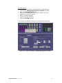
Figure 3-1 displays the RamSan-325’s front panel:
Figure 3-1: RamSan-325 Front Panel
Four buttons located to the left of the display are used to make selections:
Menu The Menu button has two functions:
• Function 1:
On any of the status or performance displays, pressing the
“Menu
” button launches the RamSan Main Menu.
• Function 2:
Escape function. Once the menu is open, pressing “Menu
”
returns the user to the prior screen.
Select
When a menu item is on the display, pressing “Select” will
either: execute that menu option or proceed to the next layer
in the menu. If the menu is not selected, this button is
disabled.
↑
The “↑” button scrolls up through the menu. The “↑” button is
also used cancel certain commands, as indicated on the display.
If the menu is not selected, this button is disabled.

RamSan-325/325c User’s Manual - 13 -
↓ The “↓” button scrolls down through the menu. The “↓” button
is also used confirm certain commands, as indicated on the
display. If the menu is not selected, this button is disabled.
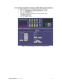
3.1.1 Front Panel menu system layout
The following details the menu system of the front panel display:
Main Menu
System Information
Firmware Version
Memory Size
LUNs Configured
IP Address
# of Controllers
FC Firmware
System Uptime
Ethernet Setup
Show Current Config
Ethernet Address
Subnet Mask
Gateway
Hostname
Ethernet Config
Hardware Address
Set IP Config
Static
IP
Subnet Mask
Gateway
DHCP
None
No Change (Exit)
Restart Network
Exit Menu
Active Monitor Mode/Deactivate Monitor
Manual Shutdown
LED Display
Set LED Mode
Display Bandwidth
Display IOPS
Performance Demo
LED Test Pattern
Disable LEDs
Exit Menu
Set LED Brightness
LED Brightness [Level]
Exit Menu
Display logo
Exit Menu

RamSan-325/325c User’s Manual - 14 -
3.2 Text Management Interface
The RamSan’s management port allows you to manage, configure, and
monitor system behavior.
You may connect to the management port with either a DB-9 serial cable
or an RJ-45 Ethernet cable.
3.2.1 Connecting using a terminal program
To connect to the RamSan using a serial port connection, use a
dumb terminal or a terminal emulation program such as Windows™
HyperTerminal. Set your baud rate to 9600 with 8 data bits, 1 stop
bit, no parity, and no flow control.
To connect to the serial port, use the DB-9 non-null serial cable
supplied with the system.
3.2.2 Connecting using Telnet
Once the administrator configures the Ethernet port on the
RamSan using either the front panel or the serial port, you may
remotely monitor the system using a Telnet session. Set your
terminal settings to VT100 mode.
In order to use the Ethernet port, first configure the IP address for
the RamSan by using the front panel display or from the serial
port. For complete instructions for configuring the Ethernet, please
refer to Section 4.3 – Configuring Ethernet Settings.
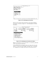
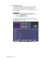
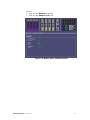
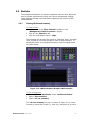
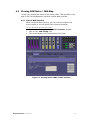
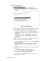
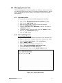
3.2.3 General interface layout and instructions
TMS designed the management program as a text based GUI. This
program displays all of the user’s possible choices in a series of
menus. The user may select menu items by entering the number of
the menu item or by using the arrow keys and the [ENTER] key.
For a detailed description of each menu item, arrow down to the
item and press the [H] key to display help text.

RamSan-325/325c User’s Manual - 15 -
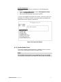
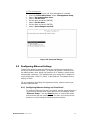
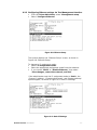
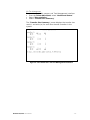
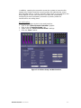
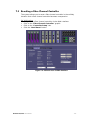
Figure 3-2: Text Management Interface
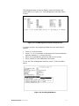
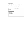
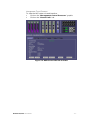
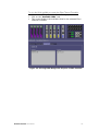
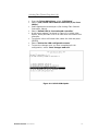
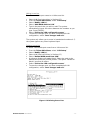
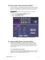
When the user selects some menu items, the program displays
sub-menus, as shown in Figure 3-3: Text Management Interface
Sub-Menu:
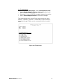
Figure 3-3: Text Management Interface Sub-Menu
When in a sub-menu, the user can select “C” to cancel or press the
“ESC” key to return to the menu.
Once satisfied with the changes made on a menu, the user must
select “S” to save all of the changes. Pressing “ESC” or selecting
“Q” disregards any changes and returns to the previous menu.

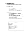
RamSan-325/325c User’s Manual - 16 -
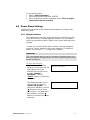
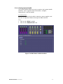
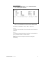
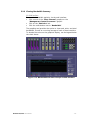
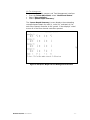
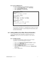
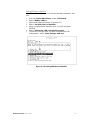
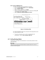
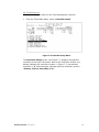
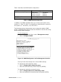
TMS designed some screens to display status information and
display data as in Figure 3-4: Text Management Interface Status
Screen:
Figure 3-4: Text Management Interface Status Screen
On status screens, the program provides the user with several
options:
• Press ‘Q’ to exit the menu
• Press ‘I’ or ‘D’ to increment or decrement the interval between
statistics updates in ¼ second intervals
• Enter ‘R’ to immediately refresh the data on the screen
• Enter [SPACE] to view additional information
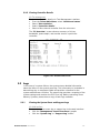
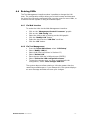
To exit the Text management interface, enter ‘Q’ from the Main
Menu.
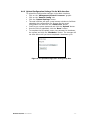
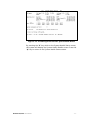
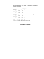
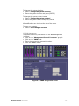
Figure 3-5: Scrolling Sub-Menus
Page is loading ...
Page is loading ...
Page is loading ...
Page is loading ...
Page is loading ...
Page is loading ...
Page is loading ...
Page is loading ...
Page is loading ...
Page is loading ...
Page is loading ...
Page is loading ...
Page is loading ...
Page is loading ...
Page is loading ...
Page is loading ...
Page is loading ...
Page is loading ...
Page is loading ...
Page is loading ...
Page is loading ...
Page is loading ...
Page is loading ...
Page is loading ...
Page is loading ...
Page is loading ...
Page is loading ...
Page is loading ...
Page is loading ...
Page is loading ...
Page is loading ...
Page is loading ...
Page is loading ...
Page is loading ...
Page is loading ...
Page is loading ...
Page is loading ...
Page is loading ...
Page is loading ...
Page is loading ...
Page is loading ...
Page is loading ...
Page is loading ...
Page is loading ...
Page is loading ...
Page is loading ...
Page is loading ...
Page is loading ...
Page is loading ...
Page is loading ...
Page is loading ...
Page is loading ...
Page is loading ...
Page is loading ...
Page is loading ...
Page is loading ...
Page is loading ...
Page is loading ...
Page is loading ...
Page is loading ...
Page is loading ...
Page is loading ...
Page is loading ...
Page is loading ...
Page is loading ...
Page is loading ...
Page is loading ...
Page is loading ...
Page is loading ...
Page is loading ...
Page is loading ...
Page is loading ...
Page is loading ...
Page is loading ...
Page is loading ...
Page is loading ...
Page is loading ...
Page is loading ...
Page is loading ...
Page is loading ...
Page is loading ...
Page is loading ...
Page is loading ...
Page is loading ...
Page is loading ...
Page is loading ...
Page is loading ...
Page is loading ...
Page is loading ...
Page is loading ...
Page is loading ...
Page is loading ...
Page is loading ...
Page is loading ...
Page is loading ...
Page is loading ...
Page is loading ...
Page is loading ...
Page is loading ...
Page is loading ...
Page is loading ...
-
 1
1
-
 2
2
-
 3
3
-
 4
4
-
 5
5
-
 6
6
-
 7
7
-
 8
8
-
 9
9
-
 10
10
-
 11
11
-
 12
12
-
 13
13
-
 14
14
-
 15
15
-
 16
16
-
 17
17
-
 18
18
-
 19
19
-
 20
20
-
 21
21
-
 22
22
-
 23
23
-
 24
24
-
 25
25
-
 26
26
-
 27
27
-
 28
28
-
 29
29
-
 30
30
-
 31
31
-
 32
32
-
 33
33
-
 34
34
-
 35
35
-
 36
36
-
 37
37
-
 38
38
-
 39
39
-
 40
40
-
 41
41
-
 42
42
-
 43
43
-
 44
44
-
 45
45
-
 46
46
-
 47
47
-
 48
48
-
 49
49
-
 50
50
-
 51
51
-
 52
52
-
 53
53
-
 54
54
-
 55
55
-
 56
56
-
 57
57
-
 58
58
-
 59
59
-
 60
60
-
 61
61
-
 62
62
-
 63
63
-
 64
64
-
 65
65
-
 66
66
-
 67
67
-
 68
68
-
 69
69
-
 70
70
-
 71
71
-
 72
72
-
 73
73
-
 74
74
-
 75
75
-
 76
76
-
 77
77
-
 78
78
-
 79
79
-
 80
80
-
 81
81
-
 82
82
-
 83
83
-
 84
84
-
 85
85
-
 86
86
-
 87
87
-
 88
88
-
 89
89
-
 90
90
-
 91
91
-
 92
92
-
 93
93
-
 94
94
-
 95
95
-
 96
96
-
 97
97
-
 98
98
-
 99
99
-
 100
100
-
 101
101
-
 102
102
-
 103
103
-
 104
104
-
 105
105
-
 106
106
-
 107
107
-
 108
108
-
 109
109
-
 110
110
-
 111
111
-
 112
112
-
 113
113
-
 114
114
-
 115
115
-
 116
116
-
 117
117
-
 118
118
-
 119
119
-
 120
120
-
 121
121


Texas Memory Systems RamSan-325/325c User manual
- Type
- User manual
- This manual is also suitable for
Ask a question and I''ll find the answer in the document
Finding information in a document is now easier with AI
Related papers
-
 Texas Memory Systems 320 User manual
-
 Texas Memory Systems Power Supply RamSan-300/320 User manual
-
 Texas Memory Systems RamSam-210 User manual
-
 Texas Memory Systems RamSan-810 User manual
-
 Texas Memory Systems RamSan-300/320 User manual
-
 Texas Memory Systems RamSan-500 User manual
-
 Texas Memory Systems RAM-SAN 520 User manual
-
 Texas Memory Systems RAM-SAN 520 User manual


Other documents
-
BTF-LIGHTING BTF-LIGHTING WB5 WiFi 5-in-1 Smart LED Strip Controller User manual
-
Qlogic SANbox 5600 Series Supplementary Manual
-
 YoSmart KT-LR-U01B User manual
-
Boston VS 336 Owner's manual
-
VIAIR 450C User manual
-
VIAIR 32530 User manual
-
Promise Technology VTrak S3000 User manual
-
IBM DS6000 Series User manual
-
Proware EP-2123S-F4S3 User manual
-
