Page is loading ...

TEXAS MEMORY SYSTEMS, INC.
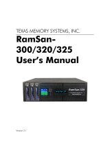
RamSan-500
User’s Manual
Version 1.2
RamSan-500

RamSan-500 User’s Manual 2 of 48
Revision History
Revision HistoryRevision History
Revision History
The following table describes revisions to this document:
Version Comments Date
1.0 Initial release 9/14/2007
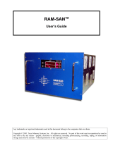
Any trademarks or registered trademarks used in this document belong to the companies that own them.
Copyright © 2007, Texas Memory Systems, Inc. All rights are reserved. No part of this work may be reproduced or
used in any form or by any means - graphic, electronic, or mechanical, including photocopying, recording,
taping, or information storage and retrieval systems - without permission of the copyright owner.

RamSan-500 User’s Manual 3 of 48
Table of Contents
Chapter 1 – Introduction .................................................................................. 4
1.1 Overview ............................................................................................... 4
1.2 System Components ............................................................................... 4
1.3 Power ................................................................................................... 4
1.4 Reliability .............................................................................................. 5
1.5 System Management .............................................................................. 5
Chapter 2 – Reviewing your shipment ................................................................ 6
2.1 Unpacking ............................................................................................. 6
2.2 System Overview.................................................................................... 6
Chapter 3 – Connections .................................................................................. 8
3.1 Installing a Host Bus Adaptor in the Host System ....................................... 8
3.2 Connecting the Fibre Channel Ports........................................................... 9
3.3 Connecting to a Network ........................................................................10
3.4 Connecting Power to the System .............................................................11
Chapter 4 – Getting Started.............................................................................12
4.1 Turning on the System ...........................................................................12
4.2 System Initialization ..............................................................................12
4.3 Front Panel Display Basics ......................................................................13
4.4 Controlling System Power with the Front Panel Display...............................14
4.5 Network Configuration with the Front Panel Display ...................................17
4.6 Additional System Management Options ...................................................20
4.7 Web Monitor Basics................................................................................21
4.8 Date and time setup with the Web monitor ...............................................24
4.9 Network Configuration with the Web Monitor.............................................25
4.10 Managing security with the Web Monitor .................................................26
4.11 Basic LUN Creation...............................................................................28
4.12 Viewing the Logs with the Web Monitor...................................................32
4.13 Upgrading the System with the Web Monitor ...........................................36
4.14 If the System has a Problem .................................................................37
Chapter 5 – System Maintenance .....................................................................39
5.1 Contacting Texas Memory Systems ..........................................................39
5.2 Power Supplies......................................................................................39
5.3 Flash Modules .......................................................................................41
5.4 Fans ....................................................................................................46
5.5 Batteries ..............................................................................................48

RamSan-500 User’s Manual 4 of 48
Chapter 1 – Introduction
1.1 Overview
The RamSan-500 is the World’s Fastest Flash-based storage system. The
basic unit contains nine RAID-protected Flash storage modules accessible
from the front, with a combined usable capacity of either 1 or 2-Terabytes
and a data bandwidth of 2 GB/sec. A single RamSan-500 fits in 4U of rack
space. Multiple RamSan-500 units scale capacity, bandwidth, and IOPS.
1.1.1
1.1.11.1.1
1.1.1 High
High High
High P
PP
Performance
erformance erformance
erformance Solid
SolidSolid
Solid-
--
-S
SS
State
tate tate
tate S
SS
Storage
toragetorage
torage
Unlike other mass storage products, the RamSan-500 is not based on
mechanical rotating disk technology, but instead on high performance
memory technology. While each of the nine Flash storage modules may
look like a disk, there are no moving parts and it operates with a much
faster protocol, reducing access time and increasing the data transfer rate.
This is achieved with the use of better connectors (rugged, more data
pins) and a simple transfer protocol.
While the capacity and throughput of the RamSan-500 is impressive, the
key to the system’s power resides in its I/O structure. The RamSan-500
can be configured with 2-8 Fibre Channel (FC) ports. Internally, it can
handle the bandwidth and supply the IOPS needed for emerging storage
applications.
1.1.2
1.1.21.1.2
1.1.2 Easy
Easy Easy
Easy I
II
Installation and
nstallation and nstallation and
nstallation and C
CC
Configuration
onfigurationonfiguration
onfiguration
The RamSan-500 is easy to install on a Fibre Channel SAN or directly
attached to a server. Most common parameters, including the
management Ethernet port, can be set from the front panel. The
RamSan-500 also has monitoring and configuration capabilities
through a Web browser.
1.2 System Components
The system components for the RamSan-500 include:
9 Flash modules with 1 or 2 Terabytes of data storage capacity
16-64 GB DDR Cache
4 dual-ported 4G-bit Fibre Channel Controllers
Hot-swappable redundant power supplies
Easily replaceable fans
Front panel display for monitoring and configuration
Java-based monitoring
1.3 Power
The RamSan-500 includes two hot-swappable power modules that are
auto-ranging (they accept either 110 or 220 VAC power).

RamSan-500 User’s Manual 5 of 48
1.4 Reliability
The RamSan-500 is designed to offer superior reliability to other solid-
state disks and RAID devices. Its standard features include Chipkill™-
protected RAM, hot-swap modular Flash memory, hot-swap power
supplies, failover ports, and SNMP compatibility. The nine-unit RAID
design ensures data integrity even in the event of the complete failure of
a single Flash module. In order to reduce the probability of a Flash module
failure, the unit incorporates multiple error-correcting methods.
1.5 System Management
Basic management operations, including manual shutdown and alerts, are
available from the front panel screen. Full monitoring and configuration
capabilities are available over any browser via a password protected Java
applet. The RamSan-500 also offers Telnet management capabilities and
is fully SNMP compatible.

RamSan-500 User’s Manual 6 of 48
Chapter 2 – Reviewing your
shipment
2.1 Unpacking
2.1.1
2.1.12.1.1
2.1.1 System
System System
System I
II
Inspection
nspectionnspection
nspection
TMS ships the RamSan-500 with a packing list. Ensure that you have
received all of the components listed.
1) Examine the external chassis for any damage that might have
occurred during shipping.
2) Examine the Flash modules to ensure that they were not damaged
during shipping.
3) Inspect the interface plate for any screws that might have loosened
during shipping.
4) Inspect the front panel display for damage.
5) Report any meaningful damage to Texas Memory Systems.
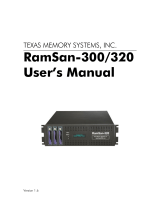
2.2 System Overview
All nine Flash storage modules can be quickly accessed from the front
of the RamSan-500. Each module has an interlocking system with the
look and feel of a typical disk drive. The Flash module can be removed
while system power is on, once the module has been selected to go
off-line (indicated when both module LEDs are off). Additionally, all
nine Flash modules can be removed and reinstalled into another
RamSan-500 unit.
Figure 1 – RamSan-500 Front

RamSan-500 User’s Manual 7 of 48
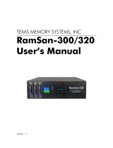
Figure 2 – RamSan-500 Back
2.2.1
2.2.12.2.1
2.2.1 Rack mounting
Rack mountingRack mounting
Rack mounting
The RamSan-500 solid-state disk (SSD) system is a 4U rack-mountable
system. TMS ships the system with the slides and equipment needed to
install it into a standard 19” rack.

RamSan-500 User’s Manual 8 of 48
Chapter 3 – Connections
3.1 Installing a Host Bus Adaptor in the Host System
Host Bus Adapters (HBAs) provide an interface from the server’s PCI bus
to Fibre Channel attached devices. HBAs are available from a variety of
vendors. Before purchasing an HBA, ensure that it provides a driver for
the Operating System (OS) version that you are using.
Before installing the HBA, consult your server’s documentation to
determine which one of its PCI slots is on the fastest and least congested
PCI bus (see Section 3.1.3, below, for details). Next, power down your
server and place the HBA in this slot. Power on your server and follow the
instructions provided with the HBA to install the driver. It is generally a
good idea to check the HBA provider’s Web site to obtain the latest drivers
and firmware for the HBA. Updated drivers may include new features,
improved performance, and minor bug fixes.
T
ROUBLESHOOTING
T
IP
:
I
F YOU ENCOUNTER ANY PROBLEMS WITH THE
HBA,
THE FIRST STEP IN THE DEBUGGING
PROCESS IS VERIFYING THAT YOU ARE USING THE LATEST DRIVER AND FIRMWARE
.
The speed of the server and network interface ultimately limit the
RamSan-500’s capabilities. A few different components can affect the
maximum performance of the RamSan-500, including FC interfaces, Host
Bus Adapters, PCI buses, and server CPU resources.
3.1.1
3.1.13.1.1
3.1.1 Fibre Channel
Fibre Channel Fibre Channel
Fibre Channel I
II
Interface
nterfacenterface
nterface
Currently, the RamSan supports two Fibre Channel communication
speeds: 2- and 4-gigabit. Accounting for encoding and overhead, these
transfer rates allow data to be transmitted to the RamSan-500 at a
half duplex rate of ~200 MB/s and ~400 MB/s, for 2- and 4-gigabit,
respectively. Fibre Channel interfaces have separate read and write
connections that allow a maximum data rate of twice the half-duplex
rate. To sustain the maximum full duplex rate, the data usage pattern
of the system must be 50% read and 50% write (due to the individual
half duplex limits). To find the maximum for other data usage patterns,
use the following formula (4-gigabit HBA):
( Smaller usage percentage / Larger ) x 400MB/s + 400MB/s
For example, to calculate a data usage pattern with 66% reads and
33% writes:
( 33 / 66 ) x 400 + 400 = 600 MB/s
Many applications require storage bandwidth that exceeds what a
single FC connection can provide. To accommodate this situation, we
provide up to 8 FC ports per RamSan-500, each of which can supply
the bandwidth described above. Using multiple Fibre Channel

RamSan-500 User’s Manual 9 of 48
connections requires one of the following solutions: multi-pathing
software to a single LUN, using software to stripe across multiple LUNs,
accessing multiple LUNs on the RamSan-500 concurrently, or
connecting multiple servers to the system.
3.1.2
3.1.23.1.2
3.1.2 Host Bus Adapter
Host Bus AdapterHost Bus Adapter
Host Bus Adapter
You can modify some HBA settings to increase performance. For
information specific to your HBA, consult the HBA documentation. Note
that many settings are intended to increase the performance of slow
storage devices and will not be applicable to RamSans. It is always
advisable to check the frame size. The amount of overhead for each
Fibre Channel frame is fixed, so larger frames have lower overhead.
Set the frame size to the maximum setting, generally 2048 bytes.
3.1.3
3.1.33.1.3
3.1.3 PCI
PCI PCI
PCI B
BB
Bus
usus
us
High bandwidth HBA traffic can quickly inundate slower PCI buses.
Once a PCI bus reaches its limit, you can do very little to improve
performance. Many servers, however, provide different PCI buses with
different speeds, and placing the HBA on a different PCI bus can
improve performance. TMS recommends giving each 4-gigabit 2 port
HBA at least an entire PCIX bus or a PCI Express (PCIe) slot.
3.1.4
3.1.43.1.4
3.1.4 C
CC
CPU
PUPU
PU
At a certain point, CPU performance can limit data transfer rates.
Determine whether the server’s CPU resources are the limiting factor
in performance while benchmarking the RamSan-500 as a raw physical
device. Otherwise, an improperly tuned file system or application can
make the CPU appear to be the limiting factor when it is not. Perform
raw device testing after setting up any multi-pathing.
There are a few ways to decrease CPU usage without increasing CPU
resources. Certain data usage patterns can be very CPU intensive and
fully utilize the CPU. These usually involve small transfer sizes. When
possible, increasing the average transfer size decreases CPU usage
and offers better performance. Another way to decrease CPU usage is
by enabling interrupt coalescing. Interrupt coalescing is an HBA
dependent feature that offers a method to trade latency for CPU usage.
This feature delays calling the HBA transfer interrupt until several
transfers are ready. In general, TMS does not recommend enabling
Interrupt Coalescing, because most RamSan applications benefit from
low latency. For more information, consult your HBA documentation.
3.2 Connecting the Fibre Channel Ports
Connect the Fibre Channel ports on the RamSan-500 to your server or to
a Fibre Channel switch.

RamSan-500 User’s Manual 10 of 48
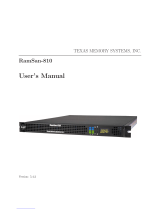
Figure 3– Fibre Channel Port Locations
Figure 3– Fibre Channel Port Locations shows the port layout for the
RamSan-500. Each controller has two or four Fibre Channel ports: A and B,
on the top and bottom respectively. The FC-77 ports on the system are
capable of connecting to point-to-point, arbitrated loop, and switched
fabric topologies at either 4-Gigabit or 2-Gigabit speeds.
3.3 Connecting to a Network
Your RamSan-500 includes a Gigabit Ethernet port for remote
management over a network. You use this connection to configure the
storage and management features.
Figure 4 – Gigabit Ethernet Port Location
Fibre Channel Ports
Ethernet Port

RamSan-500 User’s Manual 11 of 48
3.4 Connecting Power to the System
A fully loaded RamSan-500 requires approximately 250 watts of power. It
contains redundant power supplies that are hot-swappable. Using the AC
power cords provided, connect each power module to a power source.
Install the socket outlet in an easily accessible location near the
equipment.
Figure 5 – RamSan-500 Power Supply
The power supply includes the following button and indicators:
3.4.1
3.4.13.4.1
3.4.1 Power
Power Power
Power S
SS
Switches
witcheswitches
witches
Each power module has an individual on/off switch and power indicator
light.
W
ARNING
:
A
HARD
-
SHUTDOWN WILL CAUSE DATA LOSS AND SHOULD ONLY BE USED WHEN
YOU ARE UNABLE TO PERFORM A MANUAL SHUTDOWN AND BACK UP ALL DATA TO THE
F
LASH MODULES OR EXTERNAL STORAGE
.
3.4.2
3.4.23.4.2
3.4.2 AC
AC AC
AC Voltage I
Voltage IVoltage I
Voltage Indicator
ndicator ndicator
ndicator L
LL
Light
ightight
ight
When the power supply is connected to AC power and is operating
properly, the indicator light attached to each power supply is green. If
the green light is not on, either the power supply is disconnected from
an AC power source or the power supply has failed. Check the power
cable to determine if power has been lost to the supply or the module
has failed. The front panel display or Web monitor may provide
additional information regarding the problem.
Power Supplies

RamSan-500 User’s Manual 12 of 48
Chapter 4 – Getting Started
This chapter will guide you through setting up your RamSan-500. It is
important to accomplish the following tasks to make your system usable:
Use the front panel display to set up the network (Section 4.5)
Get the Web monitor operational (Section 4.7)
Use the Web monitor to set the date and time (Section 4.8)
Use the Web monitor to configure advanced network settings (Section
4.9)
Use the Web monitor to configure security (Section 4.10)
Other sections explore the configuration tools and should be read to
familiarize you with the system.
4.1 Turning on the System
Separate power cables should be connected to each of the two RamSan-
500 power modules. The 3-prong AC inlet lies at the bottom of each power
module. To power on the system, both power modules should be switched
on. Though the RamSan-500 will operate when only one power supply is
switched on, this is not recommended. After a user-initiated shutdown,
switch both power modules off, then switch both modules on again to
bring the system back on-line.
4.2 System Initialization
The front panel display shows the boot process’ current state. Once the
power is connected, the system turns on automatically and the front panel
display begins the power-on sequence. The following happens
automatically:
System Status: GOOD
1 2 3 4
Once AC power is connected, the
RamSan will power-up and the
front panel displays “System
Status: GOOD” and shows the
performance bars for each Fibre
Channel port. The numbers
represent the Fibre Channel
Controllers. If a controller is not
installed, the number and
corresponding performance will not
display. The top bars represent
port A and the bottom bars
represent port B.
The system is now ready for normal operation.

RamSan-500 User’s Manual 13 of 48
4.3 Front Panel Display Basics
The front panel display provides a quick and easy way to view the
RamSan-500’s status. It displays the current progress of Flash module
synchronization and shows system warnings and failures.
The RamSan-500’s front panel allows you to:
Inspect the state of the system
Select a Flash module to power off
Change the method of IP address assignment
Reboot/Shutdown the system.
Four buttons located to the left of the display are used to make selections:
Menu: This button has two functions. On any of the status or
performance displays, pressing this button launches the RamSan Main
Menu. It is also used as an escape function. Once the menu is open,
pressing it returns the user to the prior screen.
Select: When a menu item is on the display, pressing this button will
either execute that menu option or proceed to the next layer in the menu.
If the menu is not selected, this button is disabled.
↑
↑↑
↑: This button scrolls up through the menu. It is also used to cancel
certain commands, as indicated on the display. If the menu is not selected,
this button is disabled.
↓
↓↓
↓: This button scrolls down through the menu. It is also used to confirm
certain commands, as indicated on the display. If the menu is not selected,
this button is disabled.
You can scan through the first level of options on the RamSan by pressing
the Menu key.
Main Menu
System Info
Selecting “System Info”
displays information about your
RamSan-500.
Main Menu
System Log
Selecting “System Log” allows
you to clear your system log.
See Section 4.15.2 for more
information.
Main Menu
Network Config
Selecting “Network Config”
allows you to connect your
RanSan-500 to your network.
See Section 4.9 for more
information.

RamSan-500 User’s Manual 14 of 48
Main Menu
Flash Module
Selecting “Flash Module” allows
you to select a module to identify
mode or for power off.
Main Menu
Active/Remove Monitor Mode
Selecting “Active Monitor
Mode” changes the default front
panel display to show port
activity across both display lines.
This makes it easier to view from
a distance. This option becomes
“Remove Monitor Mode” once
it has been set.
Main Menu
LED Config
Selecting “LED Config” gives
you a variety of options for
controlling the LEDs on the upper
left-hand side of the front of the
RamSan-500.
Main Menu
Display/Disable Logo
Selecting “Display Logo”
displays the TMS logo on the
front panel display. This option
becomes “Disable Logo” once it
has been set.
Main Menu
Manual Restart
Selecting “Manual Restart”
reboots your RamSan-500. See
Section 4.4.2 for more
information.
Main Menu
Manual Shutdown
Selecting “Manual Shutdown”
turns off your RamSan-500. See
Section 4.4.1 for more
information.
4.4 Controlling System Power with the Front Panel Display
The RamSan-500 has features that allow the administrator to safely power
down the system. Before powering down the system, un-mount the drives
from your OS. Do not turn off the system by unplugging the power cords.
4.4.1
4.4.14.4.1
4.4.1 Manual
Manual Manual
Manual S
SS
Shutdown
hutdownhutdown
hutdown
The administrator can shut down the RamSan-500 manually from the
front panel display. This procedure safely synchronizes all data in the
RAM cache to the internal Flash module storage.
In order to turn the RamSan-500 back on after a manual shutdown,
switch off both power modules and then switch both back on.

RamSan-500 User’s Manual 15 of 48
Main Menu
Manual Shutdown
To shut down the system using
the front panel, use the arrow
buttons to cycle through the
top-level menu to select
“Manual Shutdown”. Use the
Select button to select this
menu item.
Power Off System?
↓ Yes ↑ No
The display prompts you to
confirm that you wish to
“Power Off System”. To
cancel the shutdown, use the ↑
↑↑
↑
button to return to the main
menu. To proceed with the
shutdown, use the ↓
↓↓
↓ button to
confirm the system power off.
Powering Off 60%
Now, the front panel display
indicates that the system is
powering off. When the
system is ready, it will
automatically shut off.
4.4.2
4.4.24.4.2
4.4.2 Flash Modules
Flash ModulesFlash Modules
Flash Modules
You may need to remove one or more of the Flash modules for various
reasons. This can be done with the RamSan-500 system power on or
off. However, if the RamSan power is on, the particular Flash module
selected for removal must always be powered off prior to removal.
W
ARNING
R
EMOVING A FLASH MODULE WHILE IT IS POWERED ON MAY CAUSE
IRREVERSIBLE
DAMAGE TO THE MODULE
.
Prior to powering off a module you may wish to verify the physical
location of a module. This can be accomplished with the “Identify
Module” feature from the front panel.
Main Menu
Flash Modules
To Identify a particular module,
use the arrow buttons to cycle
through the top-level menu to
select “Flash Modules”. Use
the Select button to select this
menu item.
Flash Modules
Identify Module
To choose a particular Flash
module to Identify, scroll
through the Flash Module sub-

RamSan-500 User’s Manual 16 of 48
menu and choose the “Identify
Module” option.
Identify Module
Module 1
Next, scroll down the Identify
Module sub-menu to choose
the module that you wish to
Identify. After a Module is
selected it Status Indicator LED
will slowly blink Orange for four
second and then return to its
previous state.
Once the appropriate module has been identified it may be powered
off from the front panel.
Main Menu
Flash Modules
To power off a particular
module, use the arrow buttons
to cycle through the top-level
menu to select “Flash
Modules”. Use the Select
button to select this menu
item.
Flash Modules
Power off Module
To choose a particular Flash
module to power off, scroll
through the Flash Module sub-
menu and choose the “Power
Off Module” option.
Power Off Module
Module 1
Next, scroll down the Power Off
Module sub-menu to choose
the module that you wish to
power off.
Power Off Module 1?
↓ Yes ↑ No
The display prompts you to
confirm that you wish to power
off the module. To cancel the
module power off, use the ↑
↑↑
↑
button to return to the main
menu. To proceed with the
module power off, use the ↓
↓↓
↓
button to confirm.
Flash Module Menu
Exit
You can then exit from the
Flash Module sub-menu and
remove the chosen module.

RamSan-500 User’s Manual 17 of 48
4.4.3
4.4.34.4.3
4.4.3 Manual Restart
Manual RestartManual Restart
Manual Restart
The administrator can reboot the RamSan manually from the front
panel display. This procedure safely synchronizes all data in RAM to
the internal Flash module storage, powers off for around 5 seconds,
and then powers back on.
Main Menu
Manual Restart
To shut down the system using
the front panel, use the arrow
buttons to cycle through the
top-level menu to select
“Manual Restart”. Use the
Select button to select this
menu item.
Restart System?
↓ Yes ↑ No
The display prompts you to
confirm that you wish to
“Restart System”. To cancel
the shutdown, use the ↑
↑↑
↑ button
to return to the main menu. To
proceed with the shutdown,
use the ↓
↓↓
↓ button to confirm the
system power off.
Powering Off 90%
Now, the front panel display
indicates that the system is
powering off. When the
system is ready, it will
automatically shut off. In
approximately 5 seconds time,
the system will turn back on.
4.4.4
4.4.44.4.4
4.4.4 Automatic
Automatic Automatic
Automatic S
SS
Shutdown
hutdownhutdown
hutdown
In the event that the system senses a high system temperature,
power out of range, or a variety of other dangerous environmental
conditions, the system will automatically initiate the shutdown
procedure.
4.5 Network Configuration with the Front Panel Display
The RamSan-500 allows system monitoring and configuration through the
installed Ethernet module. To access the system’s Ethernet port you will
need to provide the system with an IP address, subnet mask, and possibly
a gateway address. The administrator may assign the IP address in one of
three ways: Static IP, DHCP, or No Ethernet. The default factory setting is
DHCP.
For any questions regarding IP assignment values, please consult your
network administrator.

RamSan-500 User’s Manual 18 of 48
To set up the network via the front panel, use the arrow buttons to cycle
through the top-level menu options until the display shows “Network
Config”. Use the Select button to choose this option and continue with
the configuration. You may now use the arrow buttons to scroll through
the following menu options:
Network Config
Show Current Config
Displays a list of the current IP
configuration, hostname, IP
address, subnet mask, gateway
address (if applicable), and
hardware Ethernet address.
Network Config
Set IP Config
To continue setting up the
Ethernet configuration.
Network Config
Restart Network
Shuts down and restarts the
Ethernet port using the current IP
assignment configuration.
Network Config
Exit Menu
Exits the setup menu.
Use the arrow buttons to scroll up and down through the list. To continue
setting up the Ethernet configuration, select “Set IP Config”.
After selecting “Set IP Config”, you may use the arrow buttons to cycle
through:
Set IP Config
Static
Enables you to set a static IP
address for the RamSan.
Set IP Config
DHCP
Sets the IP configuration to
DHCP
Set IP Config
None
Disables Ethernet
Set IP Config
No change (exit)
Returns to the Main Menu
without making any changes
Talk to your network administrator for the proper IP assignment type. Use
the Select button to select the desired method of IP assignment. If you
did not choose “Static IP” you are asked to confirm the selection with
the ↓
↓↓
↓ button.
To configure the RamSan with a static IP, the system requires the IP
address, subnet mask, and possibly a gateway address.

RamSan-500 User’s Manual 19 of 48
Ethernet IP address:
192
.000.000.000
After you have chosen “Static
IP”, the display prompts you to
enter an address. Use the ↑
↑↑
↑ and
↓
↓↓
↓ buttons to move the cursor.
Hit Select to pick a number.
And then use the ↑
↑↑
↑ and ↓
↓↓
↓ buttons
to cycle through the numbers 0
through 9. To save the changed
value, press the Select button.
To revert to the previous value,
press the Menu button.
Network Subnet Mask:
255.255.255.000
After you have finished entering
the IP address, scroll the cursor
off the end – this brings up the
“Network Subnet Mask”
screen. Using the same
procedure as entering the IP
address, enter the subnet mask.
Ethernet gateway:
192.168.111.001
The final value you must enter is
the “Ethernet Gateway”. If the
RamSan is on a private network
and this value is not needed,
enter the value
“000.000.000.000” to tell the
RamSan to ignore this entry.
Assign Static IP?
↓ Yes ↑ No
The next screen commits the
changes and automatically
restarts the network.
Restarting
Network... Done
You should witness the network
restarting.
New IP Address:
192.168.111.101
The final screen displays the
assigned IP address
The RamSan-500 comes from the factory using DHCP as its IP address
method. To configure your DHCP server you may need to know the
RamSan’s hardware MAC address. Follow the instructions below to get
the MAC address and to set up your system to use DHCP:
Network Config:
Show Current Config
From the “Network Config”
sub-menu select the “Show
Current Config” option.
↑ Hardware Address:
a2:78:90:f7:01:88
Use the ↓
↓↓
↓ button to scroll to the
bottom of the screen. This will
display 6 octets of the hardware

RamSan-500 User’s Manual 20 of 48
MAC address. Use this value to
configure your DHCP server.
Set IP Config
DHCP
Re-enter the “Network Config”
menu, then “Set IP Config”
menu and select “DHCP”.
Use DHCP for IP?
↓ Yes ↑ No
The next screen commits the
changes and automatically
restarts the network.
Restarting
Network... Done
You should witness the network
restarting.
New IP Address:
192.168.111.58
The final screen displays the IP
address assigned by the DHCP
server.
If the network fails to start, check the Ethernet connection and contact
your system administrator. If the system successfully saved the IP
configuration, you may simply select the “Restart Network” option from
the “Ethernet Setup” menu instead of re-selecting the same IP
configuration.
4.6 Additional System Management Options
4.6.1
4.6.14.6.1
4.6.1 Connecting using a
Connecting using a Connecting using a
Connecting using a T
TT
Terminal
erminal erminal
erminal P
PP
Program
rogramrogram
rogram
To connect to the RamSan-500 using a serial port connection, use
a dumb terminal or a terminal emulation program such as
Windows™ HyperTerminal. Set your baud rate to 9600 with 8 data
bits, 1 stop bit, no parity, and no flow control. Connect to the serial
port using a DB-9 non-null serial cable.
/