Page is loading ...

- i -
TEXAS MEMORY SYSTEMS, INC.
RamSan-210 User’s Manual
Version 1.1

- ii -
Any trademarks or registered trademarks used in this document belong to the companies that own them.
Copyright © 2001, Texas Memory Systems, Inc. All rights are reserved. No part of this work may be
reproduced or used in any form or by any means - graphic, electronic or mechanical, including
photocopying, recording, taping, or information storage and retrieval systems - without permission of the
copyright owner.

- iii -
Table of Contents
Preface................................................................................................................................. 1
Document Overview....................................................................................................... 1
Conventions .................................................................................................................... 1
Chapter 1 – Introduction.................................................................................................. 2
1.1 Overview............................................................................................................. 2
1.2 System Components............................................................................................ 2
1.3 Power Requirements ........................................................................................... 3
1.4 Non-Volatility..................................................................................................... 3
Chapter 2 – Installation.................................................................................................... 5
2.1 Electro-Static Discharge Warning ...................................................................... 5
2.2 Battery Warning.................................................................................................. 5
2.3 System Inspection............................................................................................... 5
2.4 Rack Mounting.................................................................................................... 7
2.5 Connecting the Fibre Channel Ports ................................................................... 7
2.6 Connecting the Power Supplies .......................................................................... 7
2.7 Turning on the System........................................................................................ 9
2.8 System Initialization........................................................................................... 9
Chapter 3 – Using the Front Panel................................................................................. 10
3.1 Overview........................................................................................................... 10
3.2 Menu System Layout ........................................................................................ 11
3.3 Ethernet Setup ................................................................................................... 11
3.4 Manual Shutdown............................................................................................. 12
3.5 System Monitoring............................................................................................ 13
Chapter 4 The Management Control Port (MCP) ......................................................... 15
4.1 Connecting to the MCP..................................................................................... 15
4.1.1 RS232 Serial Port...................................................................................... 15
4.1.2 Ethernet ..................................................................................................... 15
4.2 Connecting using a terminal program............................................................... 15
4.3 Connecting using telnet..................................................................................... 15
4.4 Logging into the system.................................................................................... 15
4.5 MCP Commands............................................................................................... 16
4.5.1 EXIT.......................................................................................................... 16
4.5.2 HELP......................................................................................................... 16
4.5.3 CONFIGSYS ............................................................................................ 16
4.5.4 FIRMWARE............................................................................................. 16
4.5.5 IPCONFIG................................................................................................ 16
4.5.6 LUNCONFIG............................................................................................ 18
4.5.7 MANAGE................................................................................................. 18
4.5.8 PASSWORD............................................................................................. 18
4.5.9 PERFORMANCE..................................................................................... 19
4.5.10 PORTCONFIG ......................................................................................... 19
4.5.11 POWEROFF ............................................................................................. 19
4.5.12 REBOOT................................................................................................... 19

- iv -
4.5.13 RESET ...................................................................................................... 19
4.5.14 STATUS.................................................................................................... 20
Chapter 5 Chapter 5– Hot Swap Components............................................................... 21
5.1 Hot Swapping Power Supplies.......................................................................... 21
5.2 Hot Swapping Disk Drives ............................................................................... 22
5.3 Hot Swapping Fans ........................................................................................... 22
Chapter 6 – Batteries ..................................................................................................... 24
Chapter 7 – Troubleshooting ......................................................................................... 25
Chapter 8 – Specifications............................................................................................. 26
8.1 Physical Characteristics .................................................................................... 26
8.2 Operating Environment..................................................................................... 26
8.3 Non-operating Environment ............................................................................. 26
8.4 Warranty............................................................................................................ 26
Appendix A – RamSan-210 Replacement Parts ............................................................... 27

- v -
Figures
Figure 1 RamSan-210 Layout............................................................................................. 6
Figure 3-2 RamSan-210 Front Panel................................................................................ 10
Figure 5-3 Default LUN configuration............................................................................. 21
Figure 5-4 Reconfigured LUN mapping........................................................................... 21

- 1 -
Preface
Document Overview
This document provides operating procedures for the RamSan-210. It covers installation,
management, and troubling shooting issues.
Conventions
The following textual conventions are used in this document:
Select Front panel button descriptions
Ethernet Setup Front panel text (menu items)
lunconfig Management port (serial/telnet) commands and text.

- 2 -
Chapter 1 – Introduction
1.1 Overview
The RamSan-210 is a solid-state disk. The system uses SDRAM (memory) as primary
storage. The system is non-volatile because all writes are mirrored to two internal hard
disk drives and stored in memory. All reads occur from memory. This architecture
provides uncompromised performance and security.
The RamSan-210 is designed to be highly available and fault tolerant. The system is
more highly available than RAID or JBOD systems because the primary storage media is
SDRAM. There are no moving parts required to store data on SDRAM. Additionally,
SDRAM has a very high mean time between failures (as high as several hundred years)
according to some studies. The mechanical components in the RamSan-210 are
redundant and hot swappable.
The RamSan-210 is a complement to existing disk drives, JBOD or RAID in performance
sensitive applications. The RamSan-210 appears as another SCSI disk drive that has
been attached to the server. For some applications, the RamSan-210 is the only storage
system that will be required. For applications that store terabytes of data, the RamSan-
210 will be added to a system that includes RAID or JBOD.
The RamSan-210 can be connected via Fibre Channel to host servers, NAS filers or to
storage network switches and hubs. If you have specific questions about compatibility,
please see or contact Texas Memory Systems directly.
The RamSan-210 can be used in a variety of applications. If your application is slowed
down by hard disk drives, there is a good chance that the RamSan-210 can speed it up.
1.2 System Components
The system components for the RamSan-210 include:
• Main system memory ranging from four gigabytes to thirty-two gigabytes
• Either two or four one gigabit Fibre Channel ports
• Dual, redundant hot-swappable power supplies
• Dual, redundant hot-swappable 10,000 RPM hard drives
• Dual, redundant batteries
• Dual, redundant hot-swappable fans
• Ethernet monitoring port
• Serial monitoring port
• Front panel display for monitoring and configuration
• SNMP based monitoring

- 3 -
1.3 Power Requirements
The RamSan-210 requires 150 watts of power for a fully loaded system. The RamSan-
210 includes two power supplies. Only one power supply is needed to run the system.
The power supplies are auto-ranging (they will accept either 110 or 220 power).
Each power supply is connected to an internal battery. The batteries provide at least one
hour of operation after a power failure. The power supplies and the batteries are linked.
In other words, if a power supply is not plugged into the system, its attached battery will
not work. If the power supply is broken its attached battery will not work. If the power
supply is plugged in and functional, the battery should operate properly. In the event one
battery or power supply is disabled, the other functional power supply and battery
combination will be able to handle system operation. Power supply temperature can be
monitored from the system monitoring software.
If power is lost, the system will operate for a user-defined number of minutes before
shutting down. When the system shuts down it will clear the write buffers by writing to
the mirrored internal disk drives.
When power is restored, the RamSan-210 will resume normal operations after restoring
system memory with the data from the disk drives. The system will also begin
recharging the batteries. Battery charge levels can be monitored using the bundled
remote monitoring software.
1.4 Non-Volatility
By utilizing internal hard drives and batteries, the RamSan-210 combines the
performance of SDRAM storage with the non-volatile nature of hard disk drives. The
RamSan-210 is equipped with dual, redundant, hot-swappable hard drives. Each of these
drives is able to operate at about 30 MB/sec during operation. RAID-1 is implemented
on this drive array to provide a redundant configuration for the non-volatile storage. In
order to operate the drives after a power failure occurs, the RamSan-210 contains dual
redundant batteries. When fully functional and fully charged, the batteries are able to
provide about one hour of operation.
The management control port (MCP) monitors the internal disks and batteries for a
failure condition. In such an event, the management card will notify the operator of an
error through the front panel display and over the Ethernet.
The RamSan-210 operates in mirrored write mode. All data written to the RamSan-210
system memory is also automatically mirrored to the internal disk drives. An internal
cache is used to allow for write bursts to occur without incurring a delay for each write.
Since all write operations are synchronous in this mode, there is no need to copy data
from memory to disk when a power failure occurs. The system simply waits a user
selectable amount of time (default of 5 minutes) before the RamSan-210 is powered off.
While writes are made to both disks and memory, all reads are done directly from
memory. Therefore, the RamSan-210 is an excellent solution for applications that are

- 4 -
read intensive. Statistically, most applications have 80% reads and 20% writes. For
systems that are write intensive, please contact Texas Memory Systems to discuss
configuration alternatives.
The RamSan-210 with two FC32 Fibre Channel controllers should be able to provide
very close to 400MB/second of read performance.
The system will automatically conduct all reads and writes from the disk drives in the
event of a main memory failure (this type of failure is not expected). This fault tolerant
approach is designed into the system in order to provide the ultimate in data availability.

- 5 -
Chapter 2 – Installation
2.1 Electro-Static Discharge Warning
Important:
Please take full E.S.D. precautions if it is necessary at any time to come into contact with
any circuit boards, components or connectors. The components used in the RamSan-210
and its interfaces can be damaged by electrostatic discharge.
2.2 Battery Warning
The internal batteries in the RamSan-210 are charged with enough voltage to power a
fully loaded system for approximately one hour. However, the batteries may not be fully
charged when you install your system. Therefore, be sure your batteries are fully charged
before you use the system where there is risk of power failure.
2.3 System Inspection
The RamSan-210 should be shipped complete with a packing list. Make sure you have
received all of the components listed.
1. Examine the external chassis for any damage that might have occurred during
shipping.
2. Make sure that both power supplies are locked securely in place and that both
backup drives have not come loose.
3. Inspect the interface plate for any screws that might have loosen during shipping.
4. Inspect both the front and rear fans to make sure they are locked in place.
5. Inspect the front panel screen for damage.
6. Report any meaningful damage to Texas Memory Systems.
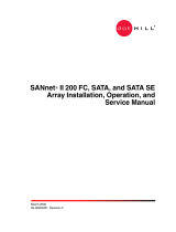
Figure 1 shows an overhead view of the layout of the RAM-SAN system components.

- 6 -
Figure 1 RamSan-210 Layout

- 7 -
2.4 Rack Mounting
The RamSan-210 is a 2U rack-mountable system. The system is shipped with the slides
and equipment needed to install it into a standard 19” rack.
2.5 Connecting the Fibre Channel Ports
After you have inspected the system and properly mounted it, connect the Fibre Channel
ports on the RamSan-210 to either your server or to a Fibre Channel switch. See for a
list of TMS approved SAN hardware.
Figure 2-2 RamSan-210 Interface Plate
Your system will be equipped with either one or two FC32 Fibre Channel controllers.
Figure 2- shows the port layout for the RamSan-210. Each controller has two Fibre
Channel ports A and B, on the left and right respectfully. These port numbers have no
correlation to the port identifiers assigned during port login. They are only used in the
management utilities for identification and LUN assignments. The interface plate also
has a DB-9 RS-232 serial connection and an RJ-45 Ethernet port. These ports are used
for local and remote management of the system. The FC32 ports on the system are
capable of connecting to point-to-point, arbitrated loop, and switched fabric topologies.
2.6 Connecting the Power Supplies
The RamSan-210 is equipped with dual redundant hot-swappable power supplies that
operate on 110/220 VAC line power. Using the provided AC power cords, connect both
power supplies to a source of power.
For normal system operation make sure both power supplies are connected to an external
power source. Since the power supplies are redundant, you may remove line power from
Controller 1 Controller 2

- 8 -
one without any interruption in Fibre Channel service. However, if external power is
completely lost, all Fibre Channel ports will go into a standby mode after a short user-
defined timeout period because the system will power off.
Warning:
Do not remove both power supplies from the system at the same time. This will cause
system failure since the internal batteries require that at least 1 power supply be present
in the system at all times. If both supplies are physically removed from the chassis,
possible data loss may occur.
Figure 2-3 RamSan-210 Power Supply Modules
The following buttons and indicators are on the power supply:
• The top button provides a means to activate the power supplies (turn them on)
after a user-initiated system shutdown. When a user initiates a shutdown of the
system, the power supplies are typically still connected. Therefore, the system
cannot use the presence or absence of AC to know whether to operate. In order
for the power to come on after a user initiated shut down, the top button must be
pressed on either of the power supplies. If power is restored after a power failure
or a power cord is reinserted, the system will automatically power on.
• Low Voltage indicator light. The top indicator light shows when the power
supply is operating below the voltage necessary to power the entire system. Low
voltage indications are a sign that the power supply needs to be monitored and
possibly replaced.
• Battery Operation indicator light. The bottom indicator light shows when the
system is operating from battery power. The system should only operate from
battery power when external AC power has failed.
Warning:
The power supply modules maintain high voltage levels during normal operation. To
prevent the risk of electrical shock, remove the power cord and wait 15 seconds before
removing a power supply module.
Battery
Low Voltage
“On” switch

- 9 -
2.7 Turning on the System
The RamSan-210 will automatically power on when power is connected to the system.
The only time the system will not automatically power on is when a user has initiated a
Manual Shutdown of the system. In the event this has happened, it is necessary to press
the top button on either power supply. Please see 2.6 Connecting the Power Supplies.
2.8 System Initialization
The front panel display shows the current state of the boot process. Once the power is
connected, the system will turn on automatically and the front panel will begin the power
on sequence. The following will happen automatically (this boot sequence can also be
monitored externally through the serial port or Ethernet port):
1. After approximately seven seconds, the RamSan-210 will power-up.
2. You should see “Texas Memory
Systems” appear on the front panel, as
well as “RamSan-210”. Soon after
that you will see “Booting” and
“Initializing RamSan”.
3. After the firmware has finished booting, the front panel display will indicate
“Bringing Disks Online”. The system disks take approximately 10
seconds each to spin-up.
4. The front panel will indicate
“Restoring” and show a progress bar
and give an estimated time till
completion. Administrators may use this
to determine how much time before the
system is on-line. This information is
also available through the telnet remote
monitoring software in the status
command. This process will take
approximately 2 minutes 15 seconds for every 4 gigabytes of memory in the
system.
5. Once the system has restored data, the system will display “Status Good” and
show the performance bars for each Fibre Channel port.
The system is now ready for normal operation.
Please see Chapter 7 – Troubleshooting for possible error conditions during start-up.
Please see Chapter 3 – Using the Front Panel for more information on configuring the
Ethernet and monitoring system health.

- 10 -
Chapter 3 – Using the Front Panel
3.1 Overview
The front panel for the RamSan-210 allows you to inspect the state of the system, change
the method of IP address assignment, and shutdown the system. Four buttons located to
the left of the panel are used to make selections. Figure 4.1 is a picture of the front of the
system.
Figure 3-2 RamSan-210 Front Panel
The buttons on the front panel serve the following functions:
• Menu. The Menu button has two functions:
o Function 1: On any of the status or performance displays, pressing the
“Menu” button will launch the RamSan-210 Main Menu.
o Function 2: Escape function. Pressing “Menu” once the menu is open
returns the user to the prior screen.
• Select. If “Select” is pressed when a menu item is on the screen, the system will
either: execute that menu option or proceed to the next layer in the menu. This
button is disabled if the menu is not selected.
•
↑↑
. The “
↑↑
” button scrolls up through the menu. The “
↑↑
” is also used cancel
certain commands, as indicated on the display. This button is disabled if the
menu is not selected.
•
↓↓
. The “
↓↓
” button scrolls down through the menu. The “
↓↓
” is also used confirm
certain commands, as indicated on the display. This button is disabled if the
menu is not selected.

- 11 -
3.2 Menu System Layout
The front panel menu system is as follows:
RS-210 Main Menu
• Ethernet Setup
§ Set IP Config
§ Static
§ IP
§ Subnet Mask
§ Gateway
§ DHCP
§ BOOTP
§ RARP
§ None
§ No Change (Exit)
§ Restart Network
§ Show Current Config
§ Exit Menu
• Manual Shutdown
§ Power off System?
• Exit Menu
3.3 Ethernet Setup
The RamSan-210 uses both a serial port and an Ethernet port to allow you to monitor and
configure the system. To access the system’s Ethernet port, the RamSan must be
assigned an IP address, subnet mask, and possibly a gateway. The IP address may be
assigned in one of five ways: Static IP, DHCP, BOOTP, RARP, or No Ethernet.
To setup the Ethernet, use the arrow buttons to cycle through the top-level menu options
until “Ethernet Setup” is showing on the display. Use the “Select” button to
choose this option and continue with the configuration. You may now use the arrow
buttons to scroll through the following menu options: “Set IP Config”, “Restart
Network”, “Show Current Config”, and “Exit Menu”. “Restart
Network” will shutdown and restart the Ethernet port using the current IP assignment
configuration. Selecting “Show Current Config” will display a list of the current
IP configuration, hostname, IP address, subnet mask, gateway address (if applicable), and
hardware Ethernet address. Use the arrow buttons to scroll up and down through the list.
Pressing the “Menu” button will return to the previous menu, and pressing the “Select”
button will exit the menu system. To continue setting up the Ethernet configuration,
select “Set IP Config”.

- 12 -
After selecting “Set IP Config”, you may use the arrow buttons to cycle though
“Static IP”, “DHCP”, “BOOTP”, “RARP”, “None”, and “No Change”. Talk to
your system administrator for the proper IP assignment type. Use the “Select” button to
select the desired method of IP assignment. If you did not choose “Static IP” you
are asked to confirm the selection with the “
↓↓
” button.
If you are setting up the RamSan-210 with a static IP, you need to have the Ethernet IP,
subnet mask, and a gateway address if you need to access the device from a different
network. After you have chosen “Static IP”, “Ethernet IP” replaces the top line
of the display, and you will be prompted to enter an IP. The “
↑↑
” or “
↓↓
” buttons cycle
through the numbers “0” through “9”. To select the value, use the “Select” button. The
input prompt will move to the next character position. To back up a space, press the “
↑↑
”
and “
↓↓
” button simultaneously. You can press the “Menu” button at any time to cancel
the Static IP assignment. Repeat this procedure until the 4-byte address has been entered.
After you have finished entering the IP, the top line of the front panel will change to
“Subnet Mask”. Using the same procedure as entering the IP address, enter the subnet
mask. The final value you must enter is the “Gateway Address”. If the RamSan-210
is on a private network and this value is not needed, enter the value “0.0.0.0” to tell
the RamSan-210 to ignore this entry. After entering all three values, you will be
prompted to confirm the command with the “
↓↓
” button.
After confirming the new IP assignment mode, the display will indicate “Shutting
Down Network…” followed by a success or failure message. The display will then
indicate “Saving IP Config…” followed by a success or failure message. Next, the
RamSan-210 will attempt to start the network with the new settings, indicated on the
front panel display with “Restarting Network…”. Upon success, the new IP
address is displayed on the front panel for 15 seconds or until any button is pressed. If
the network fails to start, check the Ethernet connection and contact your system
administrator. If the IP configuration was successfully saved, you may simply select the
“Restart Network” option from the “Ethernet Setup” menu instead of re-
selecting the same IP configuration.
For any questions regarding IP assignment values, please consult with your network
administrator.
3.4 Manual Shutdown
The RamSan-210 may be shut down from the front panel. This procedure will safely
synchronize all data in RAM to the internal disk drive storage.
To shut down the system using the front panel, use the arrow buttons to cycle through the
top-level menu to select “Manual Shutdown”. Use the “Select” button to select this
menu item. You will be prompted to confirm that you wish to “Power Off System”.
To cancel the shutdown, use the “
↑↑
” button again to return to the main menu. To proceed
with the shutdown, use the “
↓↓
” button to confirm the system power off. The front panel

- 13 -
display will now indicate that the system is powering off. This will typically take
between 5 and 15 seconds to complete.
As a reminder, in order to turn the RamSan-210 back on after a manual shutdown it is
necessary to press the top button on either power supply.
3.5 System Monitoring
When the menu on the front panel is not in use, it is possible to monitor various aspects
of the system. The following information is presented:
• Fibre Channel port bandwidth. The front panel displays the Read and Write
performance of each Fibre Channel port. As seen in the picture, the indicator
lights correspond to the actual location of the ports on the RamSan-210. The top
indicators are for the top Fibre Channel interface board. The bottom indicators
are for the bottom Fibre Channel interface board. The left and right indicators
map to the left and right sides of the interface boards when you look at them from
behind. For each channel, the top half of the graph represents read megabytes per
second in 10 megabyte per second increments. The bottom half represents write
bandwidth.
• Restore/Backup Progress. During any backup or restore, the front panel will
display the operation progress and estimated time remaining until completion.
• Status. The following status levels are possible:
o “Good”. This is normal
operation.
o “*WARN*”. This indicates that a
System Warning has been
detected. Possible warnings
include:
– Front or rear fan trays
removed
– Power supply removed
– AC Lost at one or both
power supplies
– One or both batteries have been removed
– Temperature warning
– One or both disks removed

- 14 -
o “*FAIL*”. This indicated that a System Failure has been detected.
Possible failures include:
– Front or rear fan trays have a failed fan
– Power supply failed
– One or both batteries have failed
– System overheated
– One or both disks have failed
In the case of either System Warnings or Failures, the front panel display will
alternate between displaying status information and Warning/Failure messages
every 10 seconds.

- 15 -
Chapter 4 The Management Control Port (MCP)
4.1 Connecting to the MCP
The management port on the RamSan-210 allows you to manage, configure, and monitor
system behavior. This includes obtaining status information about internal hardware,
configuring the LUNs, and obtaining data rates of the system.
You may connect to the management port using either a DB-9 serial cable or an RJ-45
Ethernet cable.
4.1.1 RS232 Serial Port
To connect to the serial port use the DB-9 non-null serial cable supplied with the
system. You need to set your terminal program to 9600 baud, 8 data bits, no
parity, and 1 stop bit.
4.1.2 Ethernet
In order to use the Ethernet port, you must first configure the IP address for the
RAM-SAN. You may configure the IP using the front panel display or from the
serial port. For a complete description for configuring the Ethernet using the front
panel, please refer to Section 3.3 of this manual. If you are configuring the
Ethernet using the serial port refer to Section 4.5.5 of this manual.
4.2 Connecting using a terminal program
To connect to the RamSan-210 using a serial port connection, you must use a dumb
terminal or a terminal emulation program such as Windows™ HyperTerminal. Your
baud rate should be set to 9600 with 8 data bits, 1 stop bit, no parity, and no flow control.
4.3 Connecting using telnet
Once the Ethernet port on the RamSan-210 has been configured using either the front
panel or the serial port, you may remotely monitor the system using a telnet session.
Your terminal settings should be set to VT100 mode.
4.4 Logging into the system
The RamSan-210 has two login accounts, “root” and “user”. Default passwords for both
accounts have been left blank.
/