Page is loading ...

Access Control Power Distribution Board
ENFORCER
®
Installation Manual
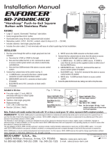
Installation:
1. Mount the PC board in the desired location or enclosure. It must be
easily accessible for future sevicing.
2. Connect the output wires of the 12VDC or 24VDC power supply to
the PC board's terminals marked "DC INPUT" as required, see Fig.8.
NOTE: Correct polarity must be observed.
3. Connect the power input wires of the access control devices or
accessories to the PC board, see Fig.8. Observe correct polarity. For
fail-secure devices, connect positive to terminals marked "POS.
OPEN LOOP" and negative to terminals marked "NEG."
For fail-safe devices, connect positive to terminals marked "POS.
CLOSE LOOP" and negative to terminals marked "NEG".
NOTE: For best results and to minimize voltage drop, these wires
should be a minimum of 18-gauge in thickness.
4. Connect a visual or audio indicator device (such as siren or strobe
light) to the "POWER FAIL" supervision relay and "Auxiliary output"
relay if needed, see Fig.8. Use between 22AWG to 18AWG wire size.
5. Trigger the power distribution board either from a wet and or dry
contact switch from the control station by following the connection
diagrams shown on Fig. 2~7. See Table 1 on how trigger input
function works.
IMPORTANT NOTE: If the "TRIGGER" terminal block
function will not be used, then a 2.2K
ΩΩ
ΩΩ
Ω resistor must
always be connected to the "TRIGGER" terminal block as
shown in Fig. 1.
PD-5PAQ
Features:
•
Five individually PTC-fused outputs
•
Each output will operate in both fail-safe and fail secure modes
•
Output fuses rated 1.1 Amps
•
Individual LED status indicator for each output,
power input, and trigger.
•
For 12VDC or 24VDC operation.
•
Power failure supervision relay (3 Amps @ 24VDC)
•
Auxiliary supervision relay (3 Amps @ 24VDC)
•
Equipped with dry and wet trigger inputs.
•
Dimensions - 3
9
/
16
” x 5
5
/
16
" x 1
1
/
16
" (90 x 135 x 27 mm)
Note: Products with model numbers that end with "Q" or that have a round green “Q” sticker are RoHS compliant.
Compatible with the following ENFORCER power supplies
EAP-5D1MQ – 5 Amp Access Control Power Supply/Charger Module
EAP-5D1Q – 5 Amp Access Control Power Supply with metal enclosure
Fig. 2 – Momentary trigger wiring diagram for wet and / or dry N.C. switch.
DC voltage input from control station
N.C.
switch
Fig. 1 – Wiring diagram when "Trigger" terminal will not going to be used.
2.2KΩ resistor(supplied)
Fig. 3 – Momentary trigger wiring diagram for wet and / or dry N.O. switch.
N.O.
switch
DC voltage input from control station
2.2KΩ
resistor
(supplied)
2.2KΩ resistor(supplied)
What it is:
This 5-output power distribution board centralizes the power sources for access control electronic locking devices, such as
electromagnetic locks, sheer locks, electric door strikes, deadbolt locks, and so on. It provides a separate fuse for each output so that
problems with one device may be isolated from the other devices. Each output operates in both fail-safe and fail-secure modes. The
board includes wet and dry trigger inputs for emergency door activation such as for releasing emergency exit doors. It is also equipped
with power failure supervision relays and auxiliary supervision relays.

2.2KΩ
resistor (supplied)
N.0. switch from access
control panel
N.C. switch
for RESET
Fig. 4 – Latch trigger wiring diagram for wet and / or dry N.O. switch
2.2KΩ
resistor (supplied)
N.O. switch
for RESET
Fig. 5 – Latch trigger wiring diagram for wet and / or dry N.C. switch
N.C. switch from access
control panel
Fig. 8 – Wiring diagram.
WARRANTY:
This SECO-LARM product is warranted against defects in material and workmanship while used in normal service for a period of one (1) year from
the date of sale to the original consumer customer. SECO-LARM’s obligation is limited to the repair or replacement of any defective part if the unit is returned, transportation
prepaid, to SECO-LARM. This Warranty is void if damage is caused by or attributed to acts of God, physical or electrical misuse or abuse, neglect, repair, or alteration,
improper or abnormal usage, or faulty installation, or if for any other reason
SECO-LARM determines that such equipment is not operating properly as a result of causes other than defects in material and workmanship. The sole obligation of
SECO-LARM, and the purchaser’s exclusive remedy, shall be limited to replacement or repair only, at SECO-LARM’s option. In no event shall SECO-LARM be liable for
any special, collateral, incidental, or consequential personal or property damages of any kind to the purchaser or anyone else.
NOTICE:
The information and specifications printed in this manual are current at the time of publication. However, the SECO-LARM policy is one of continual
development and improvement. For this reason, SECO-LARM reserves the right to change specifications without notice. SECO-LARM is also not responsible for misprints
or typographical errors.
Copyright © 2011 SECO-LARM U.S.A., Inc. All rights reserved. This material may not be reproduced or copied, in whole or in part, without the written permission of SECO-LARM.
SECO-LARM
U.S.A., Inc.
,,
,,
, 16842 Millikan Avenue, Irvine, CA 92606
Tel: 800-662-0800 / 949-261-2999 Fax: 949-261-7326
Website: www.seco-larm.com
E-mail: sales
@
seco-larm.com
MiPD-5PAQZZ_1107.pmd
Order Part #764-019-1%
PITSW1
Used to notify loss of DC power. To connect a visual or audio warning device
(such as siren or strobe light). Dry contact relay rated at 3 Amps @ 24VDC
If VDC input to the PDM is interrupted, the connected warning device will be activated.
Used to connect wet (5-30VDC) input trigger signal from access control
panel. Applying Voltage will transfer power from "POS. CLOSE LOOP"
to "POS. OPEN LOOP.
Terminal Legend
TRIGGER
Used to activate other auxiliary device when trigger signal is received from
the "TRIGGER" or "VOL TRIGGER" terminals.
Used to connect N.O. or N.C. input trigger sinal (supervised 2.2KΩ resisitor)
from access control panel. A short or open circuit will transfer power from
"POS. CLOSE LOOP" to "POS. OPEN LOOP.
VOL. TRIGGER
POWER FAIL
AUX OUTPUT
- DC INPUT +
12 or 24 VDC input from main board.
Table 1 – Terminal Function
Functions
Output 2:
Fail-Safe
Magnetic Lock
Output 1:
Fail-Secure
Door Strike
DC voltage input signal from
Access Control Station
or emergency switch
12 or 24VDC input
Auxiliary Output Relay for
other system integration
DC Power Fail Supervision
Relay for Audio / Visual
warning device
Fig. 6 – Multiple PD-5PAQ momentary trigger wiring diagram for wet and / or
dry N.O. switch.
For Additional
PDM if needed
DC voltage
input from
control station
2.2KΩ
resistor (supplied)
N.O.
switch
First
power
distribution
board
Fig. 7 – Multiple PD-5PAQ momentary trigger wiring diagram for wet and / or
dry N.C. switch.
For Additional
PDM if needed
N.C.
switch
2.2KΩ
resistor
(supplied)
DC voltage
input from
control station
2.2KΩ
resistor
(supplied)
NO trigger input
from Access Control
Station or emergency
switch
or
NC Trigger input
Second
power
distribution
board
Second
power
distribution
board
First
power
distribution
board
/


