
SD-997B-1SQ
Mini Surface-Mount Deadbolt
• Fail-safe operation (unlocks if power is lost).
• Surface-mount design for easy installation.
• Magnetic switch senses door position for positive locking.
• Aluminum alloy bolt,
15
/32”(12.7mm) diameter,
9
/16”(14mm) throw.
• Automatically relocks after 6 seconds if the lock was unlocked but the door was
not opened.
• Door open/close monitor (NC/COM).
• Lock delay timer adjustable between 0 and 3 seconds.
• Use with an optional digital keypad for high security without a key.
• Powered by a solenoid.
Manual
SECO-LARM
®
Electric Deadbolt
Electric Shear Lock
SD-993B-SS
Holding force:
1,500lb(680kg).
Small size for use with
most metal door jambs.
Available with 80, 300,
600, 1,200, or 1,300-lb
holding force. All locks
come with a lifetime
warranty.
Electromagnetic Locks
SD-997B-GBQ
Fail-safe,
12/24 VDC operation.
With door-position
monitoring output.
Universal Door Strike
SD-996C-NUQ
Field selectable fail-safe or
fail-secure operation.
UL listed.
Mini Surface-Mount Deadbolt Manual
4
SECO-LARM U.S.A., Inc.
PITSW2
MiSD997B-1SQ_1401.pmd
SECO-LARM
®
U.S.A., Inc.U.S.A., Inc.
U.S.A., Inc.U.S.A., Inc.
U.S.A., Inc.
16842 Millikan Avenue, Irvine, CA 92606
Tel: 800-662-0800 / 949-261-2999 Fax: 949-261-7326
Website: www.seco-larm.com
E-mail: sales
@
seco-larm.com
WARRANTY: This SECO-LARM product is warranted against defects in material and workmanship while used in normal service
for a period of one (1) year from the date of sale to the original consumer customer. SECO-LARM’s obligation is limited to the repair
or replacement of any defective part if the unit is returned, transportation prepaid, to SECO-LARM.
This Warranty is void if damage is caused by or attributed to acts of God, physical or electrical misuse or abuse, neglect, repair, or
alteration, improper or abnormal usage, or faulty installation, or if for any other reason SECO-LARM determines that such equipment
is not operating properly as a result of causes other than defects in material and workmanship.
The sole obligation of SECO-LARM, and the purchaser’s exclusive remedy, shall be limited to replacement or repair only, at SECO-LARM’s
option. In no event shall SECO-LARM be liable for any special, collateral, incidental, or consequential personal or property damages of any
kind to the purchaser or anyone else.
NOTICE: The information and specifications printed in this manual are current at the time of publication. However, the
SECO-LARM policy is one of continual development and improvement. For this reason, SECO-LARM reserves the right to change
specifications without notice. SECO-LARM is also not responsible for misprints or typographical errors.
Copyright © 2014 SECO-LARM U.S.A., Inc. All rights reserved. This material may not be reproduced or copied, in whole or in
part, without the written permission of SECO-LARM.
Possible cause:
Troubleshooting:
Also Available from SECO-LARM:
Deadbolt does not activate
when the door closes.
Deadbolt activates when
the door is closed, but does
not lock the door.
How to reset unit.
For any other problems
Problem:
The sensor in the lock body
is too far from the magnet
in the strike plate.
Deadbolt may not be
properly going into the
deadbolt hole in the door.
• Try adjusting the strike plate, lock body position, or shims.
• Ground the green wire momentarily.
• Make sure the deadbolt is going into the hole and not hitting
the strike plate. If not, you must reposition the strike plate.
• If the deadbolt is going into the hole, it may be hitting the bottom of
the hole (if it is in a wooden door). In this case, drill a deeper hole.
• Substitute a problem unit for a working unit in another door frame to
see if it works there.
Solutions:

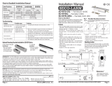
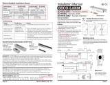
Installation:
1. Determine where the deadbolt will be mounted (see fig. 1).
2. Adjust the wire output direction based on the selected application and adjust the lock delay time if
necessary (see fig. 3).
Adjust the wire output direction
a. Unscrew the 2 screws and remove the cover of the lock body.
b. Remove the wire grommet from the lock body and insert the wires of the 5-pin connector into the
grommet .
c. Plug the 5-pin male connector into the 5-pin socket and adjust the desired wire output direction as
shown in fig. 3.
Adjust lock delay time
a. The default lock delay time is 3s. To remove the delay time, remove the jumper (see fig. 3).
3. Use the screw holes of the lock body and strike body as template and mark the locations of the screws
with a pencil.
4. Secure the lock body and strike body with the 6 included screws. Use 4 screws for the lock body and 2
screws for the strike body. Cover the screw heads with the provided screw cover stickers.
Note: If there’s a gap betweent the lock body and the strike body, use the included 2 plate spacers to correct
the alignment as shown in fig. 2.
5. Connect the wires and insulate them (see fig. 4):
a. Red – Power input (+)
b. Brown – Power input (-)
c. Green – Control wire (-) ground to release bolt
d. Blue – Door monitor, COM
e. Purple – Door monitor, N.C. (active when door closed)
Warning :
1. Correct polarity of the red and brown wires is critical. Incorrect polarity will burn out the solenoid .
2. Do not connect a voltage input on the green wire otherwise it will damage the unit.
3. Maximum distance between lock body and strike body must not exceed 6mm.
32
Mini Surface-Mount Deadbolt Manual
SECO-LARM U.S.A., Inc. SECO-LARM U.S.A., Inc.
Introduction:
The SECO-LARM Mini Surface-Mount Electric Deadbolts is designed for hollow metal door frames and solid
wooden door frames. Its small size makes it easy to add secure, electrical locking to small doors.
Specifications:
Fig. 1 – Possible Mounting Locations.
Fig. 4 –Wiring Diagram
Fig. 2 – Using the Plate Spacers
Card reader
or keypad
COM
N.C.
N.O.
Request-to-Exit
pushbutton
Purple wire (Door Monitor, N.C.) – active if door is locked
Blue wire (Door Monitor, COM) – manual lock/unlock
Red wire (+)
Brown wire (
-
)
Green wire (Control wire)
12VDC
Power
Supply
Fig. 3 – Adjusting the Lock Delay Time / Wire Output Direction.
Adjust wire grommet for
different wire output direction
Lock delay jumper
5-Pin Connector
5-Pin Socket
Jumper
ON
Plate spacer
Vertical mount
Horizontal mount
Strike body
Lock body
Mini Surface-Mount Deadbolt Manual
Delay Time
3s (default)
0s
OFF
1x Lock body
1x Strike body
2x Plate spacer
Parts List: 1x 5-pin connector
6x Mounting screws (M4x40mm)
6x Screw cover stickers
Lock body Strike body
Plate spacer
Overview:
Operation
Operation voltage
Current draw
Status sensor
Adjustable lock delay timer
Operating Temperature
Weight
Standby
Active
250mA@30VDC (NC/COM)
Fail-safe
12VDC
237mA@12VDC max.
650mA@12VDC max.
0/3 s (default)
32°~158° F (0°~70° C)
1-lb,2.5-oz (450g)
-
 1
1
-
 2
2


Ask a question and I''ll find the answer in the document
Finding information in a document is now easier with AI
Related papers
-
SECO-LARM SD-997B-GBQ Owner's manual
-
SECO-LARM SD-969-M15Q/S Owner's manual
-
-
SECO-LARM SM-217Q/W Miniature Surface Mount Wide Gap Magnetic Contacts User manual
-
-
-
-
-
-
SECO-LARM E-941DA-600Q Owner's manual
Other documents
-
SkyLink ES-201 Installation guide
-
 ENFORCER SD-997A-DQ Installation guide
-
 ENFORCER SD-997A-GBQ Installation guide
-
ENFORCER SD-7202GC-PTQ Installation guide
-
 ENFORCER SD-997SMB-AQ Installation guide
-
 Lock Control SL-133 Installation guide
-
 ENFORCER SK-2611-SFSQ Installation guide
-
 ENFORCER CS-PD115-PAQ Installation guide
-
ENFORCER SD-927PKC-NFQ User manual
-
 ENFORCER DP-236Q Installation guide


