Page is loading ...

Standard Sectional
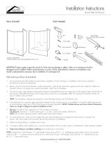
Installation Instructions
1. Do NOT store units out of doors. Keep out of sunlight
and exposure to weather.
1. Remove wall section(s) from the base unit. Carefully
move all parts into the installation area. Apply a bead
of 100% Silicone Caulk to all joints. Re-install the wall
sections. Align all parts by making sure the wall
sections using the factory provided alignment pins
and slots. Units have one or more alignment pins
with corresponding slots that help to assure the parts
line up correctly. Once the 100% Silicone Caulk is
applied and the parts re-assembled, wipe away any
excess caulk that squeezes out. The unit will be
installed into the framing alcove as a one piece unit.
The unit must be installed completely level.
Alternate Connection: If installing piece-by-piece into
the alcove, make sure the pins and slots are aligned
correctly. When the 100% silicone Caulking is cures the
parts are solidly held similar to a one piece unit when
secured to the framing.
See Photo 1.
The valve wall should be the last wall to be installed.
Tools and materials you might need for proper installation:
6D Galvanized Screws
Tape Measure
Caulking Gun
Philips Screw Driver
Long Level
Bathroom Caulk - (see page 3, step 8)
100% Silicone Caulk
1/8” Drill Bit
PRE-INSTALLATION PLANNING
INSTALLATION PROCEDURE
Thank you for purchasing Laurel Mountain Bathware.
For best results, please read and follow all directions carefully.
READ INSTRUCTIONS COMPLETELY
BEFORE BEGINNING INSTALLATION.
3. Review Figures 7 and 8 to make sure alcove is of proper size.
If a fire rated alcove is required, approved finish
material must be installed prior to unit installation. Access to
drain and supply connections should be provided so that
these connections may be made after the unit has been
installed. Framing alcove must reflect dimensions on diagrams
to permit unit installation. Note in diagrams the required
opening in the floor to provide clearance for the drain fitting
and connection.
4. These units are trimmed to be self-leveling at the factory.
If the sub-floor at the installation site is not perfectly level, it will
be MANDATORY to provide shims under the back edge of the
unit to level the unit.
See Figure 1 if shimming is required.
2. The drain and/or oveflow assembly should be installed
on the unit according to the manufacturers instructions.
Apply a bead of 100% Silicone Caulk around the drain
hole opening in the unit before installing the fitting.
3. Locate supply lines for control valves and shower head.
Measure and mark locations of fittings on the finished
side of the unit. Re-check locations and drill 1/4” pilot
holes. Cut holes to final size using the appropriate
size hole saw.
4. Carefully carry the unit to the installation location and
trial fit into the framing alcove. Check for level along
the front of the side walls and on top of the apron/dam.
If unit is not level, shims will need to be located on the
sub-floor to support the back edge of the unit.
Remove the unit and secure the shims as required to
make the unit level when installed. Remove and
adjust shims if required to assure level and proper
support. Secure shims so they will not move.
s out of doors.- Keep
out of sunlight and exposure to weather.
make
fire rated
material must
Access to
provided
fter the
alcove must
permit
required
for the
(provided)
structural
support of the base unit. See Figure 1.
base
NAL GELCOAT BATHING SYSTEMS
W
(If Necessay To Level Unit)
ood Support Shims
Two wood shims are provided in the installation
It is MANDATORY that these wedges are in place
and in proper contact to assure structural integrity
of the bathing unit.
Figure 1
Photo 1
-1-
2. Do not remove the Medallion Identification number,
doing so may affect the warranty. This number may be
found above the drain, left or right corner of the unit.

Standard Sectional
Installation Instructions
5. Plumb and level the unit in two directions: Place a level
on top of the apron and along the finished flat area of
the top of all walls. Once the unit is leveled, if any gap
appears between the apron and sub-floor, fill this gap
with solid material. When satisfied with the fit, pre-drill
1/4” holes through all mounting flanges 8” O.C. vertical
and at each stud horizontally. Attach the unit to the
framing with 6D galvanized screws.
6. Make connections to supply and drain lines. Strap all
lines to the framing. Install finished trim. Caulk along all
fittings as necessary.
1. Install drain and/or overflow assembly on the unit
following drain manufactures instructions. If required,
place shims under the back edge and secure. Place
the base unit in the alcove location. Level the base.
Check for level and plumb in two directions.
When level, secure to framing using galvanized screws.
2. Place a continuous bead of 100% silicone calulk along
the top flat surface of the base where the wall sections
will sit. Make sure caulk surrounds all guide pins.
For three and four piece units, apply silicone up the
vertical seams where the parts will meet.
3. Place the walls on top of the base, aligning the slots
with the pins. For three piece units, install the valve wall
last. Repeat the same for the opposite wall.
Make sure the parts are seated in the silicone, and that
all seams are even and in alignment. Press all seams
together to assure a tight fit. Wipe away any excess
caulk before it cures. See Figure 5.
4. For four piece units, install the back wall first. Install the
left and right walls (valve wall last). Press the seams
together to assure a tight fit. Make sure all seams are
in alignment. Wipe away any excess caulk before it
cures.
5. Re-check to make sure all seams are even and in
alignment with the base section. Fasten the walls to
the framing using 6D galvanized screws through the
mounting flanges. Fasten every 8” O.C. along the
vertical flanges and into each framing stud along the
top horizontally.
6. Make connections to supply and drain lines. Strap all
lines to the framing. Install finished trim.
Caulk if necessary.
7. Check for leaks before installing wall board and closing
off plumbing access. NOTE: Laurel Mountain is not
responsible for leaking connections.
7. Check for leaks before installing wall-board and closing
off access to the plumbing.
8. Finish wall board as detailed in Figure 2.
Sectional bathing units are shipped from the factory with
screws or nuts and bolts connecting the parts together.
If installing the unit fastened together as one piece, follow
instructions on Page 1 of this manual.
The alignment pins should allow you to more easily install
the unit in the framing alcove. Read and understand the
instructions on this page since the alignment pins must be
inserted in a specific direction.
Note: If using shims it is MANDATORY these shims are in
place and in proper contact to assure structural integrity
of the bathing unit.
-2-
Figure 3
5 .
6.
7.
8.
Plumb and level the unit in two directions:
Place a level on top of the apron, and along the
finished flat area at the top of the wall. Once the unit
is leveled, if any gap appears between the apron and
sub floor fill the gap with solid material. When satisfied
with the fit, attach the unit to framing with 6d galvanized
nails or screws through the predrilled holes in the
mounting flanges. If required, drill additional holes
through the flanges in order to attach the unit to each
stud.
Make connections to supply and drain
lines. Strap all lines to the framing. Install finish
trim. Caulk as necessary.
Check for leaks before installing wall-board and
closing off plumbing access.
Finish wall
board as
detailed in
the diagram.
Shim Along
Framing
Wall
Board
M o u n t i n g
Flange
Caulk
Gap
Framing
Wood Support Shims
Two wood shims are provided in the installation
packet attached to the unit. Additonal shims may be
added by the installer.
It is MANDATORY that these wedges are in place
and in proper contact to assure structural integrity
of the bathing unit.
Figure 2
Figure 1
SIDE VIEW
INTEGRAL SELF-LOCATING
GUIDE PIN DETAIL
INTEGRAL SELF-LOCATING
GUIDE PIN ON BASE
Note: Number and
location of pins may vary.
CAULKING DETAIL
Apply along the at where
walls will sit.
Apply around all pins.
PIN

Standard Sectional
Installation Instructions
-3-
Install drain and/or overflow assembly on unit
following drain manufacturers instructions.
Place support wedges under the back edge and secure
Place the base unit in the install location. Level the unit.
with adhesive. A minimum of two shims should be used
for proper support. (See Figure 5). Re-check level and
attach base to framing studs with 6D galvanized screws.
6.
Fiberglass Unit
silicone should make
act with bottom ledge of the base.
Silicone Bead
Plastic Fastener
er applying the
c fasteners for the
through the holes
(the wall to the left
acing the right and
firmly to the backside
he silicone to the
walls, insert them
the back wall. These
backside and pressed
fasteners fully contact the
pointing out towards
7.
Support Wedges
(Secure with adhesive)
Place a continuous bead of silicone on
base between the edge of the base and the holes
(As shown in Figure 4B). For three and four piece
units,apply silicone up the veritical seam(s) between
the holes for the fasteners and the front or inside edge
of the wall.
Figure 3
Figure 4B
Place the walls on top of the wooden blocks. One
by one remove the blocks taking care to align the
plastic fasteners into the holes in the underside of the
walls. For three piece units, install the left wall first.
Repeat for the right wall. Press all seams together to
8.
For four piece units, install the back wall first. Install
the left and right walls, (Wet wall last.) Take care to
align the plastic fasteners into the holes in the walls.
Press the seams together, to assure a tight fit.
Wipe away any excess caulking before it cures.
assure a tight fit. wipe away any excess caulking.
See Figure 5.
2
Figure 5
9.
10.
11.
12.
G 3838.51
Model No.
6824/25
6839
Fig 5 Fig 7 Fig 6 ABCDEFGHIJ
N/A N/A 27”
79”
73”
74”
74”
74”
73”
73”
73”
39-1/2”
60-1/4”
32-1/4”
36-1/4”
48-1/4”
36-1/4”
48-1/4”
60-1/4”
39-1/2”
31-7/8”
33-1/2”
36-1/2”
37-5/8”
35-5/8”
31-1/4”
17-3/4”
14-3/4”
16-1/2”
18”
18”
16-1/8”
16-3/8”
14-1/2”
17-3/4” 17-3/4”
2-5/8”
16”
18”
24”
18”
24”
1-3/8”
14-3/4”
16-1/2”
18”
18”
16-1/8”
16-3/8”
14-1/2”
75”
76”
76”
76”
83-3/4”
83-3/4”
83-1/8” 83-1/8”
83-3/4”
83-3/4”
82”
82”
82”
81”
48”
19”
48”
48”
48”
48”
48”
17-1/2”
42-1/4”
22”
22”
22”
22”
22”
43”
X
X
X
X
X
X
X
X
36-1/2”
Old No.
G 3838 NA 2P
G 6032 TS 2P
G 3232 SH 2P
G 3635 SH 2P
G 4836 SH 2P 1S
G 3636.53
G 6030.75
G 6036.71 6976/77 X76” 60-1/4” 35-3/4” 15” 2” 15” 79” 82” 25-1/4” 38-1/4”
G 6036.72 6880/81 X81” 60-1/4” 37” 17-1/2” 1-5/8” 17-1/2” 81-1/4” 81-1/4” 22” 42-1/2”
G 6030.74
G 3232.50
G 3635.53
G 4835.54
G 4834.50
G 4834 3P 2S
G 3260 TS 3P N/A
G 5494 TS 2P N/A
G 4887 SH 3P 1S N/A
X
X
X
60-1/4”
74” 32-3/4” 16” N/A 16” N/A N/A N/A
N/A N/A N/A
N/AN/AN/A
74” 54-1/4” 27-1/2” 12-1/4” N/A 12-1/4”
N/A
N/A
N/A
78” 48-1/4” 35-3/4” 18-1/4” 24” 18-1/4”
FRAMING DIMENSIONS
Do not use abrasive cleaners
If you use a RUBBER FLOOR MAT in this
tub or shower unit it must be removed after each
usage. If left in the unit, it may cause blisters or
damage to the surface finish.
G 6017 TS 2P N/A X81” 60-1/4” 37-3/4” 16” N/A 16” N/A N/A N/A N/A
G 4887 SH 2P 1S N/A X78” 48-1/4” 35-3/4” 18-1/4”18-1/4” 24” 18-1/4” N/A N/A N/A N/A
G 3679 SH 3P N/A X78” 36-1/4” 37” 19” 18” 19” N/A N/A N/A N/A
G 3687 SH 2P X
N/A 79” 36-1/4” 36-1/4” 17-1/2” 18” 17-1/2” N/A N/A N/A N/A
G 3275 SH 2P X
N/A 77” 32” 34” 19-1/2” 16” 19-1/2” N/A N/A N/A N/A
Praxis Companies LLC.
435 Industrial Road
Savannah, TN. 38372
Phone: (800) 443-7269
Fax: (731) 925-7656
Make sure all seams are even and in alignment
with the base section. Fasten the wall assembly
to the framing using 6D galvanized screws through the
mounting flanges. Fasten every 8” O.C. along the vertical
flanges and to each framing stud along the top, horizontally.
The most important caution is to avoid use of harsh
abrasive cleaners or gritty scouring powders. To clean
the unit, simply use a household liquid detergent with
soft sponge cloth and warm water. More persistent
stains, tar, or paint can be removed with naptha or
mineral spirits.
Remove excess plaster by scraping with a sharpened
soft wood stick. Avoid wire brushes, metal scrapers
or tools. Restore dull areas by rubbing with automotive
type body cleaning compound.
CAUTION:
Make connections to supply and drain
lines. Strap all lines to the framing. Install finish
trim. Caulk as necessary.
Check for leaks before installing wall-board and
closing off plumbing access.
Finish wall
board as
detailed in
the diagram.
Shim Along
Framing
Wall
Board
M o u n t i n g
Flange
Caulk
Gap
Framing
Figure 6
NOTE: Use wedges only if required
If you use a RUBBER FLOOR MAT in the tub or shower
unit it must be removed after each usage. If left in the unit,
it may cause blisters or damage to the surface finish.
The most important caution is to avoid the use of harsh
abrasive cleaners or gritty scouring powders. To clean the
unit, simply use a household liquid detergent with a soft
sponge or cloth with warm water.
More pesistent stains, tar or paint can be removed with
naptha or mineral spirits. Remove dried plaster by
scraping with a soft sharpened wooden stick. Avoid wire
brushes, metal scrapers or tools. Restore dull areas by
rubbing with automotive type body cleaning compound.
Laurel Mountain warrants to the origional purchaser to be free from defects in material and workmanship for the folowing
periods. The bathing unit shell carries a limited lifetime warranty. The grab bars, drain and curtain rod have a limited 10 year
warranty. All other parts have a limited 5 year warranty. Proof of purchase is required. This warranty is issued to the origional
purchaser and shall be effective from the date of purchase as shown on purchasers receipt.
Laurel Moutain will repair or replace (at their choice) any unit which proves to be defective in material or workmanship under
normal use and service, having been properly installed. This warranty is the only express warranty made by Laurel Mountain
and is limited to the duration of this warranty. Any labor charges and/or damage incurred in installation, repair or
replacement as well as incidental and consequential damages connected therewith are excluded and will not be paid by
Laurel Mountain. Some states do not allow the exclusion or limitation of incidental or consequential damage, so the above
limitation or exclusion may not apply to you. This warranty is void for any damages to the unit due to abuse, misuse,
neglect, accident, improper installation, any use violating instructions furnished by us, or repair not authorized in writing by
Laurel Mountain.
2021, Laurel Mountain
Laurel Mountain
26 Nesbitt Road, Suite 257
New Castle, Pa 16105
Customer Service 800-930-0050 [email protected]
CAUTION
DO NOT USE ABRASIVE CLEANERS
LIMITED WARRANTY
c
8. Apply bathroom caulk to all seams. Wet your finger and
run along the caulk to produce a consistent, smooth
bead in the seam.
9. Finish wall board as detailed in Figure 6.
To valadate your warranty, record your order date,
PO # and Serial # and store in a safe place
The order date & (8-digit) PO # can be found on your Lowes receipt.
The serial # is located on your unit (see example to the right).
Order Date:
PO #:
Serial #:

Standard Sectional
Installation Instructions
-4-
2021_ LM_Standard Sectional Installation Guide REV 5-20-2021-JH
25.00$
$ 25.00
Sectional Tub/Showers Sectional Showers
Praxis Companies warrants to the owner of its Tub/Shower units as follows:
Units manufactured of fiberglass reinforced polyester resin, that it will, free of charge, repair or exchange as its option, any Praxis Companies unit found to be defective
in materials or workmanship upon inspection by an authorized representitive of Praxis Companies for a period of three (3) years from date of purchase. The exchange
of a unit is limited to supplying a replacement unit of comparable size and style and does not include any costs of removal or installation.
This warranty shall be voided if the unit is moved from its place of initial installation or is not installed in accordance with the instructions supplied by the manufacturer
of the unit. Further, this warranty does not apply if the unit has been subjected to accident, abuse, misuse, damage caused by flood, fire or act of God.
Since local code requirements vary greatly throughout the country, distributers, dealers, installation contractors and users of plumbing products should determine whether
there are any code restrictions on the use of a specific product. Praxis Companies makes no representation or warranty regarding and shall not be responsible for
any code compliance.
The owner agrees by use of this unit that the obligations of Praxis Companies shall not exceed to contingent or indirect damage or injury to the structure of its contents,
that the obligations of Praxis Companies are limited to those set forth herin, and that no other obligations, expressed or implied, are assumed by Praxis Companies.
LIMITED WARRANTY
D
L
C
OUTLET
C
B
E
/2”
1
8
L
C
Fittings
L
C
A
G
J
I
Shower
H
Blocking
(optional)
Shower Head
and Fittings
L
C
F
Header for
Optional
Dome
Shower Head
and Fittings
L
C
Header for
Optional Dome F
H
G
J
Shower
L
C
Blocking
(optional)
A
I
Fittings
L
C
E
B
D
C
Outlet
C
L
Spout
Figure 7 Figure 8
13”
13”
/