MAAX 106551-L-000-002 MX QSI-6030-SH 4 in. (5-Piece) Installation guide

Type
Installation guide
Standard Sectional
Installation Instructions
Thank you for purchasing a MAAX Bath product. For best
results, please read and follow all directions carefully.
PRE-INSTALLATION PLANNING
READ INSTRUCTIONS COMPLETELY
BEFORE BEGINNING INSTALLATION.
1. Do Not store units out of doors.- Keep out of sunlight
and exposure to weather.
2. Review Figures 7, 8, and 9 to make sure alcove is of
material must be installed prior to unit installation. Access to
drain and supply connections should be provided so that
these connections may be made after the unit has been
diagram to permit installation of unit. Note in diagram the
3. Placement of the two wood shims is MANDATORY to
provide bottom structural support of the base unit.
See Figure 1
Tools you might need for proper installation
Galvanized Nails or Screws
Large Level
Hammer or Screw Gun
Shims
Adhesive
Caulking sealant
s out of doors.- Keep
out of sunlight and exposure to weather.
make
fire rated
material must
Access to
provided
fter the
alcove must
permit
required
for the
(provided)
structural
support of the base unit. See Figure 1.
base
NAL GELCOAT BATHING SYSTEMS
Wood Support Shims
Two wood shims are provided in the installation
It is MANDATORY that these wedges are in place
and in proper contact to assure structural integrity
of the bathing unit.
Figure 1
Photo 1
proper size. If a fire rated alcove is required, approved finish
installed. Framing alcove must reflect interior dimensions on
required opening in the floor to provide clearance for the
drain fitting and connection.
INSTALLATION PROCEDURE SECTIONAL TUB
SHOWERS
Alternate Connection: If installing piece by piece into the
alcove, make sure that
the pins are aligned correctly . When
the caulking cures the parts are solidly held similar to the one
piece when attached to the framing. See Photo1. The valve wall
should be the first wall sections installed.
1.Drain and/or Overflow assembly should be installed on unit
according to the manufacturer’s instructions. Apply a bead of
100% silicone caulk around the drain opening in unit before
installing the fitting.
2. Locate supply lines for control valves and shower head.
Measure and mark locations of fittings on the finished side of
the unit. Recheck locations, and drill 1/4’’ pilot holes. Cut
holes to final size using the appropriate size hole saw.
3. Remove wall section(s) from the base unit. Carefully
move all parts into the installation area. Apply a bead of
silicone to all joints. Reinstall wall sections. Align all parts, and
connect using the alignment pins. Wipe away any excess
caulk that squeezes out. The unit will be installed in the
framed alcove as a one-piece unit. The unit must be installed
completely level.
4. Apply wood wedges to the alcove floor. Carry unit to the
opening. Align front of apron to final location and tilt unit
into place. Make cer tain that the wood shims contact both
the bathing unit and sub floor. Remove and adjust wedges if
Standard Sectional
Installation Instructions
necessary to assure proper contact for support.
It is MANDATORY that these wedges are in place and in
proper contact to assure structural integrity of the bathing
unit.
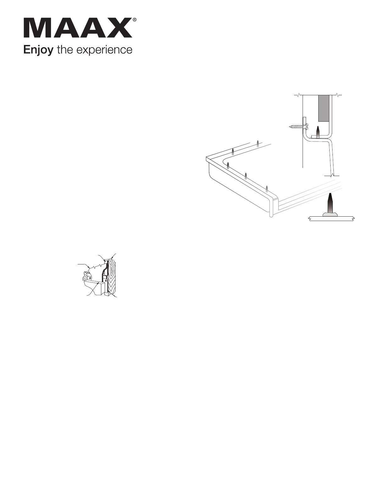
5. Plumb and level the unit in two directions: Place a level
on top of the apron, and along the finished flat area at the
top of the wall. Once the unit is leveled, in any gap
appears between the apron and sub floor fill the gap with
solid material. When satisfied with the fit, attach the unit
to framing with 6d galvanized nails or screws through the
pre-drilled holes in the mounting flanges. If required, drill
additional holes through the flanges in order to attach the
unit to each stud.
6. Make connections to supply and drain lines. Strap all
lines to the framing. Install finish trim. Caulk as necessary.
7. Check for leaks before installing wall-board and closing
off plumbing access.
8. Finish wall board as detailed in Figure 2.
5 .
6.
7.
8.
Plumb and level the unit in two directions:
Place a level on top of the apron, and along the
finished flat area at the top of the wall. Once the unit
is leveled, if any gap appears between the apron and
sub floor fill the gap with solid material. When satisfied
with the fit, attach the unit to framing with 6d galvanized
nails or screws through the predrilled holes in the
mounting flanges. If required, drill additional holes
through the flanges in order to attach the unit to each
stud.
Make connections to supply and drain
lines. Strap all lines to the framing. Install finish
trim. Caulk as necessary.
Check for leaks before installing wall-board and
closing off plumbing access.
board as
det
Shim Along
Framing
Wall
Board
M o u n t i n g
Flange
Caulk
Gap
Framing
Wood Support Shims
Two wood shims are provided in the installation
packet attached to the unit. Additonal shims may be
added by the installer.
It is MANDATORY that these wedges are in place
and in proper contact to assure structural integrity
of the bathing unit.
Figure 2
Figure 1
S IDE VIE W
INTEGRAL SELF-LOCATING
META L GUIDE PIN DETAI L
INTEGRAL SELF-LOCATING
META L GUIDE PINS PA N
BASE DETAIL
2. Place a continuous bead of silicone on base between the
edge of the base and the holes. For three and four piece
units, apply silicone up the ver tical seam(s) at the front or
inside edge of the wall. Also around the pin alignment piece.
3. Place the walls on the top of the base aligning the holes
with the pins. For three and four piece units, install the left
wall first. Repeating the same for the right wall. Press all
seams together to assure a tight fit. Wipe away any excess
caulking. See Figures 3-4
4. For four piece units, install the back wall first. Install the left
and right walls (Wet wall last). Press the seams together, to
assure a tight fit. Wipe away any excess caulking before it
cures.
5. Make sure all seams are even and in alignment with the
base section. Fasten the wall assembly to the framing using
6D galvanized screws through the mounting flanges. fasten
every 8’’ O.C. along the vertical flanges and to each framing
stud along the top, horizontally.
6. Make connections to supply and drain lines. Strap all lines to
the framing. Install finish trim. Caulk as necessary.
7. Check for leaks before installing wall-board and closing off
plumbing access.
8. Finish wall board as detailed in Figure 5.
Sectional bathing units are shipped from the factory with
screws or nuts and bolts connecting the parts together.
If installing the unit fastened together in one piece, follow
instructions on Page 1 of this manual.
The alignment pins should allow you to more easily install
the unit in the framing alcove. Read and understand the
instructions on this page since the alignment pins must be
inserted in a specific direction.
INSTALLATION PROCEDURE SECTIONAL SHOWERS
I. Install drain and/or overflow assembly on unit
following drain manufacturers instructions. Place support
wedges under the back edge and secure Place the base unit
in the install location. Level the unit. A minimum of two
shims should be used for proper support. (See Figure 4). Re-
check level and attach base to framing studs with 6D
galvanized screws.
Figure 3
Standard Sectional
Installation Instructions
CAUTION
If you use a RUBBER FLOOR MAT in this tub or shower
unit it must be removed after each usage. If left in the unit, it
DO NOT USE ABRASIVE CLEANERS
The most important caution is to avoid use of harsh
abrasive cleaners or gritty scouring powders. To clean the
unit, simply use a household liquid detergent with soft
sponge cloth and warm water. More persistent stains, tar,
or paint can be removed with naptha or mineral spirits.
Remove excess plaster by scraping with a sharpened soft
wood stick. Avoid wire brushes, metal scrapers or tools.
Restore dull areas by rubbing with automotive type body
cleaning compound.
Install drain and/or overflow assembly on unit
following drain manufacturers instructions.
Place support wedges under the back edge and secure
Place the base unit in the install location. Level the unit.
with adhesive. A minimum of two shims should be used
for proper support. (See Figure 5). Re-check level and
attach base to framing studs with 6D galvanized screws.
6.
Fiberglass Unit
silicone should make
act with bottom ledge of the base.
Silicone Bead
Plastic Fastener
er applying the
c fasteners for the
through the holes
(the wall to the left
acing the right and
firmly to the backside
he silicone to the
walls, insert them
the back wall. These
backside and pressed
fasteners fully contact the
pointing out towards
7.
Support Wedges
(Secure with adhesive)
Place a continuous bead of silicone on
base between the edge of the base and the holes
(As shown in Figure 4B). For three and four piece
units,apply silicone up the veritical seam(s) between
the holes for the fasteners and the front or inside edge
of the wall.
Figure 3
Figure 4B
Place the walls on top of the wooden blocks. One
by one remove the blocks taking care to align the
plastic fasteners into the holes in the underside of the
walls. For three piece units, install the left wall first.
Repeat for the right wall. Press all seams together to
8.
For four piece units, install the back wall first. Install
the left and right walls, (Wet wall last.) Take care to
align the plastic fasteners into the holes in the walls.
Press the seams together, to assure a tight fit.
Wipe away any excess caulking before it cures.
assure a tight fit. wipe away any excess caulking.
See Figure 5.
2
Figure 4
9.
10.
11.
12.
G 3838.51
Model No.
6824/25
6839
Fig 5
Fig 7
Fig 6
A
B
C
D
E
F
G
H
I
J
N/A
N/A
27
79”
73”
74”
74”
74”
73
73
73
39-1/2”
60-1/4”
32-1/4”
36-1/4”
48-1/4”
36-1/4”
48-1/4”
60-1/4”
39-1/2”
31-7/8”
33-1/2”
36-1/2”
37-5/8”
35-5/8”
31-1/4”
17-3/4”
14-3/4”
16-1/2”
18”
18”
16-1/8”
16-3/8”
14-1/2”
17-3/4”
17-3/4”
2-5/8”
16”
18”
24”
18”
24”
1-3/8”
14-3/4”
16-1/2”
18”
18”
16-1/8”
16-3/8”
14-1/2”
75”
76”
76”
76”
83-3/4”
83-3/4”
83-1/8”
83-1/8”
83-3/4”
83-3/4”
82”
82”
82”
81”
48”
19”
48”
48”
48”
48”
48”
17-1/2
42-1/4”
22”
22”
22”
22”
22”
43”
X
X
X
X
X
X
X
X
36-1/2”
Old No.
G 3838 NA 2P
G 6032 TS 2P
G 3232 SH 2P
G 3635 SH 2P
G 4836 SH 2P 1S
G 3636.53
G 6030.75
G 6036.71
6976/77
X
76”
60-1/4”
35-3/4”
15”
2”
15”
79”
82”
25-1/4
38-1/4”
G 6036.72
6880/81
X
81”
60-1/4”
37”
17-1/2”
1-5/8”
17-1/2”
81-1/4” 81-1/4”
22”
42-1/2”
G 6030.74
G 3232.50
G 3635.53
G 4835.54
G 4834.50
G 4834 3P 2S
G 3260 TS 3P N/A
G 5494 TS 2P N/A
G 4887 SH 3P 1S
N/A
X
X
X
60-1/4”
74”
32-3/4”
16”
N/A
16”
N/A N/A N/A
N/A N/A N/A
N/AN/AN/A
74”
54-1/4”
27-1/2”
12-1/4”
N/A
12-1/4”
N/A
N/A
N/A
78”
48-1/4”
35-3/4”
18-1/4”
24”
18-1/4”
FRAMING DIMENSIONS
Do not use abrasive cleaners
If you use a RUBBER FLOOR MAT in this
tub or shower unit it must be removed after each
usage. If left in the unit, it may cause blisters or
damage to the surface finish.
G 6017 TS 2P
N/A
X
81”
60-1/4”
37-3/4”
16”
N/A
16”
N/A
N/A
N/A N/A
G 4887 SH 2P 1S
N/A
X
78”
48-1/4”
35-3/4”
18-1/4”18-1/4”
24”
18-1/4”
N/A
N/A
N/A
N/A
G 3679 SH 3P
N/A
X
78”
36-1/4”
37”
19”
18”
19”
N/A
N/A
N/A
N/A
G 3687 SH 2P
X
N/A
79”
36-1/4”
36-1/4”
17-1/2”
18”
17-1/2”
N/A
N/A
N/A
N/A
G 3275 SH 2P
X
N/A
77”
32”
34”
19-1/2”
16”
19-1/2”
N/A
N/A
N/A
N/A
Praxis Companies LLC.
435 Industrial Road
Savannah, TN. 38372
Phone: (800) 443-7269
Fax: (731) 925-7656
Make sure all seams are even and in alignment
with the base section. Fasten the wall assembly
to the framing using 6D galvanized screws through the
mounting flanges. Fasten every 8” O.C. along the vertical
flanges and to each framing stud along the top, horizontally.
The most important caution is to avoid use of harsh
abrasive cleaners or gritty scouring powders. To clean
the unit, simply use a household liquid detergent with
soft sponge cloth and warm water. More persistent
stains, tar, or paint can be removed with naptha or
mineral spirits.
Remove ex
cess plaster by scraping with a sharpened
soft wood stick. Avoid wire brushes, metal scrapers
or tools. Restore dull areas by rubbing with automotive
type body cleaning compound.
CAUTION:
Make connections to supply and drain
lines. Strap all lines to the framing. Install finish
trim. Caulk as necessary.
Check for leaks before installing wall-board and
closing off plumbing access.
Finish wall
board as
detailed in
the diagram.
Shim Along
Framing
Wall
Board
M ou nt in g
Flange
Caulk
Gap
Framing
Figure 5
may cause blisters or damage to the surface finish.
©
2018, MAAX Bath
Customer Service: 1-877-438-6229
www.maax.com
Standard Sectional
Installation Instructions
Sectional AcrylX
TM
Tub/Showers
Sectional AcrylX
TM
Showers
Praxis Companies warrants to the owner of its Tub/Shower units as follows:
Units manufactured of fiberglass reinforced polyester resin, that it will, free of charge, repair or exchange as its option, any Praxis Companies unit found to be defective
in materials or workmanship upon inspection by an authorized representitive of Praxis Companies for a period of three (3) years from date of purchase. The exchange
of a unit is limited to supplying a replacement unit of comparable size and style and does not include any costs of removal or installation.
This warranty shall be voided if the unit is moved from its place of initial installation or is not installed in accordance with the instructions supplied by the manufacturer
of the unit. Further, this warranty does not apply if the unit has been subjected to accident, abuse, misuse, damage caused by flood, fire or
act of God.
Since local code requirements vary greatly throughout the country, distributers, dealers, installation contractors and users of plumbing products should determine whether
there are any code restrictions on the use of a specific product. Praxis Companies makes no representation or warranty regarding and shall not be responsible for
LIMITED WARRANTY
D
L
C
OUTLET
C
B
E
/
2”
1
8
L
C
Fittings
L
C
A
G
J
I
Shower
H
Blocking
(optional)
Shower Head
and Fittings
L
C
F
Header for
Optional
Dome
Shower Head
and Fittings
L
C
Header for
Optional Dome
F
H
G
J
Shower
L
C
Blocking
(optional)
A
I
Fittings
L
C
E
B
D
C
Outlet
C
L
Spout
Figure 7
Figure 8
11
13”
1”
4
13”
Required for
G 6036.72
©
2018, MAAX Bath
Customer Service: 1-877-438-6229
www.maax.com 10038626 2018-07-25
LIMITED WARRANTY — UNITED STATES
This warranty extends only to the original owner/end-user for personal
household use. For commercial uses, additional limitations apply.
For accessing product Limited warranty please visit:
www.maax.com/us-warranty
This warranty extends only to the original owner/end-user for personal
household use. For commercial uses, additional limitations apply.
For accessing product Limited warranty please visit:
www.maax.com/ca-warranty
LIMITED WARRANTY — CANADA
  • Page 1 1
  • Page 2 2
  • Page 3 3
  • Page 4 4

MAAX 106551-L-000-002 MX QSI-6030-SH 4 in. (5-Piece) Installation guide

Type
Installation guide

Ask a question and I''ll find the answer in the document

Finding information in a document is now easier with AI