Page is loading ...

Low Threshold Gelcoat Shower with Molded Seat
OWNER’S MANUAL
6032 SH 1S 3P 6032 SH 1S 3P

ellasbubbles.com | 1
Tools/ materials you might need for proper installation
• 6D galvanized screws
• 100% clear silicone caulking
• caulking gun
• color match surface caulk
• shims
• tape measure
• 1/8” countersunk drill bit
• power drill
• cardboard
• china marker or grease pencil
• furring strips
• construction adhesive
• long spirit level
• mortar mix
• 2’-3’ sections of 1/2” PVC pipe
• plumb bob tool
DO’S & DON’TS
1. The back of a berglass unit is not waterproof. Unit must be
stored so water will drain o and not accumulate in one spot.
Water can penetrate the back laminates and soak the glassed in
reinforcement supports causing bulges in the gelcoat surface.
2. Most handling damage is the result of impact blows to the back
of the berglass units.
3. Never drag a berglass unit on any surface. Always transport
the unit by hand using (2) people or two wheel dolly.
4. Never let a berglass unit drop from any height, not even an
inch or stress cracks are likely to occur.
5. Placing objects inside the unit can cause scratches or nicks to
the nished surface. Do not use the shower as a trash receptacle!
Always place a drop cloth or cardboard on the oor when working
inside the shower.
6. Never clean berglass gelcoat surface with metal tools of any
kind, including razor blades.
PLANNING YOUR INSTALLATION―WHAT YOU NEED TO
KNOW BEFORE GETTING STARTED
1. Gather the items needed (listed above).
2. Carefully remove the old bathtub at the installation site. The
replacement showers are 77” tall so wallboard should be removed
on all three walls to at least this height. Measure the framing
pocket to insure the framing area and stud walls are square and
measures: 60 1/4” wide x 33 1/4” deep. The oor must be clean,
solid, and level. Relocate drain in oor if required. There is a 6”
cutout around the drain area.
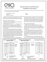
See framing diagram in Figure 1 for more information.
3. Review the framing diagram in Figure 1. Modify existing framing
if required. For new construction, build framing structure in
accordance with product dimensions and notes shown in the
framing diagram.
4. The shower base will be installed, leveled, and fastened to the
framing before the walls are installed. Shimming is recommended.
See Figure 2
5. Always place cardboard or a drop cloth on the shower oor and
top of seat to protect the nished surface from scratching and
damage.
6. When installed, the wall sections will not be mechanically
fastened together, or to the shower base. The wall sections will be
installed tight to each other and the shower base with the silicone
in the seams providing a water resistant seal. These positions
will be maintained when the shower anges are fastened to the
framing. The base must be solidly installed so the seams between
the shower base and wall sections will not separate, allowing
water to penetrate the wall cavity.
INSTALLATION WARNING: This model is not designed to be installed
as a one piece unit. The base shall be self supported with provided
wood shims to support the shower base, and fasteners shall support
the anges prior to installation of the wall sections. This procedure
will ensure caulked joints or seams will not separate, allowing water
to penetrate the wall cavity. FAILURE TO COMPLY WITH INSTALLATION
INSTRUCTIONS MAY VOID YOUR WARRANTY.
NOTE: Your level and your plumb bob may tell you the framing is not perfectly square or level. This is a common experience. Do not assume
your stud walls are straight or plumb. Adjustments to your vertical framing and suboor are most often necessary.
Low Threshold Shower with Molded Seat
Gelcoat & Solid Surface Bathware

3P Shower Installation Instructions
Gelcoat & Solid Surface Bathware
ellasbubbles.com | 2
FRAMING DIAGRAM FOR 3 PIECE SHOWER
Box out for sub oor 6” x 6”
core minimum size required
* Framing pocket required to provide 60” mim-
imum and 60 1/4” maximum width x 33 1/4” deep
FIGURE 1
FIGURE 2 FIGURE 3
Wood Shims

3P Shower Installation Instructions
Gelcoat & Solid Surface Bathware
ellasbubbles.com | 3
INSTALLATION INSTRUCTIONS
1. Carefully remove the three parts from the packaging and
inspect the shower closely for any shipping damage.
It is very important to dry assemble the shower in an open space
for the purpose of inspecting the shower for t, nish and defects
before moving the shower into the construction area. Check to
ensure that the gaps are consistent. You may notice the front
corners of the wall are slightly pulled inward up to 1/2”. This is
normal as the wall will ex and pull into the studs.
Report any damage, defects and concerns. At this point take
digital photos as a time stamp document. This will protect your
investment, verify the condition of the product- as it was received,
speed the assessment and correction process if required.
Disassemble the shower and set the wall sections o to the side
and move the shower base in front of the framing pocket opening.
2. Use care when handling the shower parts to avoid scratches or
stress cracks from excessive exing.
3. Install the drain tting on the shower. Follow drain
manufacturers instructions. The manufacturer is not responsible
for leaking drain connections.
4. Place cardboard or a drop cloth on the shower oor and on the
top of the seat to avoid scratching the surface.
5. Locate wood shims in the framing pocket. Carefully measure
to ensure the proper placement of these shims so they are
supporting the back edge of the shower base. These shims may be
placed after the base is installed if the framing is open as shown
in Figure 2.
If rear access is not available, a thin-set mortar mix may be used
in place of shim to ll the gap beneath the support leg and the
sub oor. Pour thin-set mortar mix to a minimum height of 1 inch
in the area directly below the support leg only to ensure proper
base to oor contact. Do not step into shower before leveling and
fastening to stud wall with screws.
6. Carefully place the shower base into framed pocket. TIP: Place
two 3 foot sections of PVC pipe on the oor beneath the front
apron of the pan as shoe horns or slides to assist.
Use care not to knock the support shims loose or disturb mortar
bed when moving base into permanent position.
FIGURE 4
FIGURE 5
FIGURE 6
FIGURE 7

3P Shower Installation Instructions
Gelcoat & Solid Surface Bathware
ellasbubbles.com | 4
Do not slide shower base on protruding drain tting. See Figure 3
7. Once unit is perfectly level, use marker or grease pen to mark
studs at top and bottom edge of anges as a visual guide. Use 1/8”
countersinking bit to drill pilot holes. Recheck Level as you fasten
to studs to ensure base has not shifted o level. See Figures 4
and 5
8. If shims are used, check the wood support shims to be certain
they are tightly wedged in between the oor surface and the back
leg of the shower. Once the shims are in place glue or nail the
shims to the sub oor to eliminate any movement. See Figure 6
9. Your shower base shall be equipped with one vertical alignment
pin protruding from the base located on the center of back wall
toward seat side of shower. This pin properly aligns the rst back
wall panel to be installed.
10. Drill holes with the 1/8” countersink drill bit. Using 6D
galvanized screws, secure the shower base to the framing. Tighten
the screws snug and tight to the gelcoat surface, but be careful
not to over tighten and break berglass ange. It is recommended
to use countersinking drill bit which will allow the screw head to
be ush with the ange surface. Large screw heads can protrude
interfering with wall assembly. See Figure 7
NOTE: Shims or furring strips may be used to assure solid contact
between the berglass mounting ange and the studs.
11. Complete a nal check to ensure your base is level, secured to
all three walls, the support leg makes contact with the suboor
and you have a slope to the drain. Now you can complete the
shower drain connection. See drain instructions.
12. Dry-t the seat wall rst. The center grout lines of the base and
wall should align. See Figure 9
You will nd a single alignment hole on the bottom of the seat side
wall panel.
If the base is level and the wall studs are vertically plumb, the wall
will rest properly with consistent gap line.
NOTE: If gap is larger in the corner the base is not level or the stud
wall is not plumb. Notching the stud wall to allow the wall to rest
level on the base may be necessary. The dry t inspection procedure
in step one conrms your shower if pre-aligned and free of defect.
Compare the gap with the photos of the shower you took during dry-t
procedure. Correction is needed if the gaps look dierent.
Once seat side wall panel aligns properly and gaps are consistent,
dry t valve wall panel before installing valve on stud wall. When
both panels align properly remove both panels.
FIGURE 8
FIGURE 9
FIGURE 10

3P Shower Installation Instructions
Gelcoat & Solid Surface Bathware
ellasbubbles.com | 5
Prepare the seat side wall for permanent installation. Apply a
bead of caulk on the shower base from the front corner to the
center line of back wall using 100% clear silicone adhesive caulk.
This procedure will prominently adhere the wall to the base and
seal o any moisture from the wall cavity.
NOTE: Cosmetic caulking will be required in a later step.
Place wall on base and align into permanent position. Drill holes
through anges and secure ange to stud wall using at head
screws drawing the panel to the wall until wall and base surface is
equally aligned.
NOTE: Panel may need to be pulled to the stud on the front side of the
wall shimming where necessary.
13. After mounting the valve to the stud wall, carefully transfer
the valve location to the wall panel. Cover the surface area with
masking tape to prevent chipping of nish before cutting hole.
After the valve hole(s) are cut, lift the wall back into place to trial
t. Adjust holes or valve if necessary, keeping in mind the need to
make sure the seams and grout lines continue to line up and there
is a consistent gap on vertical and horizontal seams.
NOTE: Plumb stud walls and level oors are the exception rather then
the norm. Some adjustment is usually necessary. When the valve
location is correct and the gap is visually consistent on vertical and
horizontal seams, your dry t procedure is complete.
14. Temporality remove the valve wall o the base to prepare for
permanent installation.
Permanently install the wall by angling the wall to align the center
seam pins. Rotate wall to clear the rough in valve.
NOTE: Run an unbroken bead of caulk the entire length of the halfway
point and circle shipping bolt holes and pin.
See Figure 11: Use 100% clear silicone adhesive caulk on horizontal
and vertical interior joint surfaces. Color surface caulking will be a
later step. Clear caulking on inner seam is recommended.
15. Push center seam together hand tight. Wipe clean any excess
caulk that squeezes out from the interior seal.
FIGURE 11
FIGURE 12
FIGURE 13
* Apply silicone to front side of ridge

3P Shower Installation Instructions
Gelcoat & Solid Surface Bathware
ellasbubbles.com | 6
16. Measure, and mark locations for mounting holes on the
anges of the wall panels. Mark horizontal so each hole matches
up with a stud, (16” on center). Mark every 8” on center for the
vertical anges at the front of the unit. Drill a 1/8” diameter screw
hole at each mark.
Use 6D fastener screws to draw nailing ange to wood studs. Shim
where necessary.
RECOMMENDED CAULKING
ALL GELCOAT FINISH MODELS:
100% RTV silicone adhesive caulk- clear, or matching white or
bone for inside the seam.
ALL SOLID SURFACE FINISH MODELS:
Two caulks recommended for best results: For seams (areas that
will not be visible) 100% RTV clear silicone adhesive. The function
of this caulk is to mechanically bind the shower parts together.
For Visible Surfaces - premium color matching caulk for cosmetic
function to blend with surface and erase seams.
17. Surface caulk all joints with a premium color match caulk
wiping all surface excess clean.
See caulk instructions for proper curing time before use of shower.
See Figure 12. See close up view in Figure 13
Assure that the vertical and horizontal grout lines remain in
alignment. Fasten the vertical anges at the front on both walls.
Install nish trim around the water control valve, per the
manufacturers provided instructions.
18. Apply premium color matching surface caulk to nish seams.
Smooth caulk and clean away excess before cure. See caulk
directions for curing time. Do not use shower until caulk is cured.
© 2016
FIGURE 14

3P Shower Installation Instructions
Gelcoat & Solid Surface Bathware
ellasbubbles.com | 7
INSTALLATION DIAGRAM
UNDER SIDE VIEW OF BASE SIDE VIEW OF BASE
3 Pins at center seam
1 Pin on base
Add form shim to bottom of leveling leg
Trim Foam 1” wide x 38” long
Glue foam to bottom of leveling leg
Wood bottom boards

ellasbubbles.com | 8
Copyright May 2016
LIMITED WARRANTY
Ella’s Bubbles, LLC., distributor of private labeled showers, manufactured by Praxis Companies for Ella’s Bubbles, warrants by Praxis
Companies to the owner of its gelcoat berglass shower units as follows:
Units manufactured of berglass reinforced polyester resin, that it will, free of charge, repair any Praxis Companies unit found to be
defective in material or workmanship upon inspection by an authorized representative of Praxis Companies for a period of thirty (30)
years from the date of purchase.
The exchange of a unit is limited to supplying a replacement unit of comparable size and style and does not include any cost of removal
or installation.
Any component part supplied by Praxies Companies carries the same limited warranty provided by our supplier for a period of one (1)
year. Any Praxis Companies product will carry a thirty (30) year limited warranty against manufacturing defects. This warranty shall
be voided if the unit is moved from its place of initial installation or is not installed in accordance with the instructions supplied by
the manufacturer of the unit. Further, this warranty does not apply if the unit has been subjected to accident, abuse, misuse, damage
caused by ood, re, or act of God.
The owner agrees by use of the unit that the obligations of Praxis Companies shall not exceed to contingent or indirect damage or
injury to the structure of its contents, that the obligations of Praxis Companies are limited to those set forth herein, and that no other
obligations, expressed or implied, are assumed by Praxis Companies or Ella’s Bubbles.
All mailing notication must be sent via certied mail to:
Ella’s Bubbles, LLC.
Warranty Department
2101 S. Carpenter Street
Chicago, IL 60608
Email: info@ellasbubbles.com
TOLL FREE: 1-800-480-6850
Low Threshold Shower with Molded Seat
Gelcoat & Solid Surface Bathware

Warranty Activation Form
ellasbubbles.com | 9
Upon completing the installation of an Ella Walk In Bath, the following Warranty Activation Form must be completed, signed by both
the customer and installer, and returned to Ella’s Bubbles, LLC. In order for the Warranty to be activated (faxed, scanned, or emailed,
or hard copy mailed).
TO BE INITIALED BY THE INSTALLER(S)
_________ Tub is level in all directions and all support legs are touching the ground.
_________ Tub is installed on a dedicated 30 Amp GFCI protected circuit using 10 gauge wire
_________ Frame of the tub has been properly grounded.
_________ Door Seal has been cleaned with rubbing alcohol to remove any dust or debris left over from construction.
_________ Temperature Control Valve operated on both hot and cold settings.
_________ Both diverters function properly.
_________ Hand Shower functions on all settings without leaking.
_________ All supply lines have been checked for leaks while both diverters are on.
_________ Drains open and close properly, and the locking nut has been tightened on both stoppers.
_________ Door seal is water tight after tub has been lled for a minimum of 20 minutes.
_________ After running for a minimum of 20 minutes both the Hydro and Air Pumps are functioning properly and all connections to
the pumps and jets are water tight.
_________ Chromatherapy Light and the Ozone Sterilization are working properly. (When the Ozone is on by itself it will make a light
humming noise).
_________ All drain ttings have been checked for leaks while the tub is draining.
_________ Unit is installed with access to both plumbing and electrical connections.
INSTALLER’S INFORMATION
Name
Address City State Zip
Telephone Email
Date
Signature

ellasbubbles.com | 10
Warranty Activation Form
OWNER’S INFORMATION
Name
Address City State Zip
Telephone Email
Date
Signature
Place of Purchase
Model Serial Number
Purchase Date Purchase Price
Contact Name Telephone
** Copy of sales receipt must be included with warranty activation forms.
To activate manufacturer’s warranty, please complete both pages and use one of the following options below to submit.
Mail: Ella’s Bubbles, LLC.
Warranty Department
2101 S. Carpenter Street Chicago, IL 60608
Fax: 1-312-666-3551
Email: warranty@ellasbubbles.com
/
