Page is loading ...

M-Bus Mster MultiPort 250D
Instlltion nd User Guide
Kmsrup A/S · Indusrivej 28, Silling · DK-8660 Sknderborg · T: +45 89 93 10 00 · info@kmsrup.com · kmsrup.com

2 Kmstrup A/S • 5512853_D2_GB_10.2019
M-Bus Mster MultiPort 250D
Contents
1 Introduction 4
1.1 Design 4
2 Functionlity 5
2.1 Overview of functions 7
3 Connections 8
3.1 Overview of connections 9
3.2 Power supply 10
3.3 USB 10
3.4 RS-232 14
3.5 RS-485 15
3.6 Opticl eye 15
3.7 M-Bus Output 15
3.7.1 Current nd voltge 15
3.8 M-Bus Repeter Input 16
4 Cbling 17
4.1 Specil fetures of
M-Bus Mster MultiPort 250D 18
4.2 Electricl conditions in n M-Bus network 18
4.2.1 M-Bus modules 18
4.3 Instlltion prmeters 18
4.3.1 Cble 19
4.3.2 Cble topology 20
4.3.3 Exmples of network sizes 23
5 M-Bus ddressing 24
5.1 Primry ddressing 24
5.2 Secondry ddressing 24
5.3 Enhnced secondry ddressing 24
6 M-Bus communiction 25
6.1 Communiction speed 25
6.2 Trnsprent reding 25
7 Opertion of M-Bus Mster MultiPort 250D 25
7.1 Keys 26
7.2 Light emitting diodes 26
7.2.1 Power 27
7.2.2 Request 27
7.2.3 Dt 27
7.2.4 Overlod 27
7.3 Disply 27
7.4 Menu overview 28

3Kmstrup A/S • 5512853_D2_GB_10.2019
M-Bus Mster MultiPort 250D
7.5 Meter serch by mens of MultiPort 250D 28
7.5.1 Primry scnning 29
7.5.2 Secondry scnning 30
7.6 Meter reding by mens of MultiPort 250D 31
7.6.1 Meter reding fter scnning 31
7.6.2 Meter reding from the menu Red Meter 32
7.7 Reding M-Bus loggers by mens of
MultiPort 250D 32
7.7.1 Red Logger 32
7.7.2 Disply of logged dt 33
7.8 Settings of MultiPort 250D 34
7.8.1 Dte nd time 35
7.8.2 Contrst 35
7.8.3 M-Bus 35
7.9 Green Mode 37
7.10 Other settings 37
7.11 PIN code 38
7.12 Advnced 38
7.12.1 Reding specific meter vi the
M-Bus ddress 39
7.12.2 Reding meter vi secondry ddress 39
7.12.3 View Lst Meter Reding 39
7.12.4 Network Troubleshooting 40
7.12.5 Informtion loggers 40
7.12.6 Fctory settings 41
7.12.7 Communiction Test 41
7.12.8 Bus Info 42
7.12.9 Restrt mster 42
7.12.10 About M-Bus Mster MultiPort 250D 42
8 Web Server 43
9 Dimensioned drwings 44
10 Technicl dt 45
11 Ordering numbers 46

4 Kmstrup A/S • 5512853_D2_GB_10.2019
M-Bus Mster MultiPort 250D
1 Introduction
M-Bus is bus system, which is specilly suited for reding wter, het, cooling, gs nd electricity consumption
meters.
An M-Bus system consists of n M-Bus Mster nd number of meters with M-Bus interfce. A network cn include
different meter types nd brnds. The cble type used is typiclly twisted pir copper.
The connected meters re red either directly by the mster with dt ppering on the mster’s disply or by reding
progrm which is connected to one of the mster’s communiction ports.
The mster powers the M-Bus slve modules in the meters. Bttery supplied meters thereby chieve longer bttery
lifetime.
The mximum size of n M-Bus network using Kmstrup M-Bus Mster MultiPort 250D is 250 meters. If number of
msters re configured s repeters nd coupled in cscde nd only secondry ddressing is used, totl of 1,250
meters cn be connected, nd the totl cble length cn be up to pprox. 14 km.
If primry ddressing is used, up to 250 meters cn be connected.
Communiction in the M-Bus network is synchronous seril bit trnsmission in hlf duplex, which mens tht it is only
possible to communicte in one direction t time.
Communiction speed cn be 300, 2400 or 9600 bud.
It is not necessry to connect PC to the mster during instlltion, mintennce nd troubleshooting in the M-Bus
network s the mster itself includes the functions needed. Opertion is crried out vi disply nd front keys.
M-Bus is stndrdized ccording to EN 13757-2 nd EN 13757-3.
1.1 Design
M-Bus Mster MultiPort 250D is built into solid cbinet, which complies with protection clss IP 67.
The front consists of bcklit LCD, 6 keys, 4 sttus LEDs nd n opticl eye.
The power supply is switch mode type which enbles you to connect the mster to power supply between 100 nd
240 volts. The frequency must be 50-60 Hz.

5Kmstrup A/S • 5512853_D2_GB_10.2019
M-Bus Mster MultiPort 250D
2 Functionlity
Kmstrup M-Bus Mster MultiPort 250D is n M-Bus mster designed for the connection of up to 250 meters with
M-Bus interfce. The cble length of mster cn be up to 2800 m depending on cble type.
The mster supports primry, secondry nd enhnced secondry ddressing. Enhnced secondry ddressing is
supported when the mster is used s level converter, not when reding vi the disply.
All inputs re glvniclly seprted from the M-Bus network.
When designing the mster, it hs been considered importnt tht instlltion nd nlysis work cn be effected
directly from the mster without hving to connect PC with dedicted softwre.
Configured s mster, MultiPort 250D is operted vi its disply nd the six front keys.
The disply hs been designed with user-friendly menu structure, which mkes it simple to perform scnning,
reding nd nlysis of the M-Bus network. Furthermore, the disply currently provides informtion on network sttus
such s current communiction nd number of connected meters (Unit Lods).
Configured s level converter, one or severl of the integrted communiction ports re connected to reding
system, control unit or similr. Communiction is controlled from the connected units.
MultiPort 250D cn be ccessed from ll vilble communiction ports. The integrl port controller prevents collision
in cse of simultneous communiction through more thn one port.
When the port controller detects communiction on one port, communiction on other ports becomes impossible.
When communiction on one port is finished, ll ports re open to communiction.
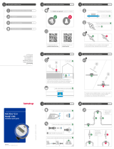
The repeter function mkes it possible to extend the size of the M-Bus network both s to number of meters nd totl
cble length. If one mster nd four repeters re instlled in network, the totl cble length cn be extended to
pprox. 14 km, nd up to 1250 meters cn be connected.

6 Kmstrup A/S • 5512853_D2_GB_10.2019
M-Bus Mster MultiPort 250D
602
602
602
602
602
602
602
602
602
602
602
602
602
602
602
602
602
602
602
602
250 meters 250 meters 250 meters
With 4 repeters, up to 1250
meters nd 14 km cble length
M-Bus Mster
M-Bus Repeter M-Bus Repeter ......
Up to 14 km2.8 km2.8 km
RS-232, RS-485, USB
RS-232: 15 m
RS-485: 1200 m
USB: 5 m
24+25
24+25
24+25
24+25
24+25
24+25
24+25
24+25
24+25
24+25
24+25
24+25
24+25
24+25
24+25
24+25
24+25
24+25
24+25
24+25
24+25
24+2553+5424+2553+54
The integrted web server enbles remote opertion of the mster s to configurtion, scnning nd reding vi RS-
232, RS-485 nd USB.
Opertion vi keys nd communiction through the opticl eye cn be protected by PIN code.
Four light emitting diodes indicte the sttus of mins supply, dt communiction s well s possible overlod nd
short-circuit of the M-Bus network.
Kmstrup M-Bus Mster MultiPort 250D hs been designed for instlltion indoors. The protection clss cn be up to IP
67.

7Kmstrup A/S • 5512853_D2_GB_10.2019
M-Bus Mster MultiPort 250D
2.1 Overview of functions
• Usble s mster, repeter nd level converter
• Bcklit 128 x 64 pixels LCD
• Reding vi disply of both Kmstrup meters nd third-prty brnds
• Supports primry, secondry nd enhnced secondry ddressing
• Collision detection with brek signl
• Up to 250 slves per mster
• Integrted repeter function
• Up to four repeters in system = totl of 1250 meters
• Up to 14 km cble length
• 300, 2400, nd 9600 bud communiction speed
• Byte recovery
• Echo suppression
• Trnsient protection
• Integrted USB, RS-232, RS-485 nd opticl eye with utomtic port controller
• All ports re trnsprent nd glvniclly seprted from the M-Bus network
• Integrted web server for remote configurtion, nlysis nd reding
• PIN code protection of keybord nd opticl eye
• Event loggers for M-Bus mster nd M-Bus network
• Cble connection vi 9 PG cble glnds
• Locl nd remote updte of firmwre for future functionlity
• Up to IP 67 protection clss.

8 Kmstrup A/S • 5512853_D2_GB_10.2019
M-Bus Mster MultiPort 250D
3 Connections
All connections in MultiPort 250D re screw terminls
with mx. cble size of 2 mm2.
The protection clss of M-Bus Mster MultiPort 250D cn
be up to IP 67. IP 67 mens full dust protection s well
s wter tightness for minimum 30 minutes down to 1
metre.
In order to obtin the highest IP protection, the cbles
used must be correctly mounted through the mster’s
unions.
USB RS-485
RS-232 4 sets of
M-Bus outputs
M-Bus input for
cscde mode
Mins 100-230 V
50/60 Hz

9Kmstrup A/S • 5512853_D2_GB_10.2019
M-Bus Mster MultiPort 250D
3.1 Overview of connections
Connection number on
mster
Designtion Colour/connector No. Description
Power supply
134 N Blue Neutrl
135 L Brown Live
136 PE Yellow/green Protective erth
USB 2.0 Mx recommended cble length: 5 m
130 VCC Red/1 5 V power supply
131 D- White/2 Dt -
132 D+ Green/3 Dt +
133 GND Blck/4 Ground
RS-232 Mx recommended cble length: 15 m
105 RxD 2 Received Dt
106 TxD 3 Trnsmitted Dt
107 GND 5 Ground
108 DTR 4Dt Terminl Redy
109 CTS 8 Cler To Send
111 DSR 6 Dt Set Redy
112 RTS 7Request To Send
RS-485 Mx recommended cble length: 1,200 m
137 A/- Trnsmit/Receive inverted
138 A+ Trnsmit/Receive non-inverted
139 GND Ground
M-Bus Repeter Input Jumper must be set to Repeter
53 L1 M-Bus input to mster in repeter mode
54 L2 M-Bus input to mster in repeter mode
M-Bus Mster Output 4 sets connection terminls, connection in prllel
24 L1 M-Bus output from mster to meters
25 L2 M-Bus output from mster to meters

10 Kmstrup A/S • 5512853_D2_GB_10.2019
M-Bus Mster MultiPort 250D
3.2 Power supply
The power supply of M-Bus Mster MultiPort 250D is the switch mode type which requires voltge between 100 V nd
240 V. The frequency cn be 50 Hz or 60 Hz.
The mins cble is connected to the mster through the ssocited glnd. The dimeter must be between 4 nd 8 mm.
The mster is supplied without mins cble nd we recommend fixed instlltion, i.e. without using mins plug s
this would reduce relibility of opertion.
3.3 USB
M-Bus Mster MultiPort 250D’s USB connection cn be used for M-Bus communiction on n equl bsis with the other
seril connections.
The following communiction speeds cn be used for M-Bus communiction:
• 300 bud 8E1
• 2400 bud 8E1
• 9600 bud 8E1
USB version 2.0, which llows up to 5 m cble length, is used. In connection with other USB versions thn 2.0, the
mximum cble length recommended is 3 m.
The mster’s integrted port controller mkes sure tht communiction is only possible on one seril port t time.
The mster is vilble with fctory-mounted 145 cm cble fitted with USB connector type A.
1 2 3 4
USB connector type A
To be ble to communicte with M-Bus Mster MultiPort 250D vi USB, the corresponding USB driver must be instlled
on the computer used for reding.
The progrm is vilble on Kmstrup’s home pge.

11Kmstrup A/S • 5512853_D2_GB_10.2019
M-Bus Mster MultiPort 250D
From www.kmstrup.com, nvigte to ”Service & Support”, nd click on “Go to downlods”.
On the new pge, scroll down to the „M-bus Mster“ re, clik on “Go to downlod”, nd you will see this pge:
Click the „Downlod USB driver“ link. You will now be sked to select „Run“ or „Sve“. When selecting „Run“, the
instlltion strts utomticlly.
When the progrm is retrieved, it is sved under C:\Kmstrup\M-Bus Mster 250D.
When selecting „Sve“, the popup br chnges to:
Click “Run”, or “Open folder” to run “KmstrupMBusUSB.exe”.

12 Kmstrup A/S • 5512853_D2_GB_10.2019
M-Bus Mster MultiPort 250D
When the setup progrm hs been strted, just follow the instructions in the wizrd.
Click ”Next” to continue or ”Cncel” to stop the setup.

13Kmstrup A/S • 5512853_D2_GB_10.2019
M-Bus Mster MultiPort 250D
The Device Driver Instlltion wizrd strts to run.
Depending on the security settings in your computer, this
popup my occur.
Pressing „Finish“, the instlltion is completed.

14 Kmstrup A/S • 5512853_D2_GB_10.2019
M-Bus Mster MultiPort 250D
3.4 RS-232
M-Bus Mster MultiPort 250D’s RS-232 connection cn be used for M-Bus communiction on n equl bsis with the
other seril connections.
The following communiction speeds cn be used for M-Bus communiction:
• 300 bud 8E1
• 2400 bud 8E1
• 9600 bud 8E1
Mximum recommended cble length is 15 m.
The mster’s integrted port controller mkes sure tht communiction is only possible on one seril port t time.
The mster is vilble with fctory-mounted 145 cm RS-232 cble fitted with DB9F femle connector.
1
2
3
4
5
6
7
8
9
RS-232 connector type DB9F

15Kmstrup A/S • 5512853_D2_GB_10.2019
M-Bus Mster MultiPort 250D
3.5 RS-485
M-Bus Mster MultiPort 250D’s RS-485 connection cn be used for M-Bus communiction on n equl bsis with the
other seril connections.
The following communiction speeds cn be used for M-Bus communiction:
• 300 bud 8E1
• 2400 bud 8E1
• 9600 bud 8E1
Mximum recommended cble length is 1,200 m.
The mster’s integrted port controller mkes sure tht communiction is only possible on one seril port t time.
3.6 Opticl eye
M-Bus Mster MultiPort 250D’s opticl eye cn be used for M-Bus communiction on n equl bsis with the other
seril connections.
The following communiction speeds cn be used for M-Bus communiction:
• 300 bud 8E1
• 2400 bud 8E1
• 9600 bud 8E1
The mster’s integrted port controller mkes sure tht communiction is only possible on one seril port t time.
3.7 M-Bus Output
All meters in n M-Bus network re connected to M-Bus output terminls 24 nd 25. The mster includes four sets of
connections coupled in prllel.
3.7.1 Current nd voltge
Bus mrk/spce 41 V DC/28 V DC
Detection level, communiction 7 mA
Detection level, collision 25 mA
Mx norml operting current 375 mA
Wrning level, operting current 377 mA - Overlod LED flshes
Overlod level, operting current 500 mA - Overlod LED is constntly illuminted

16 Kmstrup A/S • 5512853_D2_GB_10.2019
M-Bus Mster MultiPort 250D
3.8 M-Bus Repeter Input
Kmstrup M-Bus Mster MultiPort 250D cn be used s
both mster nd repeter.
Used s mster, up to 250 meters cn be connected in
n M-Bus system.
The repeter function mkes it possible to extend the
size of the M-Bus network both s to number of meters
nd totl cble length. If one mster nd four repeters
re instlled in network, the totl cble length cn be
extended to pprox. 14 km, nd up to 1250 meters cn be
connected.
The mster is configured s repeter by plcing the
jumper on the connector mrked Repeter. Using n
M-Bus Mster MultiPort 250D s repeter, the M-Bus
network in front of the repeter is connected to ”M-Bus
Repeter In” on terminls 53 nd 54. The following meters
re connected to M-Bus Out on terminls 24 nd 25.
Position of mster/repeter jumper.
Setting s mster or repeter.

17Kmstrup A/S • 5512853_D2_GB_10.2019
M-Bus Mster MultiPort 250D
The mster’s disply shows tht it is
configured s repeter.
When the mster is configured s
repeter, only the menu points which
cn be used with this configurtion
re displyed.
250D configured s repeter. Min menu when 250D is configured s
repeter.
If the repeter is not connected to mster or repeter vi terminls 53
nd 54, the symbol shown in the top right-hnd corner is displyed.
Note: The power supply MUST be switched off during reconfigurtion
between mster nd repeter.
4 Cbling
Typiclly unshielded twisted pir cble up to pprox. 1.5 mm2 is used. The cbling topology is typiclly str or bus or
combintion of both. The connection in M-Bus is independent of polrity nd no termintion resistnce t the end of
the cbling is needed.
If cble type with shield is used, it is importnt tht the two M-Bus conductors re not connected to ground or shield.
No precise indiction s to mximum cble length in n M-Bus network cn be given s it depends on vrious
prmeters.
The two most importnt prmeters to consider when selecting cble for n M-Bus instlltion re cble resistnce
nd cble cpcity. Generlly speking, the resistnce limits the number of M-Bus slves, nd the cpcity limits the
communiction speed.
Furthermore, we recommend keeping certin distnce between M-Bus cbles nd other cbles in order to minimize
noise from high-power electric mchinery.

18 Kmstrup A/S • 5512853_D2_GB_10.2019
M-Bus Mster MultiPort 250D
4.1 Specil fetures of M-Bus Mster MultiPort 250D
M-Bus Mster MultiPort 250D hs been designed with the newest cble driver technology, nd is, therefore, rther
insensitive to the cpcity of the M-Bus network.
Thus, designing n M-Bus network to be used together with M-Bus Mster MultiPort 250D, the limiting fctor s to
possible cble length will primrily be the cble resistnce in the network.
4.2 Electricl conditions in n M-Bus network
According to EN 13757-2, the mximum output voltge from n M-Bus Mster must not exceed 42 V. The output voltge
from M-Bus Mster MultiPort 250D is 41 V.
• If the voltge mesured over terminls 24-25 is 24 V or more t the most distnt meter, there is high degree of
certinty tht ll meters cn be red.
• If the voltge is between 20 nd 24 V, it will probbly be possible to red ll meters.
• If the voltge is between 18 nd 20 V, the meter my be red.
• If the voltge is below 18 V, it is most likely tht the meter cnnot be red.
There must be no communiction on the M-Bus network when the bove mesurement is mde.
4.2.1 M-Bus modules
Ech M-Bus module lods the M-Bus network too. According to the stndrd, n M-Bus module should lod the
network with 1 unit lod (UL) corresponding to 1.5 mA. Some modules, however, lod with up to 4 UL.
Cpcitively the lod of n M-Bus module is 0.5 – 1 nF.
The number of connected M-Bus slves is shown on the disply of M-Bus Mster 250D. Plese note tht it is not
possible to show the exct number of connected slves. This is due to tolernces in the slves.
4.3 Instlltion prmeters
The following prmeters re essentil to the possible cble length of n M-Bus network.

19Kmstrup A/S • 5512853_D2_GB_10.2019
M-Bus Mster MultiPort 250D
4.3.1 Cble
The cble resistnce nd cpcity must be s low s possible. The thicker the cble, the lower the resistnce. The
thicker the cble, the higher the cpcity.
An M-Bus cble must s minimum be ble to hndle 50 V nd 500 mA.
Dimeter (mm ø) Cross section (mm2)Resistnce in Ohm
per 1,000 metres Length in metres per Ohm
0.5 0.20 90 11
0.65 0.33 53 19
0.8 0.50 35 29
1.0 0.79 23 45
1.13 1.00 18 57
1.26 1.25 14 71
1.39 1.52 12 87
1.6 2.0 8.7 115
Exmples of resistnce in copper cble.
Plese note tht the resistnce in copper depends on its purity. The purer the copper, the lower its resistnce.
LiYY 2x0.34 mm22x0.50 mm22x0.75 mm22x1.0 mm22x1.5 mm2
Current lod Mx 4.5 A Mx 6 A Mx 10 A Mx 12 A Mx 18 A
Cble resistnce 56 /km 39 /km 26 /km 20 /km 12 /km
Cpcity 110 nF/km 120 nF/km 120 nF/km 120 nF/km 120 nF/km
J-Y(St)YY 2x0.60 mm22x0.80 mm2
Current lod - -
Cble resistnce 65 /km 37 /km
Cpcity 120 nF/km 100 nF/km
Exmples of cble types.

20 Kmstrup A/S • 5512853_D2_GB_10.2019
M-Bus Mster MultiPort 250D
In big networks using secondry ddressing, worst cse
lod must be considered s 250 slves of 1 UL (Unit Lod)
ech drwing 5.4 A, which thin cbles will not be ble to
withstnd.
Plese note tht resistnce cn be stted in two different
wys in cble specifictions, i.e. s cble resistnce or s
loop resistnce.
Loop resistnce is the totl resistnce mesured through
the two conductors. Cble resistnce is the resistnce
through one conductor. Therefore, loop resistnce is
lwys twice the cble resistnce.
Mesurement of loop resistnce.
Mesurement of cble resistnce.
4.3.2 Cble topology
An M-Bus network normlly uses bus or str topology or combintion of both.
The dvntge of bus topology is shorter wires. The disdvntge is tht cble interrupt will men tht ll the
following meters cn no longer be red.
The dvntge of str topology is the fct tht ll the other meters cn still be red fter cble interrupt. The
disdvntge is lrge consumption of cble with high leding lod, which reduces the mximum cble length nd
mkes reduction of communiction speed necessry, respectively.
Bus topology offers two solutions. One solution is to loop the cble through ech meter. This solution presupposes tht
there is room for two cbles nd tht the connection terminls re prepred for the connection of two sets of cbles. All
connections re thereby typiclly mde inside the meter.
The other solution is to use bus topology with ech individul meter connected to the bus. With this solution, number
of connections must be estblished on the bus itself.
/