Page is loading ...

PowerFlex 7000 Medium Voltage AC Drives
Publication 7000-TG002J-EN-P
Troubleshooting Guide

Important User Information
Read this document and the documents listed in the additional resources section about installation, configuration, and
operation of this equipment before you install, configure, operate, or maintain this product. Users are required to
familiarize themselves with installation and wiring instructions in addition to requirements of all applicable codes, laws,
and standards.
Activities including installation, adjustments, putting into service, use, assembly, disassembly, and maintenance are required
to be carried out by suitably trained personnel in accordance with applicable code of practice.
If this equipment is used in a manner not specified by the manufacturer, the protection provided by the equipment may be
impaired.
In no event will Rockwell Automation, Inc. be responsible or liable for indirect or consequential damages resulting from the
use or application of this equipment.
The examples and diagrams in this manual are included solely for illustrative purposes. Because of the many variables and
requirements associated with any particular installation, Rockwell Automation, Inc. cannot assume responsibility or
liability for actual use based on the examples and diagrams.
No patent liability is assumed by Rockwell Automation, Inc. with respect to use of information, circuits, equipment, or
software described in this manual.
Reproduction of the contents of this manual, in whole or in part, without written permission of Rockwell Automation,
Inc., is prohibited.
Throughout this manual, when necessary, we use notes to make you aware of safety considerations.
Labels may also be on or inside the equipment to provide specific precautions.
Allen-Bradley, Rockwell Software, Rockwell Automation, and TechConnect are trademarks of Rockwell Automation, Inc.
Trademarks not belonging to Rockwell Automation are property of their respective companies.
WARNING: Identifies information about practices or circumstances that can cause an explosion in a hazardous environment,
which may lead to personal injury or death, property damage, or economic loss.
ATTENTION: Identifies information about practices or circumstances that can lead to personal injury or death, property
damage, or economic loss. Attentions help you identify a hazard, avoid a hazard, and recognize the consequence.
IMPORTANT
Identifies information that is critical for successful application and understanding of the product.
SHOCK HAZARD: Labels may be on or inside the equipment, for example, a drive or motor, to alert people that dangerous
voltage may be present.
BURN HAZARD: Labels may be on or inside the equipment, for example, a drive or motor, to alert people that surfaces may
reach dangerous temperatures.
ARC FLASH HAZARD: Labels may be on or inside the equipment, for example, a motor control center, to alert people to
potential Arc Flash. Arc Flash will cause severe injury or death. Wear proper Personal Protective Equipment (PPE). Follow ALL
Regulatory requirements for safe work practices and for Personal Protective Equipment (PPE).


4 Rockwell Automation Publication 7000-TG002J-EN-P - March 2015
Summary of Changes
Notes:

Rockwell Automation Publication 7000-TG002J-EN-P - March 2015 5
Table of Contents
Preface
About this Publication . . . . . . . . . . . . . . . . . . . . . . . . . . . . . . . . . . . . . . . . . . . . . 7
Who Should Use This Manual . . . . . . . . . . . . . . . . . . . . . . . . . . . . . . . . . . . . . . 7
Additional Resources . . . . . . . . . . . . . . . . . . . . . . . . . . . . . . . . . . . . . . . . . . . . . . . 7
Acronyms and Abbreviations. . . . . . . . . . . . . . . . . . . . . . . . . . . . . . . . . . . . . . . . 8
Chapter 1
Fault Messages
Overview . . . . . . . . . . . . . . . . . . . . . . . . . . . . . . . . . . . . . . . . . . . . . . . . . . . . . . . . 11
Fault Messages . . . . . . . . . . . . . . . . . . . . . . . . . . . . . . . . . . . . . . . . . . . . . . . . . . . 12
Chapter 2
Warning Messages
Overview . . . . . . . . . . . . . . . . . . . . . . . . . . . . . . . . . . . . . . . . . . . . . . . . . . . . . . . . 55
Warning Messages . . . . . . . . . . . . . . . . . . . . . . . . . . . . . . . . . . . . . . . . . . . . . . . 56
Appendix A
Spare Parts
Components and Related Part Numbers . . . . . . . . . . . . . . . . . . . . . . . . . . . 87
Appendix B
Fault Codes
Listed Numerically . . . . . . . . . . . . . . . . . . . . . . . . . . . . . . . . . . . . . . . . . . . . . . . 89
Appendix C
Warning Codes
Listed Numerically . . . . . . . . . . . . . . . . . . . . . . . . . . . . . . . . . . . . . . . . . . . . . . 107

6 Rockwell Automation Publication 7000-TG002J-EN-P - March 2015
Table of Contents
Notes:
Rockwell Automation Publication 7000-TG002J-EN-P - March 2015 7
Preface
About this Publication
This manual contains troubleshooting information for medium voltage
PowerFlex® 7000 drives only.
Who Should Use This Manual
This manual is intended for qualified service personnel responsible for
troubleshooting and repairing medium voltage PowerFlex 7000 drives. You
should have previous experience with, and basic understanding of, electrical
terminology, procedures, required troubleshooting equipment, equipment
protection procedures and methods, and safety precautions.
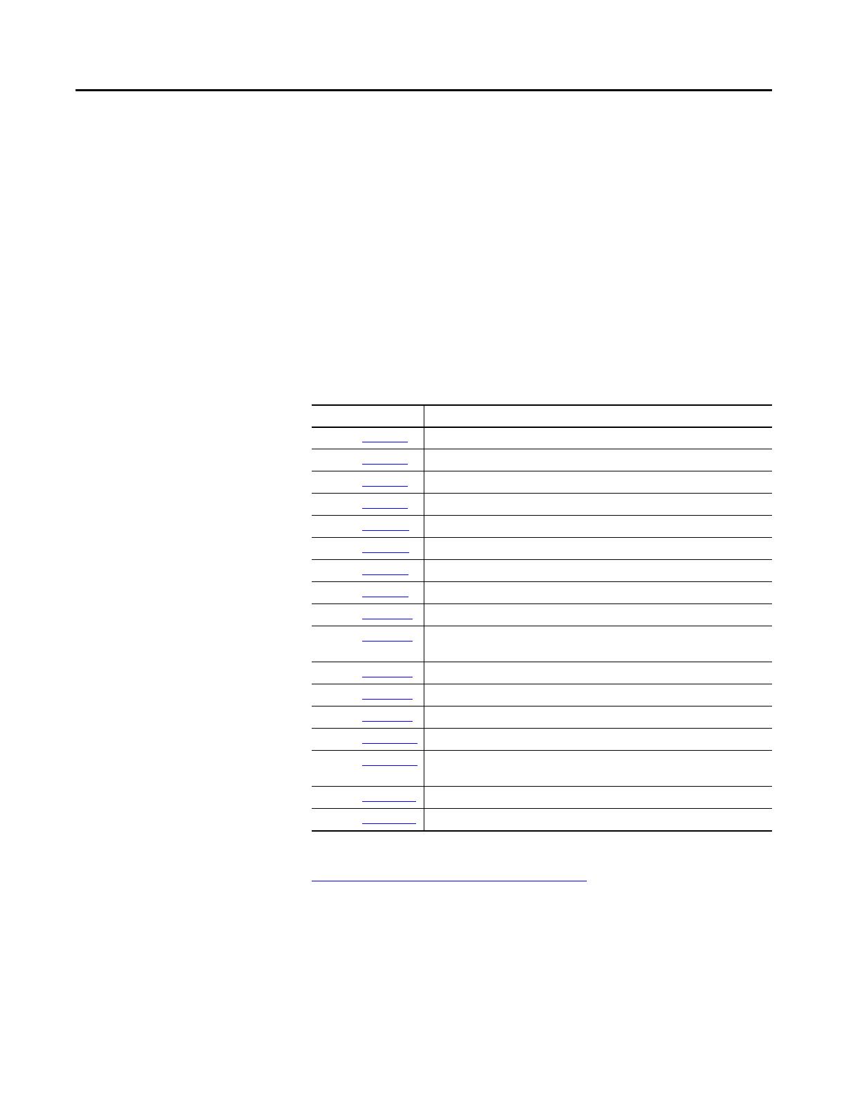
Additional Resources
These documents contain additional information concerning related products
from Rockwell Automation.
You can view or download publications at
http:/www.rockwellautomation.com/literature/
. To order paper copies of
technical documentation, contact your local Allen-Bradley distributor or
Rockwell Automation sales representative.
Resource Description
Publication 7000-IN006 PowerFlex 7000 Medium Voltage AC Drive (B Frame) Commissioning - ForGe Control
Publication 7000-IN007
PowerFlex 7000 Medium Voltage AC Drive (B Frame) Installation - ForGe Control
Publication 7000-IN008 PowerFlex 7000 Medium Voltage AC Drive (B Frame) Trans. & Handling - ForGe Control
Publication 7000-IN010 Handling, Inspection, and Storage of Medium Voltage Line Filter Capacitors
Publication 7000-PP002
PowerFlex 7000 Air-Cooled Drives
Publication 7000-QS002 HMI Interface Board Software Updater and Firmware Download Procedure
Publication 7000-TD001 PowerFlex 7000 Medium Voltage AC Drive (Firmware Version 6.xxx) - Classic Control
Publication 7000-TD002
PowerFlex 7000 Medium Voltage AC Drive (Firmware Version 9.xxx) - ForGe Control
Publication 7000-UM150 PowerFlex 7000 Medium Voltage AC Drive (B Frame) - Classic Control
Publication 7000-UM151 PowerFlex 7000 Medium Voltage AC Drive (B Frame) - ForGe Control (Using
PanelView 500)
Publication 7000-UM201
PowerFlex 7000 HMI Offering with Enhanced Functionality
Publication 7000-UM202 PowerFlex 7000 Medium Voltage AC Drive (B Frame) - ForGe Control
Publication 7000-UM203
PowerFlex 7000 Series Safe Torque Off
Publication 7000A-UM150
PowerFlex 7000 Medium Voltage AC Drive (A Frame) - Classic Control
Publication 7000A-UM151 PowerFlex 7000 Medium Voltage AC Drive (A Frame) - ForGe Control (Using
PanelView 550)
Publication 7000L-UM301
PowerFlex 7000 Medium Voltage AC Drive (C Frame) - ForGe Control
Publication 7000L-UM302 PowerFlex 7000 Medium Voltage AC Drive (C Frame) - ForGe Control (Marine)

8 Rockwell Automation Publication 7000-TG002J-EN-P - March 2015
Preface
Acronyms and Abbreviations
Acronym/ Abbreviation Description
A/D Analog/Digital
A2D Analog to Digital
AC Alternating Current
ACB Analog Control Board
Accel Acceleration
ADC Analog to Digital Converter
Anlg Analog
BW Bandwidth
Cap Capacitor
Ch Channel
Chn Channel
CIB Customer Interface Board
CMC Common Mode Choke
Cmd Command
Conv Converter
CT Current Transformer
Ctctr Contactor
Cur Current
DAC Digital to Analog Converter
DB Dynamic Braking
DC Direct Current
DCB Drive Control Board
DCSL Drive Control and Synchronization Link
DD Dimensional Drawings
Decel Deceleration
DIM Drive Identity Module
Dly Delay
DO Drive Output
DPI Drive Peripheral Interface
DPM Drive Processor Module
DrvIn Drive Input
ED Electrical Drawings
ESP Electric Submersible Pump
Fbk Feedback
Flt Fault
Fltr Filter
FO Fiber-Optic
FOB Fiber-Optic Interface Board
FOI Fiber-Optic Interface
FPGA Field-Programmable Gate Array

Rockwell Automation Publication 7000-TG002J-EN-P - March 2015 9
Preface
Freq Frequency
GND Ground
Gnrl General
HECS Hall Effect Current Sensor
Hi High
HP Horse Power
HW Hardware
I Current
IGDPS Isolated Gate Driver Power Supply
Init Initialize
Inv Inverter
IO Input/Output
Isoltn Sw Isolation Switch
L Inductance
L Line
LED Light-emitting diode
Liq Liquid
Lo Low
LR Line Reactor
LV Low Voltage
M Machine
Magntz Magnetizing
Max Maximum
Min Minimum
Mstr Master
MTR Motor
NVRAM Non-Volatile Random Access Memory
OC Overcurrent
OL Overload
OP Output
OT Overtemperature
OV Overvoltage
PD Parallel Drive
PF Power Factor
PFC Power Factor Correction
PID Proportional, Integral, Derivative (process control)
PLC Programmable Logic Control
PSD Power Structure Diagnostic
PWM Pulse-Width Modulation
Rect Rectifier
Acronym/ Abbreviation Description

10 Rockwell Automation Publication 7000-TG002J-EN-P - March 2015
Preface
Rot’n Rotation
SCB Signal Conditioning Board
SCR Silicon-Controlled Rectifier
SGCT Symmetrical-Gate Commutated Thyristor
Slv Slave
Spd Speed
SPGD Self-Powered Gate Driver
STO Safe Torque Off
SW Software
Sync Synchronous
Tach Tachometer
TFB Temperature Feedback Board
TFB3 Temperature Feedback Board, 3
rd
generation
Trp Trip
Trq Torq ue
TSN Transient Suppression Network
UB Unbalance
UPS Uninterrupted Power Supply
USART Universal Synchronous/Asynchronous Transmitter/Receiver
V Volt
VSB Volt Sensing Board
Wrn Warning
Xfer Tran sfer
XIO External Input/Output
Acronym/ Abbreviation Description

Rockwell Automation Publication 7000-TG002J-EN-P - March 2015 11
Chapter 1
Fault Messages
Overview
All faults, warnings, or messages displayed on the operator interface should be
thoroughly documented by the user prior to resetting those messages. This will
assist maintenance personnel in correcting problems and ensuring they do not
recur.
ATTENTION: Investigate all faults before resetting the drive.
Resetting the drive into a fault condition that has been unresolved can
propagate the faults and cause an increased level of damage to the equipment.

12 Rockwell Automation Publication 7000-TG002J-EN-P - March 2015
Chapter 1 Fault Messages
Fault Messages
All Drive Types
PF7000A
PF7000B
PF7000C
Marine Drive
Heat pipe Drive
Fault Message Fault Code Description Recommended Action(s)
X AC/DC#1 AC Fail 58 There can be up to 4 AC/DC power supplies in a drive,
designated 1, 2, 3 and 4. Each power supply will have its input
control voltage measured and monitored for reliable drive
operation. An AC Fail is detected when the input to any of the
AC/DC power supplies goes below 85Vrms.
120Vac is measured directly on the ACB at terminals J1 14-15.
The drive displays the measured value in the Metering group
parameters 118, 77, 79, and 92 for power supplies 1 to 4
respectively.
• Verify the input AC voltage to the power supply, typically 110Vac or 120Vac.
• Be sure that the AC/DC power supply monitor signal is connected to the ACB.
• Check the Metering group in the drive variables to view the control power value the drive
is measuring.
• The example below shows that the drive is detecting a single AC/DC power supply whose
input voltage is 116.6V.
X AC/DC#2 AC Fail 59
X AC/DC#3 AC Fail 60
X AC/DC#4 AC Fail 61
X AC/DC#1 DC Fail 48 There can be up to 4 AC/DC power supplies in a drive,
designated 1, 2, 3 and 4. Each power supply has its own
sensing circuit and will monitor its DC output voltage. The
AC/DC power supply triggers a DC Fail signal when an output
drops below 49Vdc.
The drive monitors the DC Fail signals from the inputs
connected to terminals J18, J19, J20 and J21.
The drive monitors the 56VDC supply via connection J15 1-2
on the ACB.
• Verify that the power supply is energized and is using the appropriate input control power.
• Measure the output voltage and confirm whether the output level is below the trip level.
• Verify that the fault detection wiring is per the drawings, and measure the voltage on the
trip signals. For example, Terminal J18 2-3 is 5Vdc when healthy, and 0V in a faulted state.
• Verify that the power supply internal cooling fan is operational, cycle control power if
needed.
• If the cooling fan is not operational, replace the power supply.
• Check parameter 121 in the Metering group of the drive variables to view the measured
DC voltage.
X AC/DC#2 DC Fail 49
X AC/DC#3 DC Fail 50
X AC/DC#4 DC Fail 51
X Adapter 1 Loss 17 There has been a loss of communication between the Drive
Processor Module (DPM) and the DPI adapter 1-6.
• Cycle control power to the drive.
• Change the adapter and/or DPM if all attempts to restore communication fail.
• Ensure that the adapter is plugged into the ACB, powered, and working properly.
X Adapter 2 Loss 18
X Adapter 3 Loss 19
X Adapter 4 Loss 20
X Adapter 5 Loss 21
X Adapter 6 Loss 22

Rockwell Automation Publication 7000-TG002J-EN-P - March 2015 13
Fault Messages Chapter 1
X Adaptr1 ForceFlt 26 There has been a loss of communication between the
identified DPI adapter and the customer’s communication
network. The communication between the drive and the DPI
adapter may still be active. This is a requirement for DPI
communications. If the loss of communication from the
network to the adapter is required to be a warning, this must
be set in the adapter itself, not within the drive.
• Verify the customer network is properly communicating with the device.
• Check DPM status LEDs and compare to the information in the User Manual.
• Change the adapter if all attempts to restore communication fail.
• Cycle control power.
X Adaptr2 ForceFlt 27
X Adaptr3 ForceFlt 28
X Adaptr4 ForceFlt 29
X Adaptr5 ForceFlt 30
X Adaptr6 ForceFlt 31
Ambient OvrTemp 182 NOT ACTIVE
Ambient LowTemp 183 NOT ACTIVE
Ambient FbrOptic 184 NOT ACTIVE
Ambient Sensor 185 NOT ACTIVE
X Arbitration Loss 602 The number of Arbitration Loss faults has exceeded the
maximum allowable level.
• Check the DCSL communication wiring and shielding.
X Auxiliary Prot’n 37 Standard External Fault/Warning Input included to allow the
end user to install a protective relay/system status contact
that can activate a drive fault or warning, depending on
configuration of Aux Prot Class (P445). The message means
that the drive has detected a fault triggered by the input
wired in the auxiliary input of the XIO card.
• Check the device responsible for the auxiliary contact to this input, and investigate the
cause of the open contact status.
• Check the 120V signal through the external device.
• Check the XIO board inputs and parameter status bits.
• Check the 120V wiring and the XIO card.
X Bypass CtctrOpen 168 The bypass contactor was opened without a command from
the drive. Verify the contactor feedback and the 120V wiring
to the ACB.
• Because the drive system needs to have complete control over all contactors, investigation
of the specific contactor fault is required.
• Verify contactor feedback.
• Verify the control power circuit for the contactor.
• Check permissive string to the contactor control relay (refer to drawing).
• Check contactor/breaker for physical malfunction (auxiliaries).
• Check ACB inputs and outputs at J1.
X Bypass IsoSwClsd 175 The bypass isolation switch is closed when it was expected to
be open. Verify the isolation switch mechanical set up and the
120V wiring to the ACB. Depending on the operating mode of
the drive, ensure that the switch is in the proper position.
• Depending on the mode of operation (Normal, System Test, Open-Circuit Test, DC Current
Test, or Open-Loop), there are specific states for all the possible system isolation switches
(Refer to the description of parameter 141 Hardware Options1. Be sure the isolation switches
are in the proper position.
• Verify wiring feedback.
• Verify isolation switch mechanical auxiliary setup.
• READ ASSOCIATED DESCRIPTION.
X Bypass IsoSwOpen 172 The bypass isolation switch is open when it was expected to
be closed. Verify the isolation switch mechanical set up and
the 120V wiring to the ACB. Depending on the operating
mode of the drive, ensure that the switch is in the proper
position.
All Drive Types
PF7000A
PF7000B
PF7000C
Marine Drive
Heat pipe Drive
Fault Message Fault Code Description Recommended Action(s)

14 Rockwell Automation Publication 7000-TG002J-EN-P - March 2015
Chapter 1 Fault Messages
X X CabinetTemp High
(C-Frame Only)
70 The drive has a temperature switch in several cabinets, and all
the N/C switches are connected in series and fed back to the
XIO input. The levels are set differently for different cabinets.
• Identify which switch has opened, and focus on that cabinet.
• Check for proper air flow within the identified section.
• Verify that the stirring fans are operating correctly.
• Verify that the ambient temperature is within tolerances.
X Capability Limit 465 The motor current exceeded maximum allowable level for the
variable torque drive. Drive was limiting the motor current to
the safe level for drive thermal protection, but new speed
operating point cannot be achieved higher than 6 Hz.
• Ensure that the drive is not used for constant torque load condition.
X CMC Blcked Exhst 477 There is possibly blockage to the CMC exhaust/inlet airflow.
Note: This fault word is used exclusively on Heatpipe drives.
• Ensure that there are no obstructions to the path of the outgoing/incoming air flow.
• Check for cooling fan deterioration.
• Verify if the trip setting (P813/P814) matched factory recommended value.
X CMC Blcked Inlet 480 There is possibly blockage to the CMC exhaust/inlet airflow.
Note: This fault word is used exclusively on Heatpipe drives.
• Ensure that there are no obstructions to the path of the outgoing/incoming air flow.
• Check for cooling fan deterioration.
• Verify if the trip setting (P813/P814) matched factory recommended value.
X CMC Double Fans 474 The drive has just lost two or more of the cooling fans. • Verify the fan contactors, fan overload and the 120V wiring to the XIO card.
X Cnv Airflow Loss 505 The cooling airflow velocity on the specified power stack is
below the trip/warn level.
• Ensure that there are no obstructions to the path of the outgoing/incoming air flow.
• Check for cooling fan deterioration. Verify if the trip (P840) and warn setting (P841)
matched factory recommended values.
X Cnv Double Fans 473 The drive has just lost two or more of the cooling fans. • Verify the fan contactors, fan overload and the 120V wiring to the XIO card.
X CMC Fan9 Ctctr 487 Loss of the cooling fan. • Verify the fan contactor, fan overload and the 120V wiring to the XIO card.
XCnv Fan3 Ctctr 482
XCnv Fan4 Ctctr 483
XCnv Fan5 Ctctr 484
XCnv Fan6 Ctctr 485
XCnv Fan7 Ctctr 486
X Control Pwr Loss 57 There has been a loss or dip in the control power feeding the
drive for more than 5 cycles.
• Ensure that the power source is active and investigate the reliability of the source.
• Check control power input to ACB.
All Drive Types
PF7000A
PF7000B
PF7000C
Marine Drive
Heat pipe Drive
Fault Message Fault Code Description Recommended Action(s)

Rockwell Automation Publication 7000-TG002J-EN-P - March 2015 15
Fault Messages Chapter 1
X X X Convrtr Air Flow 176 The air pressure drop at the input to the converter section
sensed by the pressure transducer (as a voltage) has dropped
below the value set in AirLoPresure Trp (P319). This is
dependent on the operation of the main cooling fan.
Components to check are cooling fan, air pressure transducer,
analog control board, blocked air filters, correct parameter
settings.
• Verify fan rotation, necessary air pressure is developed only with the correct direction of
fan rotation.
• Check for blocked airflow in the filters/heatsinks/ducting (if installed). Clean as necessary.
• Improper Trip settings – Verify pressure value voltage level when running with clear air flow,
and compare to expected values for that specific drive type.
• Verify the alarm and trip set-up procedure was completed adequately during
commissioning and adjust as necessary; applicable parameters are:
– Air Pressure Nom (P317)
– AirLoPresure Wrn (320)
– AirLoPresure Trp (319)
• Check that the pressure sensor is working and is connected to the ACB at J9. Control Voltage
for the pressure transducer is +15V on J9 terminals 1 to 3
• Confirm output of the transducer is stable, J9 terminal 2 to 3
• Verify for drives with external ducting that there is sufficient air to the drive input.
• Applicable Tech Notes:
– PowerFlex 7000-Gen-11 PowerFlex 7000 Air Pressure Sensor Setup
– PowerFlex 7000_4Gen_Gen-16 How to Configure Differential Pressure Transducer
– PowerFlex 7000-4Gen_Gen-23 High Air Pressure Fault When Upgrading Firmware to
Rev 8 or Higher
X X ConductivityHigh
(C-Frame Only)
OIBBS
68 The measured coolant conductivity is greater than 2 S/cm
3
. • Verify that no foreign debris has entered the system (iron piping, non-deionized water,
etc.).
• Wash the mesh filters.
• Change the de-ionizing cartridge and run the system, verifying that the conductivity is
decreasing.
• If the cooling pumps have not been running for a period of time, the conductivity level will
increase. Anticipate this and run the cooling pumps to reduce the conductivity level before
starting
X Config Fault Inv 629 Inverter configuration fault
: A functional safety hardware /
configuration mismatch was detected. There is a hardware
configuration fault on the inverter side.
• If the drive uses the STO feature, ensure no SPS jumper is installed on the inverter OIBBS.
• Verify the drive settings. If the drive uses the STO feature, enable STO.
• Verify the inverter OIBBS (for STO drive) or OIBB (for non-STO drive). In case of incorrect
part(s), contact the manufacturer for replacement spare parts.
X Config Fault Rec 625 Rectifier configuration fault: A functional safety hardware /
configuration mismatch was detected. There is a hardware
configuration fault on the rectifier side.
• If the drive uses STO feature, the SPS jumper on the rectifier OIBBS must be set correctly.
See parameter 274.
• Verify the drive settings. If the drive uses the STO feature, enable STO.
• Verify the rectifier OIBBS (for STO drive) or OIBB (for non-STO drive). In case of incorrect
part(s), contact the manufacturer for replacement spare parts.
X Config Fault1 616 Configuration Fault 1: This bit indicates that a configuration
conflict has been detected. The Safe Torque Off function is
incompatible with the following features: N+1, Parallel
Drives, 18-Pulse rectifiers.
• See parameters P141 for redundant devices, P153 for rectifier type, and P717 and P745 for
parallel drives.
• Verify the drive settings and disable the un-supported features.
• Cycle the control power.
X Config Fault2 617 Configuration Fault 2
: This bit indicates that a configuration
conflict has been detected. The Safe Torque Off function is
incompatible with drives utilizing a bypass contactor
including synchronous transfer.
• See parameters P99 for sync transfer enabled and P141 for bypass contactor
configuration.
• Verify the drive settings and disable the un-supported features.
• Cycle the control power.
All Drive Types
PF7000A
PF7000B
PF7000C
Marine Drive
Heat pipe Drive
Fault Message Fault Code Description Recommended Action(s)

16 Rockwell Automation Publication 7000-TG002J-EN-P - March 2015
Chapter 1 Fault Messages
X Control 5V Loss 54 There is a single DC/DC power in each drive. It receives 56VDC
input and produces various levels of DC voltages on the
output. One of these output voltage level is 5Vdc. It is a critical
voltage level for the drive processors. This fault message
indicates the 5Vdc produced by the DC/DC power supply has
failed. The drive monitors the 5Vdc by measuring this
voltage.The 5Vdc is connected to the ACB terminal JX 1-2.
• Check connections, test the rail voltage level and test for shorts.
• Replace the DC/DC converter if this problem remains.
X Control 15V Loss 55 There has been a loss of the 15 volt DC rail from the DC/DC
converter.
• Check connections, test the rail voltage level and test for shorts.
• Replace the DC/DC converter if this problem remains.
X Control 56V Loss 52 The drive has detected a loss of the 56V dc voltage feeding the
DC/DC converter.
• Check the connections, feedback wiring on J14 of the ACB, the DC output of the AC/DC
converter and the input voltage to the DC/DC converter.
• Replace the power supply if required.
X X CoolantLevel Low
(C-Frame Only)
69 The measured coolant level within the reservoir has dropped
below the second (lowest) level sensor and the drive has
faulted. This sensor is set for the minimum level required to
ensure there will be no air drawn into the system through the
reservoir.
• Verify that the drive cooling system does not have any coolant leaks – repair if found.
• Add the proper amount of de-ionized water to get the level above the warning sensor (de-
ionized water will evaporate, not the glycol).
X X CoolantTemp High
(C-Frame Only)
67 The measured coolant temperature has exceeded 54 °C
(129 °F). The drive detected that the coolant temperature has
exceeded the trip setting in P483. Ensure that the heat
exchanger fans are working properly and the room ambient is
adequate for the drive operation.
• Verify the heat exchanger fans are operating.
• Verify that the thermostatic valve is fully opened.
• Check that all valves are in the normal operating position.
• Verify that the drive is operating within specified load and ambient conditions.
X X CoolantTemp Low
(C-Frame Only)
66 The measured coolant temperature has dropped below 4 °C
(40 °F). It will not clear until the coolant temperature reaches
10 °C (50 °F). This fault will only occur if the drive is not
running, to stop you from starting with a low coolant
temperature. If you are already running when the coolant
level drops, you will only get a warning.
• Verify that the thermostatic bypass valve (V10) was not left open.
• Verify that the ambient temperature within the drive control room is not below
specification.
• Warm up the control room ambient to get the drive to an operational level.
X CRC Fault 601 The number of Cyclic Redundancy Check (CRC) faults has
exceeded the maximum allowable level.
• Check the DCSL communication wiring and shielding.
All Drive Types
PF7000A
PF7000B
PF7000C
Marine Drive
Heat pipe Drive
Fault Message Fault Code Description Recommended Action(s)

Rockwell Automation Publication 7000-TG002J-EN-P - March 2015 17
Fault Messages Chapter 1
X Current Sensor 155 This fault is detected in either DC test mode or open loop test
mode or during auto tune. This indicates that there is a
problem with the current feedback in the drive. There are
three different current sensors: Line side CT, DC Link HECS and
Motor HECS. To ascertain the cause of the fault check
Cur Sens FltCode (P764) under Diagnostic group.
Corresponding bit and its troubleshooting guide should be
followed.
• If you have the Line HECS/CT code, the line current measurement is not what is expected
at this level of dc current. Either of the CT DC HECS and there burden resistors may be
damaged or programmed incorrectly. For example, the DC HECS may actually be 2500:1,
the drawings and parameters indicate 4000:1. Another cause would be an unplugged DC
HECS.
• If you have the CT Phs Seqn code, the CTs are likely swapped. For example, the CT/wiring
for 2U has been switched with 2W.
• If you have the CT Phs/Alpha code, the rectifier is firing with the wrong firing angle
relative to the angle measured from the line current. This can occur when the CTs on an
18-pulse rectifier are switched between master and slaves.
• If you have the Cap/CT Error code, this only occurs for PWM rectifiers when energized and
not running. The line current measured by the CTs does not match the expected line current
based on the capacitor parameters and measured voltage. Possible causes are incorrect
capacitor, CT or burden resistor parameters, and in some cases, blown TSN fuses.
• If you have the Motor HECS code, this only occurs when running on the motor in open
loop mode. The drive compares the motor current to the dc current, and flags this fault if
there is a significant difference. If there were no Line HECS/CT codes, then the likely cause of
this fault in an incorrectly programmed motor HECS value or burden resistor. Other causes
could be a defective or unplugged motor HECS.
• Make sure hardware parameters are correct and do not exceed the range.
X DAN Comm Loss 456 This is applicable to parallel drive systems. Drive Area
Network (DAN) communication fault. The communication
between drives used in a parallel drive system communicates
over the DAN link. This fault indicates a loss of the DAN link for
a drive acting as a Slave. This would result in the slave drive
stopping.
• Check RS485/RS232 converter. Red LED should be steady, and green and yellow transmit
and receive LEDs should be flashing.
• Check RS485 cable between drives.
• Check RS232 cable between ACB board and serial converter.
• Previous issue required the replacement of the RS232 to RS485 converter (MOXA)
All Drive Types
PF7000A
PF7000B
PF7000C
Marine Drive
Heat pipe Drive
Fault Message Fault Code Description Recommended Action(s)

18 Rockwell Automation Publication 7000-TG002J-EN-P - March 2015
Chapter 1 Fault Messages
X DBSE1DiagFbkLoss 520 This is an offline Symmetrical Gate Commutated Thyristors
(SGCT) fault on the DB side and indicates that the drive did
not sense the proper diagnostic feedback before and after the
diagnostic gating. It is likely that the feedback fiber-optic
cable is not plugged in or has been damaged.
• Check that the fiber-optic cables are seated properly in the optical interface board and the
SGCT firing card.
• Check that the fiber-optic cable is not pinched or damaged.
• Complete a resistance check per the instructions in the manual.
• NOTE: SGCTs may not have completely shorted, and still could read in the k range – Any
devices with low suspect readings should be changed.
• Check the LED status of the SGCT gate driver card for abnormal readings.
• Complete a Gating Test mode check on the devices.
• Verify the associated 20V power supply is powered and active.
• Verify all the power connections to the SGCT firing card are seated properly.
XDBSE2DiagFbkLoss521
XDBSE3DiagFbkLoss522
XDBSE4DiagFbkLoss523
XDBSH1DiagFbkLoss524
XDBSH2DiagFbkLoss525
XDBSH3DiagFbkLoss526
XDBSH4DiagFbkLoss527
X DBSE1GatingLoss 528
X DBSE2GatingLoss 529
X DBSE3GatingLoss 530
X DBSE4GatingLoss 531
X DBSH1GatingLoss 532
X DBSH2GatingLoss 533
X DBSH3GatingLoss 534
X DBSH4GatingLoss 535
X DBSE1Offline 536 This SGCT device on the DB side was detected to be faulted
after the input contactor was closed or following a start
command or following a drive reset. After isolating the drive
from MV, ensure that the device, IGDPS power supply and the
fiber-optic signals are not damaged.
• Complete a resistance check per the instructions in the manual.
• NOTE: SGCTs may not have completely shorted, and still could read in the k range – Any
devices with low suspect readings should be changed.
• Check the LED status of the SGCT gate driver card for abnormal readings.
• Complete a Gating Test mode check on the devices.
• Verify the associated 20V power supply is powered and active.
• Verify all the power connections to the SGCT firing card are seated properly.
XDBSE2Offline537
XDBSE3Offline538
XDBSE4Offline539
X DBSH1Offline 540
X DBSH2Offline 541
X DBSH3Offline 542
X DBSH4Offline 543
All Drive Types
PF7000A
PF7000B
PF7000C
Marine Drive
Heat pipe Drive
Fault Message Fault Code Description Recommended Action(s)

Rockwell Automation Publication 7000-TG002J-EN-P - March 2015 19
Fault Messages Chapter 1
X DBSE1Online 544 The drive detected that the diagnostic feedback from this
SGCT device on the DB side did not match the gating pattern.
After isolating the drive from MV, ensure that the device,
IGDPS power supply and the fiber-optic signals are not
damaged.
• Complete a resistance check per the instructions in the manual.
• NOTE: SGCTs may not have completely shorted, and still could read in the k range – Any
devices with low suspect readings should be changed.
• Check the LED status of the SGCT gate driver card for abnormal readings.
• Complete a Gating Test mode check on the devices.
• Verify the associated 20V power supply is powered and active.
• Verify all the power connections to the SGCT firing card are seated properly.
• For nuisance faults, contact the factory about extending the Diagnostic Delay.
XDBSE2Online545
XDBSE3Online546
XDBSE4Online547
X DBSH1Online 548
X DBSH2Online 549
X DBSH3Online 550
X DBSH4Online 551
X DB Airflow Fault 570 The drive has detected that either the DB exhaust
temperature or the DB ambient temperature has exceeded
the corresponding trip level. For the DB Airflow Fault the drive
has detected that the airflow in the DB cabinet is below the
trip level.
• Verify the trip and warning settings match the factory recommended values.
• Check TFB, temperature sensors and airflow sensor in DB cabinet.
• Verify that feedback values are consistent with actual conditions.
• Ensure that ambient conditions do not exceed specifications.
XDB Amient
OvrTemp
569
X DB Resis OvrTemp 568
X DB Airflow Sensor 573 DB airflow sensor not functioning. A warning is issued if this
happens while running and a fault is issued when the drive is
stopped.
• Check TFB and airflow sensor in the DB cabinet.
• Verify that feedback value is consistent with actual conditions.
X DB AmbientSensor 572 DB temperature sensor not functioning. For DB Resis Sensor, a
warning is issued if this happens while running and a fault is
issued when the drive is stopped.
• Check TFB (onboard ambient sensor) and DB exhaust temperature sensor in the DB
cabinet.
• Verify that feedback values are consistent with actual conditions.
X DB Resis Sensor 571
X DB fiber-optic 574 DB TFB is not functioning. • Check TFB in the DB cabinet.
• Verify that feedback values are consistent with actual conditions.
X DBR Overload 575 Braking energy dissipated in DB Resistor exceeded the fault
threshold (i.e. 150% of DBR rated energy). This is a calculated
measurement and does not reflect any physical feedback.
• Verify DBR parameter settings are correct.
• Verify DC Current feedback measurement is correct.
X DC Link Flow Low
(C-Frame Only)
72 The flow switch in the DC Link coolant path has detected the
flow is less than optimal, indicating a problem with the flow
path. This is not designed to specifically measure flow. This is
a switch that differentiates between flow and no flow.
• Verify pressure values in the cooling system are nominal.
• Verify the cooling path is not restricted because of tube crimping.
• Check flow switch for proper operation.
• It may be required to disconnect cooling path and complete a check on the DC Link for
blockages.
All Drive Types
PF7000A
PF7000B
PF7000C
Marine Drive
Heat pipe Drive
Fault Message Fault Code Description Recommended Action(s)

20 Rockwell Automation Publication 7000-TG002J-EN-P - March 2015
Chapter 1 Fault Messages
X DClnk OvrCurrent 113 The DC Link current given by Idc Feedback (P322) has
exceeded the DC Link current trip settings (P169). Verify the
parameter settings of the drive. Check the HECS and burden
resistor. Confirm stable operation of the drive and any sudden
load transients.
• Verify that the parameters for drive and device ratings, and installed current sensing
components are set accordingly.
• Verify that the DC Link HECS is wired properly and properly powered.
• Verify the burden resistor value.
• Complete a DC Current Test to verify the feedback corresponds to the IDC command.
• Setup trending to capture DC Link current feedback and other related read-only
parameters (Contact factory if you require assistance).
• Check Alpha Line, and verify that the value is not too low (15°) and the current regulator is
not in limit; Decrease Flux Command Base Speed or increase incoming Line Voltage.
• Restart the drive to allow the start up diagnostics to detect any shorted thyristors, but
only attempt this once if shorted SCRs are detected.
X DCLnk OvrTemp 34 The thermal switch in the DC Link inductor has detected an
over temperature condition and opened the AC input to the
standard XIO. Ensure that the converter cooling fan is working
and that the air flow is not obstructed. Also check the 120V
wiring and the XIO card. There is a thermal switch in each DC
Link winding, and they are connected in series.
• Verify operating conditions (ambient/ altitude/ load levels/ ventilation and fans) and
verify that the DC Link Reactor is within ratings.
• Check the 120V signal through the thermal switch.
• Verify the drive cooling circuit is operating correctly.
• Check the XIO board inputs and parameter status bits.
• Determine through elimination whether there is a faulty switch and replace if necessary.
X DC Neutral VSB 461 This fault indicates that the voltage sensing board associated
with the dc and neutral voltages is not plugged in.
• Check connector J25.
• Verify connection from VSB to ACB.
X X DriveApplication 583 This fault indicates that either the drive application (P751)
has been changed or that one or more of the application-
specific functions are incorrectly set (for example, for Marine
Application 1, P751 Drv Application must be set to ‘Marine 1’,
Speed Ref Select (P7) must be set to ‘App Specific’,
TorqueRef Select (P401) must be set to ‘App Specific’ and
Trq Control Mode (P90) must be set to ‘App Control’).
• Ensure that all application-specific parameters are correctly set.
• Cycle control power.
X Drive OvrLoad 144 Drv OvrLoad Trp (P163) as the absolute trip level,
Drv OvrLoad Dly (P164) as the base trip delay, and
Drv OvrLoad Min (P269) as initial detection level.
The drive has detected an overload condition in the dc link
indicated by Drv Overload (P551).
• Transient Loading – Check torque limit and overload settings and compare loading to
torque settings and trip settings.
• Open Burden Resistor – Check Current feedback and check the burden resistors.
• Verify the drive sizing and that the overload parameters to meet the load requirements.
DvcAnodCath/Snub 154 Device Anode-Cathode or Snubber fault NOT USED
Drv Output Open 161 NOT USED NOT USED
X Duplct Node Flt 603 The drive has detected nodes that have the same Node ID. • Change the affected drive(s) node ID using parameter DCSL Node ID (935).
X Encoder Loss 163 • Be sure that the encoder is powered and connected properly.
• Be sure that all channels are connected properly and not swapped at motor and drive end.
For example, swapping A+ and A- will give this fault
• Z+ and Z- are not to be used in PF7000 Forge drives, remove any wires, jumpers on the Z+
Z- terminals
• Tech notes related to Encoders are PF7000 4th Gen_FMW-11, PF7000 Firmware 9.001 and
9.002 with Encoder Release Notes
All Drive Types
PF7000A
PF7000B
PF7000C
Marine Drive
Heat pipe Drive
Fault Message Fault Code Description Recommended Action(s)
/