KVH TracPhone F55 Installation guide
- Category
- Television antennas
- Type
- Installation guide
This manual is also suitable for

A Guide to the TracPhone F55 & F77
Satellite Communications
KVH TracPhone
®
F55 & F77
installation
manual

Installation Notes
Before you install your TracPhone
®
F55/F77 system, please read the important notes
below.
PLEASE READ!
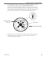
Important Notice About Your Data Connection
To prevent inadvertent airtime usage, the user must disconnect the
data connection when not in use. If the data connection is not
properly disconnected, your computer may dial out on its own,
which could result in an unintended airtime charge.
KVH accepts no responsibility if this occurs. It is the vessel
owner’s responsibility to ensure that the TracPhone F55/F77 is
correctly interfaced with the vessel’s computer.
If you have any questions about data connections, please contact
KVH Technical Support.
TracPhone F55/F77 Installation Notes
11
34-0004 Rev. C

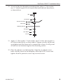
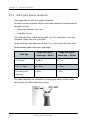
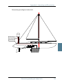
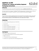
Antenna Mounting Instructions
To mount the KVH TracPhone F55/F77 antenna, follow the
alternate instructions below. These special instructions supercede
the mounting information in Section 3 of the Installation Manual.
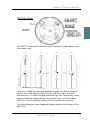
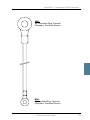
The TracPhone F55 is housed in a 26" (66 cm)-diameter dome. Follow the instructions
on the following page to mount the antenna.
The TracPhone F77 is housed in either a standard dome or a deluxe dome, both
measuring approximately 35" (89 cm) in diameter. If your antenna is housed in a
standard dome, follow the instructions in Section 3 of the Installation Manual to
mount the antenna. If your antenna is housed in a deluxe dome, skip to page 8 of
these installation notes to mount the antenna.
22
TracPhone F55
TracPhone F77
OR
Standard Dome Deluxe Dome

TracPhone F55/F77 Installation Notes
33
34-0004 Rev. C
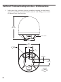
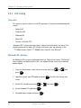
TracPhone F55 Antenna Mounting Instructions
To mount the KVH TracPhone F55 antenna, follow the alternate instructions below.
1. Make sure that you have chosen a suitable mounting location based
upon the guidelines provided in this manual and taking into account
the dimensions shown below.
27.36"
(695 mm)
4x .50"
(4x 13 mm)
Through Holes
for Mounting
26.2"
(665 mm)
12.0"
(305 mm)
6.0" (152 mm)
6.0" (152 mm)
12.0"
(305 mm)

44
2. Remove the antenna unit from its shipping carton and set the
radome aside in a safe place.
3. At the mounting site (or a stub mast’s mounting platform), lay out
the four mounting bolt holes and cable access hole as shown below.
The cable access hole must be located on the starboard side and
must measure at least 2" (50 mm) and no greater than 3
1
⁄2" (90 mm) in
diameter, large enough to access the antenna unit’s baseplate
connector.
4x 0.5"
(4x 13 mm)
26.2"
(665 mm)
12.0"
(305 mm)
6.0" (152 mm)
6.0" (152 mm)
12.0"
(305 mm)
DOME
5.0"
(127 mm)
2" Minimum
( 50 mm Minimum)
FWD
Antenna Baseplate Mounting Hole Pattern, Top View

TracPhone F55/F77 Installation Notes
55
34-0004 Rev. C
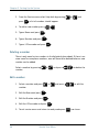
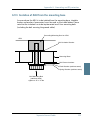
4. Before drilling the holes in the deck or mounting platform, you need
to verify that the antenna will be aligned properly when it is
mounted. Position the antenna baseplate assembly in place over the
hole locations, with the baseplate connector centered over the cable
access hole location. Ensure the baseplate’s “Forward” arrow (shown
below) points toward the bow. Set the antenna baseplate aside.
5. Drill the four
1
⁄2" (13 mm) bolt holes and cut out the cable access hole
(following the layout in Step 3). Smooth the edges of the cable
access hole to protect the cable.
Antenna Baseplate
Connector
Mounting Bolt
Hole (x4)

66
6. a. If mounting the antenna unit on a stub mast:
Position the foam seal on the mounting surface so that it is centered
between the four mounting holes and surrounding the platform’s
center hole. Clean the mounting surface where the foam seal will be
placed. Remove the paper backing from the foam seal to expose the
adhesive, then lay the foam seal in place, adhesive side down, and
press down firmly to bring the adhesive into full contact along the
bottom.
b. If mounting the antenna unit on a deck:
Position the foam seal on the mounting surface so that it is
surrounding the cable access hole. Clean the mounting surface
where the foam seal will be placed. Remove the paper backing from
the foam seal to expose the adhesive, then lay the foam seal in place,
adhesive side down, and press down firmly to bring the adhesive
into full contact along the bottom.
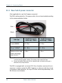
7. Bring the antenna cable from belowdecks up through the cable
access hole. Connect the antenna cable to the antenna’s baseplate
connector.
8.
If mounting the antenna unit on a stub mast:
After connecting the antenna cable, be sure to seal the connector
assembly to protect it from seawater and corrosion.
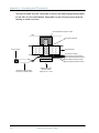
9. Place the antenna baseplate over the holes drilled in the mounting
surface, ensuring the baseplate’s “Forward” arrow is pointing
toward the bow.

10. At each of the four baseplate mounting holes, place a
3
⁄8" flat washer
on a
3
⁄8"-16 bolt (supplied in the kitpack) and insert the bolt from above,
as shown below.
11. Apply a
3
⁄8" flat washer,
3
⁄8" lock washer, and
3
⁄8"-16 hex nut (supplied in
the kitpack) from below, as shown above. Tighten securely (but do not
overtighten) until the foam seal is compressed as far as it will go and
all four feet are bottomed against the mounting surface.
12. Place the radome over the baseplate. Align the six radome screw
holes with the inserts in the baseplate, insert the #10-32 screws and
tighten. Install a protective screw cap over each screw.
TracPhone F55/F77 Installation Notes
77
34-0004 Rev. C
Bolt
Flat Washer
Antenna Unit Base
Foam Seal
Mounting Surface
Flat Washer
Hex Nut
Lock Washer

88
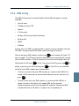
TracPhone F77 Antenna Mounting Instructions - KVH Deluxe Dome
1. Make sure that you have chosen a suitable mounting location based
upon the guidelines provided in this manual and taking into account
the dimensions shown below.
FWD
38.86"
(987 mm)
4x .50"
(4x 13 mm)
35"
( 889 mm)
12"
(305 mm)
6"
(152 mm)
6"
(152 mm)
12"
(305 mm)
Access Hatch
17"
(432 mm)

TracPhone F55/F77 Installation Notes
99
34-0004 Rev. C
2. Remove the antenna unit from its shipping carton.
3. At the mounting site, lay out the four mounting bolt holes as shown
below. Also, lay out a cable access hole large enough to
accommodate the antenna cable.
4. Before drilling the holes in the deck or mounting platform, you need
to verify that the antenna will be aligned properly when it is
mounted. Position the antenna unit in place over the hole locations
and ensure the baseplate connector is facing the stern. Set the
antenna unit aside.
FWD
4 x 0.5"
(4 x 13 mm)
12"
(305 mm)
6"
(152 mm)
12"
(305 mm)
6"
(152 mm)
Baseplate Footprint
17"
( 432 mm)
Antenna Baseplate Mounting Hole Pattern, Top View
Baseplate
Connector

1100
5. Drill the four
1
⁄2" (13 mm) bolt holes and cut out the cable access hole
(following the layout in Step 3). Smooth the edges of the cable
access hole to protect the cable.
6. Bring the antenna cable from belowdecks up through the cable access
hole. Connect the antenna cable to the antenna’s baseplate connector.
7. Place the rear logo plate over the cable, so that the cable exits the center
opening. Using the six M4 screws supplied in the kitpack, attach the logo
plate to the antenna baseplate as shown below.
8. Place the antenna unit over the holes drilled in the mounting
surface, ensuring the baseplate connector faces the stern.

9. At each of the four baseplate mounting holes, place an M10 lock
washer and flat washer on an M10 bolt (supplied in the kitpack) and
insert the bolt into the hole from below, as shown below. Tighten
securely (but do not overtighten) until the four feet are bottomed
against the mounting surface.
10. Install a protective screw cap over all eight radome screws.
TracPhone F55/F77 Installation Notes
1111
34-0004 Rev. C
M10 x 1.5 Hex-head Bolt
Antenna Unit Base
Mounting Surface
M10 Flat Washer
M10 Lock Washer

Thrane & Thrane A/S
TT-3086A Sailor Fleet55
TT-3084A Sailor Fleet77
Installation Manual
Document number: TT98-116875-E
Release date: March 15, 2007

Information in this document is subject to change without notice and does not represent
a commitment on the part of Thrane & Thrane A/S. It is recommended that the latest
version of the manual is downloaded from the Thrane Extra net or requested from the
distributor.
Copyright
© 2007 Thrane & Thrane A/S. All rights reserved. Printed in Denmark.
Trademark Acknowledgements
• Inmarsat is a registered trademark of the International Maritime Satellite
Organisation (IMSO) and is licensed by IMSO to Inmarsat Limited and Inmarsat
Ventures plc.
• Inmarsat’s product names are either trademarks or registered trademarks of
Inmarsat.
• Other product and company names mentioned in this manual may be trademarks or
trade names of their respective owners.
Company Addresses
www.thrane.com
Denmark Denmark
Thrane & Thrane A/S
Lundtoftegårdsvej 93 D
DK-2800 Kgs. Lyngby
Denmark
T: +45 39 55 88 00
F: +45 39 55 88 88
Thrane & Thrane Aalborg A/S
Porsvej 2
DK-9200 Aalborg SV
Denmark
T: +45 39 55 88 00
F: +45 96 34 61 01
USA China
Thrane & Thrane, Inc.
509 Viking Drive, Suites K, L and M
Virginia Beach, VA 23452
USA
T: +1 (757) 747-2341
F: +1 (757) 463-9581
Thrane & Thrane Shanghai
Representative Office
28J Pufa Tower
588 Pudong Rd(S), Pu Dong
200120 Shanghai
P. R. China
T: +86 21 68 87 87 80
F: +86 21 68 87 71 12

iii
Safety and Warranty 1
General
All cables for the Fleet55/77 system are shielded and should not be affected
by magnetic fields. However, if possible do not run cables parallel to AC
wiring – failing to do so might cause the equipment to be faulty or working
properly.
Service
User access to the interior of the BDU unit is prohibited. Service may only be
performed by a technician authorized by Thrane & Thrane A/S - failing to do
so will void the warranty. Access to the interior of the ADU is allowed, but
only for replacement of certain modules - as described in this manual.
General service may only be performed by a technician authorized by Thrane
& Thrane A/S - failing to do so may void the warranty.
Radar safety distance
Do not move the ADU closer to radars than the minimum safety distance
specified in this manual - this will possibly damage the ADU eventually.
Equipment must be installed with a minimum safe distance to magnetic
steering compass of at least 1.25 m. Personal safe distance is 4 m from the
F77 ADU and 2 m from the F55 ADU while it is transmitting.
Grounding, cables and connections
The BDU unit shall be connected to the ground of the ship via the Antenna
Pigtail Cable and the Grounding Kit (Accessories). Further, the BDU must be
grounded at its grounding stud.
The ADU shall be grounded to the ship via one or more of its mounting bolts.
The shielded cables must generally be grounded in both ends, except for the
cable between BDU and Cradle, which shall not be grounded in the Cradle
end.

iv
Connections of all types of equipment must be done while the unit is
switched off. For further grounding information read Appendix G Grounding
and RF protection on page 105.
Do not extend the cables beyond those specified for the equipment – except
from the cable between the BDU and ADU. The cable between the BDU and
ADU can be extended if it complies with the specified data concerning cable
losses etc.
Power supply
Operation voltage is 24 V DC. Note that long-term operation below 24 V DC
should be avoided.
It is recommended that the voltage is provided by the ship hot 24 V DC power
bus.
Be aware of high start-up peak current. 16 A@24 V, 15 ms.
Maximum operational peak power requirement for F77/F55 is 240/200 W
and maximum average power consumption is 180/150 W.
If a 24 V DC power bus is not available, an external 115/230 VAC to 24 V DC
power supply can be used.
Equipment ventilation
To ensure adequate cooling of the BDU a 5 cm unobstructed space must be
maintained around all sides of the unit (except the bottom side).
BDU ambient temperature range: -15° to +55°C.
Failure to comply with the rules listed above will void the warranty!

v
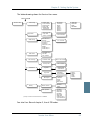
Table of Contents
Chapter 1 System Units
1.1 Introduction ............................................................... 1
1.2 Below Deck Unit – BDU .............................................. 1
1.3 Display Handset .........................................................2
1.4 Distress Cradle ...........................................................2
1.5 Passive Cradle ...........................................................2
1.6 Above Deck Unit – ADU ..............................................2
Chapter 2 GMDSS Installations
2.1 Requirements ............................................................3
2.2 Distress call initiation ................................................3
2.3 Maritime Safety Information ......................................3
2.4 Power Supply .............................................................4
Chapter 3 Placing the Antenna
3.1 Obstructions ..............................................................7
3.2 Radiation Hazard .......................................................8
3.3 Interference ...............................................................9
3.4 Antenna Mast Design ................................................14
Chapter 4 Installing the ADU
4.1 Unpacking ................................................................19
4.2 Preparation ...............................................................19
4.3 Grounding ................................................................19
4.4 ADU cables ..............................................................20

Table of Contents
vi
4.5 Mounting .................................................................22
4.6 Important notes .......................................................22
Chapter 5 Installing the BDU
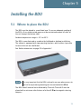
5.1 Where to place the BDU ..........................................23
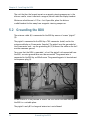
5.2 Grounding the BDU ..................................................24
Chapter 6 F77 Distress Cradle
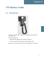
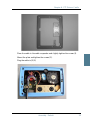
6.1 Introduction .............................................................27
6.2 Distress Cradle Assembly .........................................28
6.3 Assembly - Default ...................................................28
6.4 Assembly – Alternative ............................................. 31
Chapter 7 F55 Passive Cradle
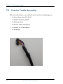
7.1 Introduction .............................................................33
7.2 Passive Cradle Assembly ..........................................34
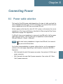
Chapter 8 Connecting Power
8.1 Power cable selection ..............................................37
8.2 Power supply specification ...................................... 41
Chapter 9 Setting Up the System
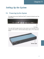
9.1 Powering Up the System ..........................................43
9.2 Powering Down the System ......................................44
9.3 Service User Menu ...................................................44
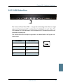
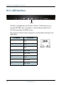
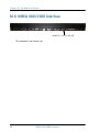
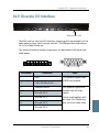
Chapter 10 Hardware Interfaces
10.1 Overview ..................................................................53

Table of Contents
vii
10.2 Analogue 2-wire Interface .......................................54
10.3 Cradle/Handset Interface .........................................55
10.4 ISDN Interface .........................................................56
10.5 USB Interface ........................................................... 57
10.6 LAN Interface ...........................................................58
10.7 RS-232 Interface ......................................................59
10.8 NMEA 0183/2000 Interface .......................................60
10.9 Discrete I/O interface ................................................61
Chapter 11 Service and Repair
11.1 Introduction .............................................................63
11.2 Modules .................................................................63
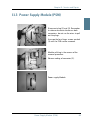
11.3 Power Supply Module (PSM) ....................................65
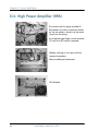
11.4 High Power Amplifier (HPA) .....................................66
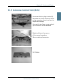
11.5 Antenna Control Unit (ACU) .....................................67
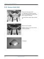
11.6 Sensor Unit (SU) ......................................................68
11.7 End Stop Switches (ESS) ..........................................69
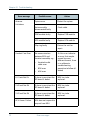
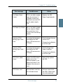
Chapter 12 Troubleshooting
12.1 Error messages .........................................................71
12.2 Handset Com Error troubleshooting procedure ........ 75
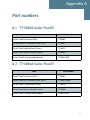
Appendix A Part numbers
A.1 TT-3086A Sailor Fleet55 ........................................... 77
A.2 TT-3084A Sailor Fleet77 ........................................... 77
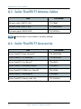
A.3 Sailor Fleet55/77 Antenna Cables ............................78

Table of Contents
viii
A.4 Sailor Fleet55/77 Accessories ...................................78
A.5 Optional Sailor Fleet55 Cradle Cables .......................79
A.6 Optional Sailor Fleet77 Cradle Cables .......................79
A.7 Optional Sailor Fleet55/77 Cradles & handsets .........79
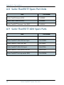
A.8 Sailor Fleet55/77 Spare Part Units ........................... 80
A.9 Sailor Fleet55/77 ADU Spare Parts .......................... 80
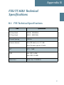
Appendix B F55/77 ADU Technical Specifications
B.1 F55 Technical Specifications ..................................... 81
B.2 F77 Technical Specifications .....................................83
B.3 F55/F77 Environmental Specifications ......................84
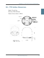
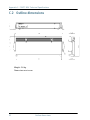
B.4 F55 Outline Dimensions .......................................... 85
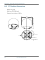
B.5 F77 Outline Dimensions ........................................... 86
B.6 Outline Dimensions, Flange .....................................87
Appendix C F55/77 BDU Technical Specifications
C.1 Technical specifications .......................................... 89
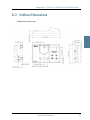
C.2 Outline dimensions ..................................................92
C.3 Measuring the Ship Source Impedance ....................93
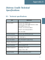
Appendix D Distress Cradle Technical Specifications
D.1 Technical specifications ...........................................95
D.2 Outline Dimensions ..................................................97
Appendix E Passive Cradle Technical Specifications
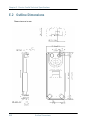
E.1 Technical Specifications .......................................... 99
E.2 Outline Dimensions ................................................ 100
Page is loading ...
Page is loading ...
Page is loading ...
Page is loading ...
Page is loading ...
Page is loading ...
Page is loading ...
Page is loading ...
Page is loading ...
Page is loading ...
Page is loading ...
Page is loading ...
Page is loading ...
Page is loading ...
Page is loading ...
Page is loading ...
Page is loading ...
Page is loading ...
Page is loading ...
Page is loading ...
Page is loading ...
Page is loading ...
Page is loading ...
Page is loading ...
Page is loading ...
Page is loading ...
Page is loading ...
Page is loading ...
Page is loading ...
Page is loading ...
Page is loading ...
Page is loading ...
Page is loading ...
Page is loading ...
Page is loading ...
Page is loading ...
Page is loading ...
Page is loading ...
Page is loading ...
Page is loading ...
Page is loading ...
Page is loading ...
Page is loading ...
Page is loading ...
Page is loading ...
Page is loading ...
Page is loading ...
Page is loading ...
Page is loading ...
Page is loading ...
Page is loading ...
Page is loading ...
Page is loading ...
Page is loading ...
Page is loading ...
Page is loading ...
Page is loading ...
Page is loading ...
Page is loading ...
Page is loading ...
Page is loading ...
Page is loading ...
Page is loading ...
Page is loading ...
Page is loading ...
Page is loading ...
Page is loading ...
Page is loading ...
Page is loading ...
Page is loading ...
Page is loading ...
Page is loading ...
Page is loading ...
Page is loading ...
Page is loading ...
Page is loading ...
Page is loading ...
Page is loading ...
Page is loading ...
Page is loading ...
Page is loading ...
Page is loading ...
Page is loading ...
Page is loading ...
Page is loading ...
Page is loading ...
Page is loading ...
Page is loading ...
Page is loading ...
Page is loading ...
Page is loading ...
Page is loading ...
Page is loading ...
Page is loading ...
Page is loading ...
Page is loading ...
Page is loading ...
Page is loading ...
Page is loading ...
Page is loading ...
Page is loading ...
Page is loading ...
Page is loading ...
Page is loading ...
Page is loading ...
Page is loading ...
Page is loading ...
Page is loading ...
Page is loading ...
Page is loading ...
Page is loading ...
Page is loading ...
Page is loading ...
Page is loading ...
Page is loading ...
Page is loading ...
Page is loading ...
Page is loading ...
Page is loading ...
Page is loading ...
Page is loading ...
Page is loading ...
Page is loading ...
Page is loading ...
Page is loading ...
Page is loading ...
Page is loading ...
Page is loading ...
Page is loading ...
Page is loading ...
Page is loading ...
Page is loading ...
Page is loading ...
Page is loading ...
Page is loading ...
Page is loading ...
Page is loading ...
-
 1
1
-
 2
2
-
 3
3
-
 4
4
-
 5
5
-
 6
6
-
 7
7
-
 8
8
-
 9
9
-
 10
10
-
 11
11
-
 12
12
-
 13
13
-
 14
14
-
 15
15
-
 16
16
-
 17
17
-
 18
18
-
 19
19
-
 20
20
-
 21
21
-
 22
22
-
 23
23
-
 24
24
-
 25
25
-
 26
26
-
 27
27
-
 28
28
-
 29
29
-
 30
30
-
 31
31
-
 32
32
-
 33
33
-
 34
34
-
 35
35
-
 36
36
-
 37
37
-
 38
38
-
 39
39
-
 40
40
-
 41
41
-
 42
42
-
 43
43
-
 44
44
-
 45
45
-
 46
46
-
 47
47
-
 48
48
-
 49
49
-
 50
50
-
 51
51
-
 52
52
-
 53
53
-
 54
54
-
 55
55
-
 56
56
-
 57
57
-
 58
58
-
 59
59
-
 60
60
-
 61
61
-
 62
62
-
 63
63
-
 64
64
-
 65
65
-
 66
66
-
 67
67
-
 68
68
-
 69
69
-
 70
70
-
 71
71
-
 72
72
-
 73
73
-
 74
74
-
 75
75
-
 76
76
-
 77
77
-
 78
78
-
 79
79
-
 80
80
-
 81
81
-
 82
82
-
 83
83
-
 84
84
-
 85
85
-
 86
86
-
 87
87
-
 88
88
-
 89
89
-
 90
90
-
 91
91
-
 92
92
-
 93
93
-
 94
94
-
 95
95
-
 96
96
-
 97
97
-
 98
98
-
 99
99
-
 100
100
-
 101
101
-
 102
102
-
 103
103
-
 104
104
-
 105
105
-
 106
106
-
 107
107
-
 108
108
-
 109
109
-
 110
110
-
 111
111
-
 112
112
-
 113
113
-
 114
114
-
 115
115
-
 116
116
-
 117
117
-
 118
118
-
 119
119
-
 120
120
-
 121
121
-
 122
122
-
 123
123
-
 124
124
-
 125
125
-
 126
126
-
 127
127
-
 128
128
-
 129
129
-
 130
130
-
 131
131
-
 132
132
-
 133
133
-
 134
134
-
 135
135
-
 136
136
-
 137
137
-
 138
138
-
 139
139
-
 140
140
-
 141
141
-
 142
142
-
 143
143
-
 144
144
-
 145
145
-
 146
146
-
 147
147
-
 148
148
-
 149
149
-
 150
150
-
 151
151
-
 152
152
-
 153
153
-
 154
154
-
 155
155
-
 156
156
-
 157
157


KVH TracPhone F55 Installation guide
- Category
- Television antennas
- Type
- Installation guide
- This manual is also suitable for
Ask a question and I''ll find the answer in the document
Finding information in a document is now easier with AI
Related papers
-
 KVH TracPhone V3-HTS Operating instructions
-
 KVH KITPACK Contents List
-
 KVH TracNet H30/TracPhone V30 in 60 cm (24") Dome Kitpack Contents List
-
 KVH TracPhone V30/TracNet H30 Contents List
-
 KVH SAILOR 4300 Installation guide
-
 KVH TracPhone V30 Operating instructions
-
 KVH TracPhone Fleet One Installation guide
-
 KVH TracPhone F77, F55 & F33 Operating instructions
-
 KVH TracPhone V30 Operating instructions
-
 KVH TracPhone LTE-1 Global Installation guide


Other documents
-
AlumiConn 95135.0 Installation guide
-
RetroSound Hidden HPA1 Owner's manual
-
COBHAM SAILOR Fleet One User & Installation Manual
-
Hughes External Antenna User guide
-
Sailor 100 Training, Installation & Service Manual
-
-
 Thrane&Thrane Sailor 100 Satellite TV User manual
-
KVH Industries TracPhone V7 Installation guide
-
 TracVision TracPhone Fleet One in TV5 Dome Operating instructions
-
Thuraya ORION IP Installation guide

