Page is loading ...

SAILOR 4300 L-Band System
Installation and Maintenance Manual


SAILOR 4300 L-Band System
Installation Manual
Document number: 98-158670-D
Release date: 24 February 2020

ii 98-158670-D
Disclaimer
Any responsibility or liability for loss or damage in connection with the use of this product and the
accompanying documentation is disclaimed by Thrane & Thrane A/S. The information in this manual is
provided for information purposes only, is subject to change without notice and may contain errors or
inaccuracies. Manuals issued by Thrane & Thrane A/S are periodically revised and updated. Anyone
relying on this information should acquire the most current version e.g. from www.cobham.com/satcom,
Cobham SYNC Partner Portal, or from the distributor. Thrane & Thrane A/S is not responsible for the
content or accuracy of any translations or reproductions, in whole or in part, of this manual from any
other source. In the event of any discrepancies, the English version shall be the governing text.
Thrane & Thrane A/S is trading as Cobham SATCOM.
Manufacturer address
Thrane & Thrane A/S, Industrivej 30, DK-9490, Pandrup, Denmark
Copyright
© 2019 Thrane & Thrane A/S. All rights reserved.
GPL notification
The software included in this product contains copyrighted software that is licensed under the GPL/LGPL.
The verbatim licenses can be found online at:
http://www.gnu.org/licenses/old-licenses/gpl-2.0.html
http://www.gnu.org/licenses/old-licenses/lgpl-2.1.html
You may obtain the complete corresponding source code from us for a period of three years after our last
shipment of this product, which will be no earlier than <date of last shipment plus 3 years>, by sending a
money order or check for DKK 50 to:
SW Technology/GPL Compliance,
Cobham SATCOM (Thrane & Thrane A/S),
Lundtoftegaardsvej 93D
2800 Lyngby
DENMARK
Write "source for product SAILOR 4300 L-Band System" in the memo line of your payment. This offer is
valid to anyone in receipt of this information.
http://www.cobham.com/communications-and-connectivity/satcom/free-and-open-source-software-
foss/
FCC & IC
NOTICE:
This device complies with Part 15 of the FCC Rules [and with Industry Canada licence-exempt RSS standard(s)]

98-158670-D iii
Operation is subject to the following two conditions:
Le présent appareil est conforme aux CNR d'Industrie Canada applicables aux appareils radio exempts de licence.
L'exploitation est autorisée aux deux conditions suivantes:
NOTICE:
Changes or modifications made to this equipment not expressly approved by Thrane & Thrane A/S may void the
FCC authorization to operate this equipment.
(1) this device may not cause harmful interference, and
(2) this device must accept any interference received, including interference that may cause undesired
operation.
(1) l'appareil ne doit pas produire de brouillage, et
(2) l'appareil doit accepter tout brouillage radioélectrique subi, même si le brouillage est susceptible d'en
compromettre le fonctionnement.

iv 98-158670-D
Safety summary
The following general safety precautions must be observed during all phases of operation,
service and repair of this equipment. Failure to comply with these precautions or with specific
warnings elsewhere in this manual violates safety standards of design, manufacture and
intended use of the equipment. Thrane & Thrane A/S assumes no liability for the customer's
failure to comply with these requirements.
Microwave radiation hazards
During transmission the antenna in this system radiates Microwave
Power.This radiation may be hazardous to humans close to the
antenna. During transmission, make sure that nobody gets closer than
the recommended minimum safety distance.
The minimum safety distance to the antenna is 0.7 m, based on max
Eirp= 46.4dBm +1dB. No hazard exists > 25° below the antenna’s
mounting plane. Refer to the drawing below.
Distance to other equipment
Do not install the antenna closer to radars than the minimum safe distance specified in section
Interference from radar, GNSS, L-band and other transmitters on page 3-3. It may cause
damage to the antenna.
Compass safe distance:
SAILOR 4352A Above Deck Unit (ADU): min. 0.3 m (IEC/EN 60945).
SAILOR 4338A Below Deck Unit (BDU): min. 0.3 m (IEC/EN 60945).
0.7 m
0.7 m
0.7 m
25°

98-158670-D v
Service
User access to the interior of the terminal is not allowed. Only a technician authorized by Cobham
SATCOM may perform service - failure to comply with this rule will void the warranty. Access to the
interior of the antenna is not allowed. Replacement of certain modules and general service may only be
performed by a technician authorized by Cobham SATCOM.
Grounding, cables and connections
To minimize shock hazard and to protect against lightning, you must connect the equipment chassis and
cabinet to an electrical ground. Ground the BDU to the ship. For further details see Appendix D,
Grounding and RF protection. Do not extend the cables beyond the lengths specified for the equipment.
The cable between the BDU and antenna can be extended if it complies with the specified data
concerning cable losses etc.
Coax cable for the SAILOR 4300 L-Band System are shielded and should not be affected by magnetic
fields. However, try to avoid running cables parallel to high power and AC/RF wiring as this might cause
malfunction of the equipment.
Power supply
SAILOR 4300 L-Band System: voltage range 12 - 24 VDC.
The antenna is powered by the terminal.
Do not operate in an explosive atmosphere
Do not operate the equipment in the presence of flammable gases or fumes. Operation of any electrical
equipment in such an environment constitutes a definite safety hazard.
Keep away from live circuits
Operating personnel must not remove equipment covers. Component replacement and internal
adjustment must be made by qualified maintenance personnel trained and authorized by Cobham. Do
not replace components with the power cable connected. Under certain conditions, dangerous voltages
may exist even with the power cable removed. To avoid injuries, always disconnect power and discharge
circuits before touching them.
Failure to comply with the rules above will void the warranty!

vi 98-158670-D

98-158670-D vii
Table of contents
Chapter 1 About this manual
1.1 Intended readers ..............................................................................................................1-1
1.2 Manual overview ...............................................................................................................1-1
1.3 Related documentation ...............................................................................................1-1
1.4 Precautions ............................................................................................................................1-2
Chapter 2 Introduction
2.1 General description .........................................................................................................2-1
2.2 Part numbers ........................................................................................................................2-3
Chapter 3 Installation
3.1 What’s in the box .............................................................................................................3-1
3.2 Site preparation .................................................................................................................3-2
3.3 Installation of the ADU ...............................................................................................3-9
3.4 Installation of the BDU ............................................................................................3-10
3.5 Interfaces of the BDU ...............................................................................................3-13
3.6 Commissioning (Iridium Service Provider) ................................................3-16
Chapter 4 Configuration
4.1 Introduction to the built-in web interfaces ................................................4-1
4.2 Service web interface ....................................................................................................4-3
4.3 Mobile web interface .................................................................................................4-17
4.4 Connection of user equipment ...........................................................................4-19
4.5 Data flows ...........................................................................................................................4-21
4.6 Remote management .................................................................................................4-22
Chapter 5 Final installation check
5.1 Functional test ...................................................................................................................5-1
Chapter 6 Service & maintenance
6.1 Maintenance ........................................................................................................................6-1
6.2 Helpdesk ..................................................................................................................................6-1
6.3 Firmware update ...............................................................................................................6-5
6.4 Troubleshooting ................................................................................................................6-9
6.5 Inspections and minor repair tasks ................................................................6-16
6.6 Warranty and returning units for repair ......................................................6-17

Table of contents
viii 98-158670-D
Appendix A Technical specifications
A.1 Outline drawings ...............................................................................................................A-4
Appendix B System messages
B.1 Built-In Test Equipment (BITE) .............................................................................B-1
B.2 POST events ..........................................................................................................................B-2
B.3 CM events ..............................................................................................................................B-3
Appendix C Approvals
C.1 CE (RED) ...................................................................................................................................C-1
Appendix D Grounding and RF protection
D.1 Why is grounding required? ..................................................................................... D-1
D.2 Grounding Recommendations ............................................................................... D-1
D.3 Alternative grounding for fibre glass hulls .................................................. D-4
D.4 RF interference .................................................................................................................. D-4
Glossary ..............................................................................................................................................................Glossary-1

98-158670-D 1-1
Chapter 1
1111
About this manual
About this manual 1
1.1 Intended readers
This is an installation and service manual for the SAILOR 4300 L-Band System, intended for
installers of the system and service personnel. Personnel servicing the system must be
properly trained and authorized by Cobham SATCOM. It is important that you observe all
safety requirements listed in the beginning of this manual, and install the system according
to the guidelines in this manual.
1.2 Manual overview
This manual has the following chapters:
•Introduction
•Installation
•Configuration
•Final installation check
•Service & maintenance
This manual has the following appendices:
•Technical specifications
•System messages
•Approvals
•Grounding and RF protection
1.3 Related documentation
The following related documentation is referred to in this manual:
Part Number Description
98-159746 SAILOR 4300 L-Band System, Installation Guide
98-159912 SAILOR 4300 L-Band System, User manual
98-126059 Thrane IP Handset, User Manual
99-159739 SAILOR 4300 Service Provider Interface Control Description
Table 1-1: List of Related Documentation

Precautions
1-2 Chapter 1: About this manual 98-158670-D
1.4 Precautions
Warnings, Cautions and Notes
Text marked with “Warning”, “Caution”, “Note” or “Important” have the following meanings:
•Warning: A Warning is an operation or maintenance procedure that, if not obeyed, can
cause injury or death, or jeopardize the safety on board.
•Caution: A Caution is an operation or maintenance procedure that, if not obeyed, can
cause damage to the equipment.
•Note: A Note gives information to help the reader.
•Important: A text marked Important gives information that is important to the user,
e.g. to make the system work properly. This text does not concern damage on
equipment, safety nor personal safety.
General precautions
All personnel who operate equipment or do maintenance as specified in this manual must
know and follow the safety precautions. The warnings and cautions that follow apply to all
parts of this manual.
WARNING! Before using any material, refer to the manufacturers’ material
safety data sheets for safety information. Some materials can be dangerous.
CAUTION! Do not use materials that are not equivalent to materials
specified by Cobham SATCOM. Materials that are not equivalent can cause
damage to the equipment.
CAUTION! The system contains items that are electrostatic discharge
sensitive. Use approved industry precautions to keep the risk of damage to a
minimum when you touch, remove or insert parts or assemblies.

98-158670-D 2-1
Chapter 2
2222
Introduction
Introduction 2
This chapter contains the following sections:
•General description
•Part numbers
•Part numbers
2.1 General description
2.1.1 Overview
The SAILOR 4300 L-Band System consists of an ADU (Above Deck Unit) and a BDU (Below
Deck Unit). The two units are connected with a single coax cable with TNC connectors. The
system is DC powered. The SAILOR 4300 L-Band System is used for voice calls and data
sessions. Iridium OpenPort Services offer up to 134/134 kbps, while Iridium Certus 350
Services offer up to 176/352 kbps uplink/downlink clarification. The Iridium Certus 700
Service offers on the SAILOR 4300 speeds up to 176/704 kbps. Iridium has 100% global
coverage. Some countries have national restrictions.
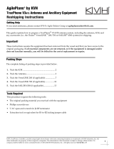
2.1.2 SAILOR 4338A Below Deck Unit (BDU)
The BDU is the central unit in the system. It contains all user interfaces and handles all
communication between the ADU and the local communication units (phones, computers
etc.). The BDU has Built-In Test Equipment (BITE) for Power On Self-Test (POST) and
Continuous Monitoring (CM). It comes in two versions, one designed for wall or desktop
installation, and one designed for installation in a 19” rack. The BDU supplies 42VDC to the
antenna through a single coaxial cable. The DC input for the BDU is designed for both
12VDC/24VDC power supply.
Figure 2-1: SAILOR 4300 L-Band System

General description
2-2 Chapter 2: Introduction 98-158670-D
2.1.3 SAILOR 4352 Above Deck Unit (ADU)
The ADU consists of an antenna with an RF-unit, unit for antenna control and GPS antenna.
The ADU is dedicated to the Iridium system. All communication between the ADU and BDU
passes through a single coaxial cable. The ADU is protected by a thermoplastic radome.
2.1.4 Data sessions and voice calls
The SAILOR 4300 L-Band System provides data connection and up to three simultaneous
IP voice calls. Both data and voice services is accessed through the service and the three
user LAN ports depending on configuration.
Data services are available on any of the LAN ports. The Certus data service define multiple
data flows as shown in the table below:
Figure 2-2: Data sessions with the SAILOR 4300 L-Band System
Name Services
Post-paid Data, voice and DHCP server
Secondary 1 Data
Table 2-1: Data services
Power
Terminal
Antenna
Power
I/O
LAN
Service
Reset
Antenna
DC-Input 12-24 VDC; 14-5.5 A
SIM-Card
12-24 VDC
Below Deck Unit
Above Deck Unit
TT-4338A
TT-4352A
cable
- Installation on bigger vessels: RG214/U up to 100 m length
Connector type: TNC
- Installation in a mechanically protected environment and
Cable requirements:
*
WLAN
Wireless SIP Phones
Wired IP Handset
Notebook
Power
PoE adapter
SIP Phone
Recommended
*
shorter distances: RG223/U up to 25 m length

Part numbers
98-158670-D Chapter 2: Introduction 2-3
2222
Introduction
All user ports are default attached to Post-paid data flow. A user port can be attached to
any other flow depending on configuration.
All flows are available through the Service port via VLANs. Each flow’s VLAN ID is shown in
table Table 4-10 on page 4-21.
Each flow has three modes: off, manual (default) and automatic. If a flow is in manual
mode, the data session is stopped on terminal startup and can easily be started and stopped
from the Service or Mobile web interface. If a flow is in automatic mode, the data session
will automatically start when traffic is detected. Automatic mode is persistent across
reboots.
The BDU communicates directly with SIP phones on any of the LAN ports. The terminal SIP
server is available on the Post-paid data flow only. Be aware that if connected to the service
port the SIP phone has to setup VLAN tagging.
For configuration and setup of voice and data services see Configuration on page 4-1.
2.1.5 IMEI and IMSI number
The terminal has an IMEI number which is stored by Iridium. The IMEI is printed on the
ADU type label and on the dashboard page.
The IMSI number is printed on the SIM card which you have received from your airtime
provider.
2.1.6 Emergency calls
Iridium Certus Terminals support several emergency services internationally.
Ship personnel should in general use GMDSS equipment in the event of an emergency.
2.2 Part numbers
This installation manual is for the SAILOR 4300 L-Band System and is applicable to the
following part numbers:
Secondary 2 Data
Secondary 3 Data
Secondary 4 Data
Name Services
Table 2-1: Data services (Continued)
Part number Description
404338A-00500 SAILOR 4338A Below Deck Unit (Bulk)
404338A-00510 SAILOR 4338A Below Deck Unit (19” rack)
404352A-00500 SAILOR 4352A Above Deck Unit
Table 2-2: Part numbers for the SAILOR 4300 L-Band System

Part numbers
2-4 Chapter 2: Introduction 98-158670-D

98-158670-D 3-1
Chapter 3
3333
Installation
Installation 3
This chapter has the following sections:
•What’s in the box
•Site preparation
•Installation of the ADU
•Installation of the BDU
•Interfaces of the BDU
•Commissioning (Iridium Service Provider)
3.1 What’s in the box
3.1.1 To unpack
Unpack the ADU and the BDU. Check that the following items are present:
• SAILOR 4338A Below Deck Unit (bulk or 19" rack variant)
• SAILOR 4352A Above Deck Unit
• Accessory kit for SAILOR 4352A Above Deck Unit
•Power cable
• Antenna cable
•Ethernet cable
•User manual
• Installation guide
3.1.2 Initial inspection
Inspect the shipping carton immediately upon receipt for evidence of damage during
transport. If the shipping carton is severely damaged or water stained, request that the
carrier's agent be present when opening the carton. Save the carton packing material for
future use.
After unpacking the system, inspect it thoroughly for hidden damage and loose
components or fittings. If the contents are incomplete, if there is mechanical damage or
defect, or if the system does not work properly, notify your dealer.
3.1.3 Tools needed
No special tools are needed.
WARNING! To avoid electric shock, do not apply
power to the system if there is any sign of shipping
damage to any part of the front or rear panel or the
outer cover. Read the safety summary at the front of this
manual before installing or operating the system.

Site preparation
3-2 Chapter 3: Installation 98-158670-D
3.2 Site preparation
3.2.1 General site considerations
For optimum system performance, some guidelines on where to install the components of
the SAILOR 4300 L-Band System must be followed. It is recommended to mount the ADU
in a location with as much 360° free line of sight to the satellites as possible. The ADU must
be mounted on stiffened structures with a minimum of exposure to vibrations. A small
platform or short mast must provide rigid support for the antenna fastening bolts and a
rigid interface to the ship.
The antenna is designed for harsh environmental conditions at sea, both in regard to
vibration amplitude and speed. The antenna system performs optimally when mounted on
a properly designed foundation. When mounting the antenna the overall goal is to establish
a foundation which is as rigid as possible.
Painting the radome
Customers may wish to paint the radome in order to match the vessel’s colour. Any paint
used must be non-metallic based. Painting the radome may impact RF performance and
may lead to over-heating, causing the antenna to go in safe mode (switch off).
Cobham SATCOM recommends that the radome should NOT be painted, Painting the
radome may void the general warranty regarding material and workmanship etc. It is only
the performance that cannot be guaranteed.
Modifying the radome or using another radome
The SAILOR 4300 L-Band System comes with a type-approved radome fitted from the
factory. This radome is specifically designed for a minimal loss of RF performance for this
specific antenna. Insertion loss reduces the available signal and decreases the effective
radiated power and G/T (the ability to receive a weak signal). Modifying the radome or using
another radome may increase the antenna side lobes, resulting in interference with other
communication systems and thereby void satellite operator approvals. Other electrical
effects on antenna performance of another radome, or of modifying the radome, include a
change in the antenna beam width and shifting of the antenna bore sight.
Cobham SATCOM recommends that the radome should NOT be modified or changed to
another type. Exchanging or modifying the radome will always void the general warranty.

Site preparation
98-158670-D Chapter 3: Installation 3-3
3333
Installation
3.2.2 Safe access to the ADU: Radiation hazard
The SAILOR 4300 L-Band System ADU has a minimum safety distance of 0.7 m from the
ADU while it is transmitting.
3.2.3 Mounting considerations
For optimum system performance, some guidelines on where to install or mount the
SAILOR 4300 L-Band System must be followed. Mounting and placement details are
included in this section.
1. Make sure there is clearance to potentially blocking objects.
2. Place the antenna preferably on a mast with a free and unobstructed view extending
from (at least) -30° below horizontal throughout the entire hemisphere and in all
azimuth directions. If you place the antenna directly atop the ship superstructure, or on
the ship bridge roof, this will compromise the roll-performance of the system due to the
blockage caused by the ship structure.
3. Place the antenna on a rigid structural connection to the hull or structure of the ship.
Parts of the ship with heavy resonant vibrations are not suitable places for the antenna.
3.2.4 Interference from radar, GNSS, L-band and other transmitters
The ADU must be mounted as far away as possible from the ship’s radar and high power
radio transmitters, because they may compromise the ADU performance. RF emission from
radars might actually damage the ADU. The SAILOR 4300 L-Band System ADU itself may
also interfere with other radio systems.
Figure 3-1: Radiation hazard, safety distance
0.7 m
0.7 m
0.7 m
25°
Note
Do not place the ADU close to interfering signal sources or receivers. For allowed
distances to other transmitters see Figure 3-5: Recommended distance to
transmitters (m) for frequencies below 1000 MHz on page 3-7. We recommend
testing the total system by operating all equipment simultaneously and verifying
that there is no interference.

Site preparation
3-4 Chapter 3: Installation 98-158670-D
Radar
Since a radar radiates a fan beam with a horizontal beam width of a few degrees and a
vertical beam width of up to +/- 15°, the worst interference can be avoided by mounting the
ADU at a different level – meaning that the ADU is installed minimum 15° above or below
the radar antenna. Due to near field effects the benefit of this vertical separation could be
reduced at short distances between radar antenna and the SAILOR 4300 L-Band System
ADU. Therefore it is recommended to ensure as much vertical separation as possible when
the SAILOR 4300 L-Band System ADU has to be placed close to a radar antenna.
Radar distance
The minimum acceptable distance (d min.) between a radar and the ADU is determined by
the radar wavelength/frequency and the power emitted by the radar. The tables below
show some “rule of thumb” minimum separation distances as a function of radar power at X
and S band. If the d min. separation listed below is applied, antenna damage is normally
avoided. “d min.” is defined as the shortest distance between the radar antenna (in any
position) and the surface of the SAILOR 4300 L-Band System ADU. d min indicates safe
separation distance. Larger separation is recommended for operational performance.
Figure 3-2: Interference with the vessel’s radar
Min. 15°
d min. 5 m
Min. 15°
X-band (~ 3 cm / 10 GHz) damage distance
Radar power SAILOR 4352A ADU
d min. at 15° vertical separation d min. at 60° vertical separation
0 – 10 kW 1.0 m 1.0 m
30 kW 2.0 m 1.0 m
50 kW 3.3 m 1.7 m
Table 3-1: Minimum radar separation, X-band
/