Page is loading ...

TracPhone®LTE-1 Global
Installation Guide

TracPhone LTE-1 Global
Installation Guide
1
KVH, TracPhone, and the unique light-colored dome with dark contrasting baseplate (Reg. No. 2,864,752) are registered
trademarks of KVH Industries, Inc. All other trademarks are property of their respective companies. The information in this
document is subject to change without notice. No company shall be liable for errors contained herein.
© 2021 KVH Industries, Inc., All rights reserved. 54-1276-01 Rev. B
This guide explains how to install the TracPhone LTE-1 Global antenna system on a vessel.
Operation instructions are provided in the Quick Start Guide.
Installation Steps
Appendices
Who Should Install the System?
To ensure a safe and effective installation, KVH recommends that a KVH-authorized marine
technician install the TracPhone antenna. KVH-authorized technicians have the tools and
electronics expertise necessary to install the system. To find a technician near you, visit
www.kvh.com/wheretogetservice.
Activating the System
For your convenience, the system can be activated remotely in advance using the information on
the QR code label located on the Quick Start Guide. By using the QR code, the antenna serial
number will automatically be populated in the online activation form. Alternatively, you can go to
www.kvh.com/lteglobalactivate and enter the serial number printed on the label.
Technical Support
Phone: +1 401.847.3327
Email: [email protected]
Hours: 24/7/365
1. Inspect Parts and Get Tools ..................3
2. Plan the Antenna Installation...............4
3. Prepare the Antenna Site ......................5
4. Prepare the Antenna..............................6
5. Mount the Antenna................................8
6. Mount the PoE Injector..........................9
7. Wire the PoE Injector...........................10
8. Test and Activate the System .............12
9. Connect to the Built-In Network .......13
10. Configure the Built-In Wi-Fi...............14
11. Connect to an Existing Network........16
12. Set Up Wi-Fi Calling............................17
13. Educate the Customer .........................18
A. Advanced Network Settings ..............19 B. Wiring Diagram....................................21

2
This icon indicates a danger, warning, or caution notice. Be sure to read these carefully to avoid
injury.
WARNING
Risk of Electric Shock
To avoid electric shock, do not open the Power-over-Ethernet (PoE) injector enclosure or any
component inside the antenna dome. There are no user-serviceable parts inside.
WARNING
Risk of Electric Shock
If any component of the TracPhone LTE-1 system becomes damaged and/or no longer functions
normally, disconnect it from vessel power, secure it from unintended operation, and contact KVH
Technical Support (see “Technical Support” on page 1). All repairs or modifications must be performed
by a trained, KVH-certified technician. If you are a KVH-certified technician, you still must contact
KVH Technical Support prior to conducting any repairs or modifications to the equipment.
WARNING
Risk of Explosion
Do not operate the PoE injector (or any other electrical device) in an environment where flammable
gases, vapors, or dusts are present. In addition, do not operate the PoE injector in an environment with
a temperature outside its 5º F to 131º F (-15º C to 55º C) temperature range.
WARNING
Risk of Electric Shock
Failure to ground the TracPhone LTE-1 system properly to ship’s ground will cause an unsafe floating
ground condition, risking potentially lethal electric shock. See “Wire the PoE Injector” on page 10 for
details on the proper grounding of the equipment.
CAUTION
RF Radiation Hazard
The antenna transmits up to 0.5 watts of radio frequency (RF) energy that is potentially harmful.
Whenever the system is powered on, make sure everyone stays more than 10 inches (25 cm) away from
the antenna. Additionally, the antenna must not be co-located or operate in conjunction with any other
antennas or transmitters except in accordance with FCC multi-transmitter procedures.
Important Safety Information

3
Before you begin, follow these steps to ensure
you have everything needed to complete the
installation.
a. Unpack the box and ensure it contains
everything shown on the Kitpack Contents
List. Save the packaging for future use.
b. Carefully examine all of the supplied parts to
ensure nothing was damaged in shipment.
c. Gather the tools and materials listed below.
You will need these items to complete the
installation.
• Flat-head and Phillips screwdrivers
• Electric drill with 1/8" (3 mm) and
1/4" (6 mm) bits
• Hole saw of desired diameter (for cable
access hole, see Figure 5 on page 5)
• Socket wrenches
• Light hammer and center punch
• Adhesive tape, and scriber or pencil
• Silicone sealant or equivalent
•Multimeter
• Wi-Fi-enabled mobile device, such as
a laptop PC, or Apple® iOS or
Android™ smartphone/tablet
Always lift the antenna by the baseplate and
never by the radome or any portion of the
internal antenna assembly (see Figure 1).
IMPORTANT!
Antenna
Power-over-Ethernet (POE) Injector
Radome
Baseplate
Figure 1: TracPhone LTE-1 System Components
Inspect Parts and Get Tools
1

4
Before you begin, consider the following antenna
installation guidelines.
• Minimize blockage. Optimal performance
requires a 360º clear view of the horizon at
the highest possible vantage point to receive
cellular signals. The fewer obstructions, the
better the system will perform (see Figure 2).
• Consider the distance between your antenna
and any radar. Most radar transmitters emit
RF energy within an elevation range of -15º to
+15º (see Figure 3). Therefore, mount the
antenna outside of this elevation range and at
least 3 ft (1 m) away from the radar.
• Make sure the mounting surface is wide
enough to accommodate the antenna’s base
(see Figure 4). Also make sure it is flat, level,
strong enough to support the antenna’s
weight, and rigid enough to prevent antenna
vibration.
• Be sure to mount the antenna near enough to
the PoE injector belowdecks to allow you to
connect the KVH-supplied 50 ft. (15 m)
CAT-6 Ethernet cable between them, while
still maintaining slack in the cable for a
sufficient service loop (see page 7).
NOTE: If you need to use a longer cable, optional
75 ft (22 m) (part no. 32-1332-0075) and 100 ft
(30 m) (part no. 32-1332-0100) Ethernet cables are
available from KVH.
Figure 2: Blockage from Obstruction
Blocked!
TracPhone Antenna
Mast
Look Angle
Vessel
Platform
-30° to 30°
Be sure to follow the guidelines below.
Damage caused by an improper installation is
not covered under KVH warranty.
IMPORTANT!
Figure 3: Distance from Radar
+15°
-15°
3 ft (1 m)
Minimum
Potential RF
Interference
Radar
Never place the antenna in the beam path of
the radar, regardless of distance. The radar’s
energy may damage the antenna or impair its
performance.
IMPORTANT!
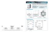
4 x Ø0.28"
(Ø0.7 cm)
Ø13.5"
(Ø34.3 cm)
6.4"
(16.3 cm)
3.2"
(8.1 cm) 6.4"
(16.3 cm)
Cable Entry
13.3"
(33.8 cm)
Side View
Bottom View
Figure 4: Antenna Dimensions
Plan the Antenna Installation
2

5
Once you have identified a suitable antenna
mounting site, according to the guidelines
provided on page 4, follow these steps to prepare
the mounting site for installation.
a. Unfold the antenna mounting template
(supplied in the subscriber Welcome Kit) and
place it onto the mounting surface. Make sure
the “FWD” (forward) arrow points toward
the bow and is parallel to the vessel’s
centerline (see Figure 5). Tape in place.
b. Using a light hammer and center punch,
mark the locations for the four mounting
holes and cable access hole on the mounting
surface in the locations indicated on the
template.
c. Drill a 1/4" (6 mm) hole at the four mounting
hole locations you marked in Step b. Later,
you will insert four #10-32 screws through
these holes to secure the antenna to the
mounting surface.
d. Using a hole saw, drill the cable access hole in
the location you marked in Step b. Be sure to
size the hole appropriately to maintain a
cable bend radius of at least 2.6" (6.6 cm). If
the hole location is in the center of the
antenna mounting hole pattern, the diameter
of the cable access hole must not exceed
3.5" (89 mm).
e. Smooth the edges of the cable access hole to
protect the cable. Later, you will route the
antenna’s Ethernet cable through this hole
and into the vessel.
f. Clean and dry the antenna mounting surface.
g. Peel off the paper backing from the supplied
foam seal to expose the adhesive. Then press
the foam seal down firmly onto the mounting
surface, ensuring the hole in the foam seal
aligns with the cable access hole in the
mounting surface (see Figure 6).
13.5"
(34.3 cm)
3.2" (8.1 cm)
6.4"
(16.3 cm)
3.2" (8.1 cm)
6.4"
(16.3 cm)
4 x Ø0.25"
(Ø0.6 cm)
Mounting Holes
Antenna Base
1.75" (4.4 cm)
1.25" (3.2 cm)
Maximum
Cable Access Hole
Ø3.5" (Ø8.9 cm)
Recommended
Cable Access Hole
Ø1.0" (Ø2.5 cm)
4 x Seal
Guides
Figure 5: Antenna Mounting Holes Layout
Align With
Cable Access
Hole
Figure 6: Foam Seal
Prepare the Antenna Site
3

6
Follow these steps to prepare the TracPhone
LTE-1 antenna for installation.
a. Attach the four rubber mounting feet
(supplied in kit) to the bottom of the antenna at
the locations shown in Figure 7.
NOTE: If the optional mounting bracket was
purchased with the system (KVH part no. 72-0409),
install it first according to its installation
instructions.
b. Remove the four #8-32 screws securing the
radome to the antenna (see Figure 8).
c. Carefully lift the radome straight up until
clear of the antenna assembly and set it aside
in a safe place.
d. Note the antenna serial number, factory
default SSID and password for the built-in
Wi-Fi provided on the label inside the
antenna dome (see Figure 9).
Figure 7: Attaching the Rubber Feet
Be sure to install the rubber feet. They are
required to isolate the antenna from vibration.
IMPORTANT!
Figure 8: Removing the Radome
#8-32 Screw (x4)
If you keep the radome topside, secure it with
a lanyard to prevent it from falling overboard.
Also, do not place the radome on a hot steel
deck – the heat may warp the radome.
IMPORTANT!
The QR code on the label is provided as a
backup to the label located on the Quick Start
Guide and is intended for subscriber use only
for activation.
IMPORTANT!
Figure 9: Location of the Serial Number and QR Code
Can’t scan? Go to:
www.kvh.com/LTEactivate
Serial No. 123456789
WiFi Name (SSID):
TracPhone LTE1-F429
Wi-Fi Password:
12345678
Can’t scan? Go to:
www.kvh.com/LTEGlobalActivate
Serial No. 123456789
WiFi Name (SSID):
TracPhone LTE1-F429
Wi-Fi Password:
12345678
Prepare the Antenna
4

7
e. Remove but do not discard the push-in
grommet from the cable entry hole in the
baseplate.
f. Feed the CAT-6 Ethernet cable (supplied in kit)
through the cable entry hole. Then, leaving
1.5 ft (46 cm) of cable for an adequate service
loop, and maintaining at least a 2.6" (6.6 cm)
bend radius, route the cable as shown in
Figure 10.
g. Slide the Ethernet cable through the split in
the snap-in grommet inside the baseplate (see
Figure 11). Then secure the cable by rotating
the grommet until the split is facing down.
h. Connect the Ethernet cable to the Wi-Fi
modem’s “LAN/WAN” port (see Figure 10).
i. Secure the service loop to the antenna
mounting plate with the preinstalled
#10-32 screw and P-clip (see Figure 11). Then
tighten the screw and P-clip to 31 in-lbs of
torque.
j. Attach the push-in grommet that you
removed in Step e to the cable near the cable
entry hole. Then reinstall the grommet in the
cable entry hole.
k. Route the other end of the cable along the
cable channel underneath the baseplate and
belowdecks through the cable access hole.
Always maintain at least a 2.6" (6.6 cm) bend
radius.
l. Weatherproof and seal the cable access hole
as required.
Figure 10: Connecting the Ethernet Cable
Status
Wi-Fi
Cellular
LAN/WAN
PoE IN
LAN/WAN
Cable Entry Hole
Figure 11: Securing the Ethernet Cable
Snap-in
Grommet
Push-in Grommet
in Cable Entry Hole
P-clip and
#10-32 Screw
Continued Prepare the Antenna
4

8
Follow these steps to mount the antenna to the
mounting surface.
a. Place the antenna baseplate over the holes
drilled in the mounting surface. Ensure the
“Forward” arrow inside the baseplate points
toward the bow and is parallel to the vessel’s
centerline (see Figure 12).
b. Apply a thin layer of the supplied anti-seize
lubricant to the threads of the four
#10-32 Phillips screws.
c. At each of the four baseplate mounting holes,
place a 7/16"-diameter flat washer on a
#10-32 Phillips screw and insert the screw
into the hole from above (see Figure 13).
d. Secure each mounting bolt to the mounting
surface using a 3/4 "-diameter flat washer
and a #10 lock nut from below. Using hand
tools, tighten all four screws until the four
rubber feet on the baseplate are bottomed
against the mounting surface and the foam
seal is fully compressed.
e. Reinstall the radome onto the antenna. The
radome’s “LTE-1 TracPhone” labels should
face fore and aft. Secure in place with the four
#8-32 screws you removed earlier. Hide and
protect the screws with the plastic screw caps
(supplied in kit).
CAUTION
Be sure to observe the safe handling
instructions in the Material Safety Data Sheet
(MSDS) provided with the anti-seize
lubricant.
Figure 12: Forward Arrow (Example)
Be sure to insert the mounting bolts from
above and use the supplied hardware for a
secure installation.
IMPORTANT!
Use only manual hand tools to tighten the
mounting screws. The torque from a power
tool might distort the antenna baseplate.
IMPORTANT!
#10-32 x 3" Screw
#10 Flat Washer
Antenna Base
Foam Seal
Mounting Surface
#10 Flat Wide Washer
Rubber Foot
(7/16" diameter)
(3/4" diameter)
#10 Lock Nut
IMPORTANT:
Apply anti-seize
to threads
Figure 13: Mounting Hardware
Mount the Antenna
5

9
Follow these steps to mount the PoE injector in a
suitable location.
Select a Location
Consider these installation guidelines.
• Select a cool, dry, well-ventilated area
belowdecks away from any heat sources or
salt spray.
•Be sure the PoE injector’s power LED light
will be visible to the user.
• Select a location that will provide adequate
clearance for the PoE injector dimensions (see
Figure 14) and leave plenty of room to
accommodate adequate service loops and
strain-relief.
Mount the PoE Injector
Follow these steps to install the PoE injector.
a. Using the PoE injector itself as a guide, mark
the locations of each of the four mounting
holes (see Figure 14).
b. Drill a 1/8" (0.3 cm) hole at the four mounting
hole locations you marked in Step a.
c. Secure the PoE injector using fasteners that
are appropriate for the mounting surface’s
construction.
Top View
3.1"
(7.9 cm)
3.8"
(9.7 cm)
Mounting Hole
4 x Ø 0.13"
(Ø 0.3 cm)
1.4"
(3.6 cm)
2.2"
(5.7 cm)
Side View
LED Light
Figure 14: PoE Injector Dimensions
Mount the PoE Injector
6

10
Follow the steps below and on page 11 to wire
the PoE injector to the antenna and connect
power to the system.
Connect the PoE Injector to the Antenna
Connect the Ethernet cable from the antenna to
the “To KVH Antenna” Ethernet port on the PoE
injector (see Figure 15).
Connect Power to the PoE Injector
NOTE: An optional 24 VDC AC-DC power supply
(5 A, 120 W) is available from KVH (part no.
72-0857).
a. Before you begin, disconnect vessel power.
b. Connect the PoE injector’s power cable wires
to the supplied 4-position terminal strip
connector as shown in Figure 16 and
described below:
• Connect the green “Ground” wire to
ship’s ground.
• Connect the black “VIN-” wire to DC
Return.
NOTE: The third terminal is unused.
• Connect the red “VIN+” wire to the
vessel’s 12-24 VDC power source.
Figure 15: PoE Injector Antenna Connection
Deck
To KVH
Antenna
WARNING
Connect to
PoE Device only
Do not connect anything other than the
antenna’s Ethernet cable to the PoE injector’s
“To KVH Antenna” Ethernet port. The PoE
injector supplies voltage that will damage
other devices, such as laptop computers.
IMPORTANT!
Figure 16: System Power Connection
Red
BlackGreen
Fuses
(4A 32V SFE)
DC Power
(12-24 VDC)
DC Return
Ground VIN- VIN+n/c
Not
Used
Ground
Input
Terminal Strip
A 5A circuit breaker should be installed
between the PoE injector and vessel power to
turn the TracPhone LTE-1 system on and off.
IMPORTANT!
Wire the PoE Injector
7

11
Check For Proper Grounding
a. Check for proper grounding by using a
multimeter to measure the AC and DC
voltages at the ground and DC return
terminal pins (see Figure 16 on page 10). The
measured voltage should be less than 2 VAC
and 2 VDC. A higher voltage indicates a
dangerous floating ground condition.
b. Reconnect vessel power and turn on the
circuit breaker to apply power to the antenna
system. Within seconds, the Power light on
the PoE injector should illuminate green (see
Figure 17).
c. Repeat Step a with the circuit breaker turned
on, looking for the same measured result.
WARNING
If you measure 2 volts or greater at the power/
ground cable’s terminal connector, notify the
ship’s electrician or authorized vessel
representative immediately. This is a
dangerous condition. Do not touch the PoE
injector or connect anything to it until the
problem is fixed.
Power Light
Figure 17: PoE Injector Power Light Location
Continued Wire the PoE Injector
7

12
Test the System
Before continuing, test the system for proper
operation. The TracPhone LTE-1 system’s factory
default SSID should be visible on your mobile
device.
a. Ensure that you are within range of the
antenna’s built-in Wi-Fi router (30 ft (9 m),
depending on the layout and structure of the
vessel).
b. Find the LTE system’s SSID on your mobile
device under Wi-Fi settings (see Figure 18).
Activate the System
The subscriber needs to activate the system for
LTE service. To begin activation, instruct the
subscriber to scan the QR code located on the
Quick Start Guide. They can also visit
www.kvh.com/lteglobalactivate to begin the
activation process.
Figure 18: LTE System SSID on Android Phone (Example)
Test and Activate the System
8

13
Follow the steps below to connect to the built-in
network. To use an existing local area network
(LAN), refer to “Connect to an Existing Network”
on page 16.
Connecting Using the Built-In Wi-Fi
NOTE: The LTE system’s built-in Wi-Fi range is
nominally within 30 ft (9 m) of the antenna. To extend
that range, connect a wireless access point (WAP) to the
network. In all cases, an Ethernet connection will
provide the fastest possible speeds.
a. Select the LTE system’s factory default SSID on
your mobile device.
b. Enter the factory default Wi-Fi password to
access the network.
c. If the customer wants to use a different SSID
(network name) and/or password, follow the
steps in “Configure the Built-In Wi-Fi” on
page 14.
Connecting Directly through the LAN Port
Connect a standard Ethernet cable from the
Ethernet port on your computer to the ”LAN” port
on the PoE injector (see Figure 19).
To connect multiple computers, use a simple
switch (see Figure 19).
By default, the TracPhone LTE-1 system’s
built-in Wi-Fi router has an IP address of
192.168.55.1 and assigns IP addresses to
connected devices automatically. If this
configuration conflicts with an existing
onboard network or you would prefer to
manually assign static IP addresses to
connected devices, refer to “Advanced
Network Settings” on page 19 for instructions.
IMPORTANT!
Figure 19: Connect Using the Built-In Wi-Fi and LAN Port
PoE
Antenna
LAN
4 3 2 18 7 6 5
POE 48V
+
Wi-Fi
Ethernet
Switch
OR
(not supplied)
Connect to the Built-In Network
9
Network Option 1

14
The TracPhone LTE-1 system contains a built-in
Wi-Fi router that can be configured in a variety of
ways to meet the subscriber’s needs. If you need to
rename the SSID, change the Wi-Fi password, or
disable the built-in Wi-Fi, follow these steps.
a. Connect a standard Ethernet cable from the
Ethernet port on your computer to the ”LAN”
port on the PoE injector.
NOTE: As an alternative, you could access the router’s
web interface via the built-in Wi-Fi. But you would
immediately lose your connection upon modifying the
Wi-Fi settings.
b. Start your web browser and enter
https://192.168.55.1 to access the web interface.
c. Log in using the following credentials:
Username: admin
Password: TracPhoneLTE1
d. At the Dashboard, if you want to turn off the
built-in Wi-Fi, you can use the drop-down
menu under “Wi-Fi AP” (see Figure 20). This
change takes effect immediately.
e. If you want to change the SSID (network
name) or password, select the AP tab or select
Details under “Wi-Fi AP” (see Figure 20).
Then select Add (see Figure 21).
f. Make any changes to the settings requested by
the subscriber (see Figure 22):
• SSID: Assign a unique name provided by
the subscriber for the Wi-Fi network.
•Enable: Make sure it is checked to enable
this Wi-Fi connection.
•Security Policy: Select “WPA2-Personal”
to secure the Wi-Fi network.
•Shared Key: Enter a unique password
provided by the subscriber (must be 8-20
characters).
Figure 20: Built-in Router Dashboard
Figure 21: Adding a New SSID at AP Page
Failure to apply a security policy and unique
password will make the LTE system’s Wi-Fi
network vulnerable to outside intrusion.
IMPORTANT!
Figure 22: Built-In Wi-Fi Settings
Configure the Built-In Wi-Fi
10
Network Option 1

15
g. When you are finished, select Save. Then
select Apply Changes in the upper right-
hand corner (see Figure 23). The button
changes to “Confirm” on rollover.
h. At the AP page, select the X button next to the
factory default SSID to delete it (see
Figure 24). Be careful not to delete the new
SSID you just created.
i. In the rare event that you need to change the
Wi-Fi channel, go to AP > Settings. Choose
the desired channel and select Save (see
Figure 25). Then select Apply Changes.
Figure 23: Applying Changes
Figure 24: Deleting Factory Default SSID
Figure 25: Built-In Wi-Fi Channel Setting
Continued Configure the Built-In Wi-Fi
10
Network Option 1

16
If the subscriber already has an existing LAN on
the vessel, you can connect its router to the
TracPhone LTE-1 system. Then all devices on the
network will have access to the LTE service.
Follow the steps below to set up this
configuration.
a. Turn off the built-in Wi-Fi on the LTE system.
Refer to “Configure the Built-In Wi-Fi” on
page 14 for details.
b. Connect a standard Ethernet cable from the
“WAN” (Internet) port on the network router
to the ”LAN” port on the PoE injector (see
Figure 26).
NOTE: If the IP address of the existing router is
192.168.55.1, you will need to change the IP address
of either the router or the LTE system. Refer to
“Advanced Network Settings” on page 19 for details.
Figure 26: Connect Using an Existing Network
Onboard Network (LAN)
12VDC
POWER
ResetEthernet Internet4321
Wireless Router
Ethernet
Wi-Fi
PoE
LAN
(not supplied) WAN
Connect to an Existing Network
11
Network Option 2

17
To use the TracPhone LTE-1 system to make and
receive voice calls, you must either have a
smartphone that supports Wi-Fi calling or an
app, such as Skype™ or WhatsApp© Messenger
that approximates the feature. To enable the
Wi-Fi calling feature on your phone, follow the
basic steps below or refer to your device’s user
documentation.
Enabling Wi-Fi Calling on an iPhone
a. Navigate to Settings > Phone > Wi-Fi
Calling.
b. Using the slider, turn on “Wi-Fi Calling on
This iPhone” (see Figure 27).
Enabling Wi-Fi Calling on an Android Phone
(Android version 8.0.0 or later)
a. Tap the Phone app.
b. Navigate to Settings > Wi-Fi Calling.
c. Using the slider, enable Wi-Fi calling
(changes from “Disabled” to “Ready for
calls”) (see Figure 28).
(Android versions earlier than 8.0.0)
a. Navigate to Settings > Wireless & Networks
> More... > Wi-Fi Calling > Wi-Fi Calling.
b. Using the slider, enable Wi-Fi calling
(changes from “Disabled” to “Ready for
calls”) (see Figure 28).
Figure 27: Wi-Fi Calling Enabled on an IPhone
Figure 28: Wi-Fi Calling Enabled on an Android Phone
Set Up Wi-Fi Calling
12
Optional

18
Deliver the Welcome Kit to the subscriber and
explain how to use the system. Ensure the
subscriber understands the following.
•How to:
• Apply power to the system
• Access the Internet
• Access the router’s web interface and
customize the built-in Wi-Fi settings
• Perform general troubleshooting
• The radome must remain installed on the
antenna at all times, as it protects the antenna
from wind, rain, and debris.
For More Information
Refer to the Quick Start Guide or the Help
provided at kvh.com/lteglobalhelp.
Figure 29: Welcome Kit
Educate the Customer
13

19
In addition to built-in Wi-Fi settings, you can
change other network settings at the router’s web
interface:
•Changing the Built-In Router’s IP Address:
By default, the system’s built-in router has an
IP address of 192.168.55.1. If this
configuration conflicts with an existing
onboard network (e.g., another router on the
vessel is using the same address), you can
change the built-in router’s IP address.
•Disabling DHCP to Manually Set IPs:
By default, the system’s built-in router
assigns IP addresses to connected devices
automatically. If you prefer to manually
assign static IP addresses to your devices,
you can turn off the router's DHCP server.
Follow these steps to make either change.
1. Connect your laptop or mobile device to the
LTE system via either its built-in Wi-Fi or the
“LAN” port on the PoE injector.
2. Start your web browser and enter
https://192.168.55.1 to access the web
interface.
3. Log in using the following credentials:
Username: admin
Password: TracPhoneLTE1
4. At the router’s web interface, go to the
Network page.
5. Under LAN, select the Untagged LAN (see
Figure 30).
6. If you want to change the IP address, enter it
in the IP Address text box under “IP Settings”
(see Figure 31).
7. If you want to disable DHCP, clear (uncheck)
the DHCP Server: Enable check box under
“DHCP Server.”
The default network settings work well for
most installations. Do not change them unless
absolutely necessary.
IMPORTANT!
Figure 30: Untagged LAN on Router’s Network Page
Figure 31: LAN Network Settings
Advanced Network Settings
A
Appendix
/