Page is loading ...

EDUCATOR
2
Installation &
Configuration Manual
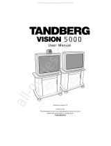
TANDBERG
TANDBERG
Software Version B4
Control Software V4.1
D50103-06
This document is not to be reproduced in whole
or in part without the permission in writing from:

TANDBERG Educator
2
2 Installation and Configuration Manual - D50103-06
Trademarks and copyright
COPYRIGHT © 2000, TANDBERG
1860 Michael Faraday Drive, Suite 250
Reston, Virginia 20190
Tel: 703-709-4281, Fax: 703-709-4231
All rights reserved. This document contains information that is proprietary to TANDBERG. No part of this publication
may be reproduced, stored in a retrieval system, or transmitted, in any form, or by any means, electronic, mechanical,
photocopying, or otherwise, without the prior written permission of TANDBERG.
Nationally and internationally recognized trademarks and trade names are property of their respective holders and are
hereby acknowledged.
Disclaimer
The information in this document is furnished for informational purposes only, is subject to change without prior notice,
and should not be construed as a commitment by TANDBERG.
The information in this document is believed to be accurate and reliable, however TANDBERG assumes no
responsibility or liability for any errors or inaccuracies that may appear in this document, nor for any infringements of
patents or other rights of third parties resulting from its use. No license is granted under any patents or patent rights of
TANDBERG.
The Applications Development Department of TANDBERG, wrote this document. We are committed to maintaining a
high level of quality in all our documentation. Towards this effort, we welcome your comments and suggestions
regarding the content and structure of this document. Please fax or mail your comments and suggestions to the
attention of:
Applications Development Department
1860 Michael Faraday Drive, Suite 250
Reston, Virginia 20190
Tel: 703-709-4281, Fax: 703-709-4231
Technical Support
For technical support, contact one of the following service centers:
USA Canada Europe & Asia Pacific
TANDBERG TANDBERG TANDBERG
1860 Michael Faraday Drive 6505 Trans-Canada Hwy. Philip Pedersens vei 22
Suite 250 Suite 610 1366 Lysaker, Norway
Reston, Virginia 20190 Montreal, Quebec Tel: +47 67 125 125
Tel: 703 709 4281 H4T 1S3 Fax: +47 67 125 234
Toll free: 800 889 7440 Tel: 514 748 5224 Video: +47 67 117 777
Fax: 703 709 4231 Toll free: 800 729 6990
Video: 703 437 6991 Fax: 514 748 5760 Mailing Address:
Email: helpdesk@tandbergusa.com Video: 514 744 5514 TANDBERG ASA
P.O. Box 92
1325 Lysaker, Norway

TANDBERG Educator
2
Installation and Configuration Manual - D50103-06 3
Table of Contents
Trademarks and copyright .............................................................................................................. 2
Disclaimer ....................................................................................................................................... 2
Technical Support ........................................................................................................................... 2
1 Introduction ............................................................................................................... 7
Manual Content .............................................................................................................................. 7
Conventions .................................................................................................................................... 7
System Description ...................................................................................................... 8
Control ........................................................................................................................................... 8
Touch Panel Control ....................................................................................................................... 8
Audio ............................................................................................................................................. 8
Audio Controls .................................................................................................................................8
Loudspeakers ................................................................................................................................. 8
Audio/Video Sources.................................................................................................................... 8
Instructor, Student, and Document Cameras .................................................................................. 8
Auxiliary Sources .............................................................................................................................8
VCR/DVD Player .............................................................................................................................8
PC Presenter .................................................................................................................................. 9
Student Monitors..............................................................................................................................9
Instructor Monitor(s)........................................................................................................................ 9
Touch Panel Video Window ............................................................................................................ 9
Power ............................................................................................................................................. 9
Optional Equipment.......................................................................................................................9
Document Camera...........................................................................................................................9
VCR (Video Cassette Recorder) ..................................................................................................... 9
DVD (Digital Versatile Disc) Player ..................................................................................................9
Monitor Upgrades ........................................................................................................................... 9
Additional Microphone .................................................................................................................... 9
Director Microphone ..................................................................................................................... 10
Touch and Talk Microphones ........................................................................................................ 10
Telephone Add-on ......................................................................................................................... 10
Pressure Mats (automatic camera positioning) ............................................................................ 10
TANDBERG Trackers (automatic camera positioning) ................................................................. 10
Auxiliary 35 mm Slide to Video Converter .................................................................................... 10
Auxiliary Room Camera with Wide Angle Lens ............................................................................ 10
Auxiliary High Quality VGA/SVGA Scan Converter ...................................................................... 10
Network Terminating Units NT1 and NT384 ................................................................................. 10
Installation ................................................................................................................. 11
Precautions ..................................................................................................................................11
Unpacking .................................................................................................................................... 11

TANDBERG Educator
2
4 Installation and Configuration Manual - D50103-06
Room Configuration and Setup................................................................................................. 12
NAM and TAM Location ................................................................................................................ 13
NAM and TAM Module Installation................................................................................................ 14
Cabling.......................................................................................................................................... 15
Cabling Configurations ................................................................................................................. 16
Touch Panel .................................................................................................................................. 16
Instructor ....................................................................................................................................... 17
Student ......................................................................................................................................... 18
AudioScience Microphone ............................................................................................................ 19
Network......................................................................................................................................... 19
ISDN BRI ...................................................................................................................................... 19
ISDN E1/T1................................................................................................................................... 19
External Network .......................................................................................................................... 19
Ethernet ........................................................................................................................................ 19
Network Terminating Units NT1 and NT384 ................................................................................. 20
Installing Optional Equipment ....................................................................................................... 20
Document Camera........................................................................................................................ 21
VCR ........................................................................................................................................... 21
DVD Player ................................................................................................................................... 22
Scan Converter ............................................................................................................................. 23
35mm Slide to Video Converter .................................................................................................... 23
PC Presenter ............................................................................................................................... 23
VGA ........................................................................................................................................... 23
VNC ........................................................................................................................................... 23
Pressure Mats............................................................................................................................... 24
TANDBERG Trackers ................................................................................................................... 25
Room Camera .............................................................................................................................. 25
Telephone Add-on ......................................................................................................................... 25
Touch and Talk Microphones ........................................................................................................ 25
The Director Microphone .............................................................................................................. 25
System Configuration ............................................................................................... 26
Protected Setup Page................................................................................................................... 26
Time and Date .............................................................................................................................. 26
System Set Up Button .................................................................................................................. 27
Key Pad ........................................................................................................................................ 27
Terminal Setup Page .................................................................................................................... 28
ISDN-BRI Settings ........................................................................................................................ 29
Switch Type ............................................................................................................................. 29
ISDN-BRI Settings................................................................................................................... 29
Advanced Setup ...................................................................................................................... 30
Call Quality .............................................................................................................................. 30

TANDBERG Educator
2
Installation and Configuration Manual - D50103-06 5
ISDN-PRI Settings ........................................................................................................................ 31
Switch Type ............................................................................................................................. 31
ISDN-PRI Settings................................................................................................................... 31
Advanced Setup ...................................................................................................................... 32
Call Quality .............................................................................................................................. 32
External Network Settings ............................................................................................................ 33
Call Control.............................................................................................................................. 33
Network Clocking .................................................................................................................... 33
Leased E1/T1 Description ............................................................................................................ 34
Network Type .......................................................................................................................... 34
Leased E1/T1 Settings ............................................................................................................ 34
Call Quality .............................................................................................................................. 35
Ethernet H.323 & IP Setup ........................................................................................................... 36
DHCP ...................................................................................................................................... 36
Current Active IP Status .......................................................................................................... 36
NAT ......................................................................................................................................... 36
Gatekeeper & Routing Settings .................................................................................................... 37
Streaming ................................................................................................................................ 38
Restart ..................................................................................................................................... 38
Equipment Setup Page ................................................................................................................. 39
Student/Instructor Camera............................................................................................................ 40
Sony WAVE Camera Setup (Student, Instructor) ......................................................................... 41
Document Camera........................................................................................................................ 42
VCR or DVD Player ...................................................................................................................... 43
Auxiliary Device #1 ....................................................................................................................... 44
Room Camera Setup .................................................................................................................... 44
Auxiliary Device #2 ....................................................................................................................... 45
Pressure Mats Configuration ........................................................................................................ 45
Audio Setup Page ......................................................................................................................... 46
Telephone Add-on ......................................................................................................................... 46
Audio Input Settings...................................................................................................................... 46
Audio Output Settings ................................................................................................................... 47
Input/Output Controls.................................................................................................................... 47
Room Properties ........................................................................................................................... 48
Restore Audio Defaults ................................................................................................................. 48
System Setup Page ...................................................................................................................... 49
External Control ............................................................................................................................ 50
Data Port Setup Page ................................................................................................................... 51
Data Mode .................................................................................................................................... 51
T120 Mode.................................................................................................................................... 52
Codec Test Page .......................................................................................................................... 52

TANDBERG Educator
2
6 Installation and Configuration Manual - D50103-06
List of Figures
Figure 1 Educator
2
Panel .................................................................................................................. 7
Figure 2 Recommended Room Layout ........................................................................................... 12
Figure 3 TAM Located in Instructor Desk/Podium ........................................................................... 16
Figure 4 TAM Located in Student Cart ............................................................................................ 16
Figure 5 Touch Panel Opening Page .............................................................................................. 26
Figure 6 Terminal Setup Page (ISDN-BRI Settings) ....................................................................... 28
Figure 7 Set Up Call Control Options .............................................................................................. 28
Figure 8 Terminal Setup ISDN-BRI Settings Page .......................................................................... 29
Figure 9 Terminal Setup ISDN-PRI Settings Page .......................................................................... 31
Figure 10 External Setup Page ......................................................................................................... 33
Figure 11 Leased E1/T1 Page .......................................................................................................... 34
Figure 12 Call Quality Configuration Screen ..................................................................................... 35
Figure 13 Ethernet Diagnostic Setup Page ....................................................................................... 36
Figure 14 Equipment Setup Page ..................................................................................................... 39
Figure 15 Audio Setup Page (with Input selected) ............................................................................ 46
Figure 16 System Setup Page .......................................................................................................... 49
Figure 17 Data Port Setup Page ....................................................................................................... 51
Abbreviations ............................................................................................................ 53
Appendix 1: AudioScience Microphone.................................................................. 54
AudioScience Microphone Parts Listing ....................................................................................... 54
Tools Required for Assembly and Installation ............................................................................... 54
Installation Considerations............................................................................................................ 55
Selecting a Mounting Location...................................................................................................... 56
Assembly and Installation Instructions.......................................................................................... 57
Appendix 2: The Tracker .......................................................................................... 59
Appendix 3: Installation and Setup, Educator/Tutor Extended Height Cart
(EHC-03) and Monitor Interface Box (MIB).......................................................... 60
Introduction ................................................................................................................................... 60
Monitor and Cart Installation ......................................................................................................... 60
Optional Acrylic Shelf Installation.................................................................................................. 61
Monitor Interface Box (MIB) Installation........................................................................................ 61
TAM Installation ............................................................................................................................ 61
Power Bar Installation ................................................................................................................... 62
Connecting the MIB ...................................................................................................................... 62
SVGA Connections ....................................................................................................................... 63
Monitor Setup ............................................................................................................................... 64
Touch Panel Setup........................................................................................................................ 65

TANDBERG Educator
2
Installation and Configuration Manual - D50103-06 7
1 Introduction
Welcome to the TANDBERG Educator
2
.
Educator
2
is a fully featured distance learning system. The heart of this system is a color touch panel incorporating
single screen operation and a video window that displays current local and remote site transmission. Educator
2
allows
control of multiple devices, such as room cameras, VCR’s, DVD players, document cameras.
Manual Content
This manual is designed to assist you in the installation and configuration of the TANDBERG Educator
2
. It assumes
that users have a fundamental knowledge of the system.
This manual is arranged in the order in which an Educator
2
user will need the information.
Conventions
Push button controls are fitted into the cover plate surrounding the touch-sensitive area of the control screen (touch
panel). Push button controls are DEPICTED LIKE THIS.
Touch panel buttons are depicted like this.
Hardware outlets, ports and elements are DEPICTED LIKE THIS.
Note: Text in this format pertains to the topic being discussed in regular text and is set aside to emphasize a
particular point.
WARNING: Text found in this format is vitally important for the correct configuration of Educator
2
. Please pay special
attention to these.
Figure 1 Educator
2
Panel

TANDBERG Educator
2
8 Installation and Configuration Manual - D50103-06
System Description
Control
Touch Panel Control
A 10.4" color touch panel is used to control the entire TANDBERG Educator
2
system. The touch panel with optional
integrated instructor microphone is typically placed on a desk.
Audio
Audio Controls
You can change the loud speaker sound level with the touch panel audio controls. You can also mute the
microphones to have a private conversation during a distance education session. The built-in echo canceller
dynamically trains itself to compensate for the acoustics of the room.
Loudspeakers
The system features speakers integrated into the instructor and student monitor carts.
Audio/Video Sources
Instructor, Student, and Document Cameras
The touch panel is used to control the position and zoom of all the cameras.
Auxiliary Sources
Two additional audio/video sources can be connected. These sources can be configured for a specific device such as
a PC scan converter, DVD player, 35mm slide to video converter, and a room camera.
VCR/DVD Player*
For systems that have one VCR installed, you can either play a videocassette during a distance education session or
record the session. If you have the optional Panasonic AG5700/5710 or PV-S9670, or Sony SLV models of VCR, or
the Sony DVP-models DVD player you can use the touch panel to control of the VCR/DVD player operation.
For systems that have two VCRs installed, you can simultaneously play one VCR and record with the other.
* European model will differ.

TANDBERG Educator
2
Installation and Configuration Manual - D50103-06 9
PC Presenter
A computer VGA connection is available as an input to the Educator
2
. This allows VGA of a PC to connected to the
system without using an external scan conversion unit. This input is capable of accepting 640x480, 800x600 or
1024x768 resolution.
Student Monitors
The student monitors are typically located side by side at the front of the classroom. Looking at the front of the
monitors, the motion monitor is located on the left. It displays the video image received from the remote site. The local
display/graphics monitor is located on the right. It displays the current transmission, duo video or the still image.
Instructor Monitor(s)
The instructor monitor(s) is typically located at the back of the classroom so that the instructor can see the remote
rooms from the front of the classroom. The monitor(s) are set to display the same as the student monitors.
Touch Panel Video Window
The video window can display the, remote site, current transmission, or the last sent / received still image. By
pressing on this window, the instructor can view the image full screen.
Power*
The SYSTEM ON and SYSTEM OFF buttons control the switched AC outlet on the TAM and the power control units.
All peripherals that are connected using this power outlet or power control device will be switched on or off when
these buttons are pressed.
Optional Equipment
Document Camera
The standard document camera is the TANDBERG Documentor camera with full touch panel control. Other cameras
that can be used are the ELMO EVSeries with RS232 Control, Sony VID-PSeries withRS232 Control and the
Wolfvision VZ series. The customer can also supply his own camera as long as it provides a composite video output.
VCR (Video Cassette Recorder)
The standard VCR (North America) is the Sony consumer SLV models with full touch panel control, but other VCRs
can also be configured.
DVD (Digital Versatile Disc) Player*
The DVD player can be controlled from both the touch panel and its own infrared remote control device.
Monitor Upgrades
All monitors can be upgraded from the standard 27" to either 32" or 36" monitors.
Additional Microphone
An additional AudioScience microphone is available, with cable, to allow coverage of large rooms.
* North America only.

TANDBERG Educator
2
10 Installation and Configuration Manual - D50103-06
Director Microphone
The Director microphone is a directional version of the AudioScience microphone. This ceiling mounted microphone
replaces the one on the touch panel allowing the lecturer more freedom of movement around the teaching area while
retaining good audio pick up.
Touch and Talk Microphones*
Touch and talk microphones can be added to allow a student control of their local microphone activation and their
image transmission. To active the microphone the student must press and hold the talk button. A maximum of 40 TNT
microphones can be connected to the system via a master electronics module.
Telephone Add-on*
This allows a telephone caller to be brought into the conference call, and hear and be heard by all other parties.
Pressure Mats (automatic camera positioning)
Up to five pressure mats are available for placement in the areas most commonly used by the instructor. To activate,
simply stand on the mat, the defined instructor camera can be configured to automatically move to the predetermined
location and/or switch to another video source, for the activated mat.
TANDBERG Trackers (automatic camera positioning)
Up to 12 Trackers can be used by the system, allowing the user to request the Student Camera to focus on them. This
option is only available for the Student Source with the WAVE camera configured.
Auxiliary 35 mm Slide to Video Converter*
A 35-mm slide to video converter is available to allow slide presentations as part of the system. The Elmo TRV-35H
slide to video converter can be controlled from the touch panel.
Auxiliary Room Camera with Wide Angle Lens
An additional room camera with a wide-angle lens is available to view large rooms.
Auxiliary High Quality VGA/SVGA Scan Converter*
A high quality PC VGA to composite video scan converter is available.
Network Terminating Units NT1 and NT384*
Network terminating units are available to provide an interface for the ISDN BRI lines between the Codec and the
site’s network provider lines.
* North America only.

TANDBERG Educator
2
Installation and Configuration Manual - D50103-06 11
Installation
Precautions
• Never install telephone wiring during a lightning storm.
• Never install telephone jacks in wet locations unless the jack is specifically designed for wet locations.
• Never touch uninstalled telephone wires or terminals unless the telephone line has been disconnected at the
network interface.
• Use caution when installing or modifying telephone lines.
• Avoid using a telephone (other than a cordless type) during an electrical storm. There may be a remote risk of
electrical shock from lightning.
• The socket outlet shall be installed near to the equipment and shall be easily accessible.
• Never do any installation of cables without first unplugging the power cords of the applicable equipment.
• Do not exceed the 6A rating of the switched power outlet on the TAM.
• 1TR6 network type is not approved for connection directly to the telecommunications network. This network type
is only to be used behind a PABX.
• X.21 network type is not approved for connection directly to the telecommunications network. This network type is
only to be used together with already approved equipment, and is not meant for direct connections to the
telecommunication networks.
• V.35/RS-449/RS-366 network type is not approved for connection directly to the telecommunications network.
This network type is only to be used together with already approved equipment, and is not intended for direct
connection to the telecommunication networks.
Unpacking
The TANDBERG Educator
2
is shipped in several crates. Each crate identifies its contents. We recommend that you
store all packaging materials in case the need should arise to transport the system to another location. To repack the
system, reverse the steps described to unpack it.
1. Remove the straps that secure the box to the skid.
WARNING: We recommend that at least two people unpack the cart.
2. Lift the box straight up and off the cart.
3. Remove the foam packing.
4. The cart rests on a foam base, which acts as a shock absorber during transportation. Using two people, lift the
cart off the foam face.
5. Unpack both the TAM and the NAM units from the crates.

TANDBERG Educator
2
12 Installation and Configuration Manual - D50103-06
Room Configuration and Setup
The Tandberg Application Module (TAM) has been designed to provide versatility for installation at any site. The
following sections describe the Educator
2
installation using TANDBERG carts in a typical room setup. If TANDBERG
carts are not used, install the TAM and other equipment in a similar manner, as per site requirements. Continue with
the cabling instructions that are applicable, no matter where the TAM is located.
After the equipment has been unpacked, move each cart to its position within the room. For a typical room, the
following illustration shows approximately the recommended position of each cart and the AudioScience microphone
that is to be mounted on the ceiling.
To begin the installation:
1. Carefully place each monitor on its respective cart. Position the monitor in the center of the cart but no further
forward than indicated by the CAUTION label on the cart. Secure the rear of the monitor to the cart using the
strap provided.
WARNING: Even after the monitor has been secured to the cart by the rear strap, never move the cart by holding
the monitor.
2. Mount the TANDBERG WAVE camera on top of the left student monitor and the
Sony camera on top of the instructor monitor using Velcro strips. Three Velcro strips are provided in the camera
documentation package as well as an instruction sheet that shows where each strip is to be placed on the bottom
of the camera.
3. Install the AudioScience microphone as described by the installation procedures contained in Appendix 1.
Figure 2 Recommended Room Layout
Student
monitors/carts
AudioScience
microphone
(on ceiling)
Instructor desk/
Podium
Peripheral
equipment
cart
Touchpanel
Motion
Monitor
Director
microphone
(on ceiling)
Local
Monitor
Instructor
Monitor/Cart

TANDBERG Educator
2
Installation and Configuration Manual - D50103-06 13
Student
monitors/carts
Instructor
podium
Possible TAM
module locations
Instructors
monitors/carts
NAM module
NAM module
AudioScience
microphone
(on ceiling)
NAM and TAM Location
The NAM and TAM electronics are pre-mounted into sleeve modules. The sleeve modules are designed to be
installed by simply sliding into the shelf of the appropriate cart. Depending on the room configuration the following is
recommended:
• TAM module can be installed in the Instructor podium or in the Student monitor cart. The location of the TAM
module is normally dependent on the communication cabling and wall plugs. (Instructor Podium recommended as
1st option)
• The NAM module is installed in the Student monitors/cart.
• If the system is equipped with an
instructor monitor/cart, install the
additional NAM sleeve into the
instructor monitor/cart.

TANDBERG Educator
2
14 Installation and Configuration Manual - D50103-06
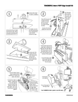
NAM and TAM Module Installation
To install the NAM and TAM modules perform the following steps:
Install the NAM module in the Student monitors/cart remove the back panel of the cart by using the key (provided
with the cart) and pushing on the lock.
1. Remove the back panel
2. Unscrew the thumbscrew on the top shelf.
3. Slide the NAM module into the top shelf.
4. Lock down the NAM module by replacing the thumbscrew.
Note: If the system is configured with an Instructor monitor/cart, install the NAM module using
the above steps.
5. Install the TAM module in the either the Instructor podium or Student monitors/cart remove the back panel of
the cart by using the key (provided with the cart) and pushing on the lock.
6. Remove the back panel
7. Unscrew the thumbscrew on the top shelf.
8. Slide the TAM module into the bottom shelf.
9. Lock down the TAM module be replacing the thumbscrew.
Note: If you have the
Educator/Tutor Extended
Height Cart (EHC-03),
refer to Appendix 3 at the
end of this manual.
Educator/Tutor Extended
Height Cart (EHC-03)

TANDBERG Educator
2
Installation and Configuration Manual - D50103-06 15
1. Connect the TAM’s power cord from the TAM’s AC input socket to a suitable wall outlet.
2. If required, a power bar may be connected to the switched AC outlet of the TAM to provide switched power for
peripheral equipment.
Cabling
System cables are connected at the rear of the TAM, either directly to the Codec or to the interface panel. Connect
cables to the TAM as required. Coil any excess lengths of cable and place at the bottom of the carts.

TANDBERG Educator
2
16 Installation and Configuration Manual - D50103-06
Cabling Configurations
Figure 3 shows the system cabling when the TAM is located in the Instructor podium.
Figure 4 shows the system cabling when the TAM is located in the Student cart. In this case, the AC power to the
student peripherals is not controlled by a power control unit, but instead the AC power is connected to a power bar
that is connected to the switched outlet of the TAM.
Touch Panel
Place the touch panel where it will be used such as on the instructor desk. Connect the touch panel cable to the
TOUCH PANEL connector on the TAM interface panel.
Student Monitors/Carts
Instructor Desk/
Podium
Optional
Peripheral
Equipment
Cart
Instructor Monitor/Cart
Instructor
Touch Panel
Figure 4 TAM Located in Student Cart
Figure 3 TAM Located in Instructor Desk/
Podium
Student Monitors/Carts
Instructor Desk/
Podium
Optional
Peripheral
Equipment
Cart
Instructor Monitor/Cart
Student
Touch Panel
Instructor

TANDBERG Educator
2
Installation and Configuration Manual - D50103-06 17
Instructor
1. Connect the INSTRUCTOR cable to the INSTRUCTOR connector on the TAM interface panel. If the TAM is not
located close enough to the equipment, use a TANDBERG T510 extension cable.
2. Route the instructor cables to the instructor equipment and connect as follows:
i) Connect the cable labeled CAM VID OUT to the VIDEO
output connector of the camera.
ii) Connect the cable labeled CAM VISCA IN to the VISCA
IN control connector of the camera.
iii) Connect the cable labeled MOTION MON VID IN to the
VIDEO input of the monitor.
iv) Connect the cable labeled GRAPHIC MON VID IN to the
VIDEO input of the monitor, if equipped.
v) Connect the cable labeled TAM AUD IN to the AUDIO
input of the Natural Audio module or other suitable
amplified speaker.
vi) Connect the cable labeled PWR CTRL to the control input
of the power control unit. (North America only)
3. Plug the power cord of the instructor cart into a suitable
wall outlet. Connect a power bar to the power output of the
control unit. Use the power bar to power the instructor
equipment.
4. Connect the camera’s power cord from the DC IN 13.5V
power socket of the camera to the instructor power bar.
5. Plug the monitor’s power cord into the instructor power bar.
Note: If you have the
Educator/Tutor Extended
Height Cart (EHC-03),
refer to Appendix 3 at the
end of this manual.
Educator/Tutor Extended
Height Cart (EHC-03)

TANDBERG Educator
2
18 Installation and Configuration Manual - D50103-06
Student
1. Connect the STUDENT cable to the STUDENT connector on the TAM interface panel. If the TAM is not located
close enough to the equipment, use a TANDBERG T510 extension cable.
2. Route the student cables to the student equipment and connect as follows:
i) Connect the cable labeled WAVE CAM to the WAVE camera.
ii) Connect the cable labeled MOTION MON VID IN to the VIDEO input of
the “motion” monitor, the monitor which will be displaying images from
the remote site.
iii) Connect the cable labeled GRAPHIC MON VID IN to the VIDEO input
of the “graphic” monitor, the monitor which will be displaying images
from local sources.
iv) Connect the cable labeled TAM AUD IN to the AUDIO input of the
Natural Audio module or other suitable amplified speaker.
v) Connect the cable labeled PWR CTRL to the control input of the power
control unit. (North America only)
Note: When the TAM is located in the student cart, the power control
unit is not used. In this case, peripherals are powered from a
power bar that is connected to the switched outlet of the TAM.
3. Plug the power cord of the power control unit into a suitable wall outlet.
Connect a power bar to the power output of the control unit. Use this
power bar to power the student equipment.
4. Connect the camera’s power cord to the student power bar. Use the
power adapter cable supplied with the system for the wave camera.
5. Plug the power cords of both monitors into the student power bar.
Note: If you have the
Educator/Tutor Extended
Height Cart (EHC-03),
refer to Appendix 3 at the
end of this manual.
Educator/Tutor Extended
Height Cart (EHC-03)

TANDBERG Educator
2
Installation and Configuration Manual - D50103-06 19
AudioScience Microphone
1. See
Appendix 1: AudioScience Microphone.
2. Connect the AudioScience microphone cable to MIC 2 on the rear of the Codec.
3. An additional AudioScience microphone may be connected to MIC 3 on the rear of the Codec.
4. Set the Audio Input level in the “ Audio Setup Page”. A 19.5dB is a good nominal value.
Network
Connect the network cables that are applicable to the site. Refer to the VISION 6000 User Manual for more
information concerning other network equipment that may be required such as network terminating units and CSUs.
ISDN BRI
Connect each cable (labeled 1 to 6) within the ISDN BRI cable loom to the ISDN BRI sockets on the Codec. Then
connect the other end of the loom to the appropriate wall sockets. If however, the wall sockets provide an ISDN U-
interface, the ISDN lines from the Codec must first be connected to the S/T interface of network terminating units NT1
and NT384. Then connect the U interface of the network terminating units to the wall sockets.
ISDN E1/T1
Connect the E1/T1 cable to the E1/T1 socket labeled “1” on the Codec. Connect the other end of the cable to a
Channel Service Unit (CSU). Then connect the CSU to the site’s E1/T1 line.
External Network
Connect an RS366/V35/RS449 or X21 cable from NET on the Codec to CSU #1. Connect the CSUs to the
appropriate wall sockets.
Ethernet
Connect the LAN cable from the Ethernet connector on the rear of the Codec to the site’s Ethernet network
connection.
Note: For instruction concerning interface configuration, see: Ethernet Diagnostic Setup.

TANDBERG Educator
2
20 Installation and Configuration Manual - D50103-06
Network Terminating Units NT1 and NT384 (North America only)
Install network terminating units when the site’s network provider ISDN BRI lines provides a U interface.
The U interface of the unit is connected to the outside network, and the S/T interface of the unit is connected to the
internal system network (Codec ISDN BRI connectors). The status of the ISDN lines can be determined by examining
the color-coded lamps that are on the font panel of each unit.
NT1
Lamp Indicates that:
U ACTIVE The outside line is available for use. (The U interface has been acquired.) This lamp may take up to 30 seconds to light.
S/T ACTIVE The internal ISDN equipment is ready. (The S/T interface has been acquired.)
NOT READY There is a problem with the U or S/T interface and it is not ready for data transmission. If this lamp remains lit, check
cabling and network connections.
NT384 (ISDN Lines 1, 2, and 3)
Lamp Indicates that:
Green The U and S/T interfaces are ready.
Orange The U interface is ready, but the S/T interface is not ready.
Red The U interface is not ready (therefore, the S/T interface is also not ready).
Network terminating unit model NT1 has two switches for configuration. These switches are factory set to the
configuration required by the Educator
2
as follows:
S/T TERM (OHMS) is set to “100”
S/T WIRING is set to “LONG”
Installing Optional Equipment
The following installation procedures apply to specific models or types of optional equipment. If you are installing
equipment other than those described, consult the documentation supplied with that equipment.
Optional equipment must be enabled on the Equipment Setup page.
WARNING: Peripheral equipment may be powered from the switched power outlet on the TAM, provided that the 6A
rating of the TAM is not exceeded.
/