Page is loading ...

Sargent Electrical Services Ltd. Copyright 2002
Issue 1 Page 1 of 1 21 October 2002
1 EC325 Control Panel Replacement
1.1 Installation Process
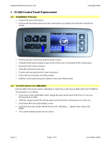
• Unpack the new control panel.
• Remove the decorative bezel from the control panel, by pulling in the direction of the BLUE
arrows.
• Remove the two screws that hold the panel in place.
• Carefully lift the panel forward to gain access to the rear circuit board of the control panel.
• Disconnect the 20-way connector and the 2-way temperature probe connector.
• Place the old panel to one side.
• Connect the new panel to the 20-way and 2-way connectors.
• Check that all connectors are firmly seated.
• Refit the control panel using the original screws and refit the bezel.
1.2 Current sensor re-calibration
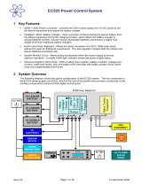
Each EC325 control panel needs 'calibrating' to match the current sensor fitted within the EC325PSU.
The procedure is as follows:
• If you have a solar panel fitted, either unplug the panel at the base of the PSU or carry out
this procedure at night.
• With the charger turned off, and the power turned off at the control panel (no LED’s on)
• Scroll down ▼ the display until battery current is shown
• Hold down the select button ◄ (left arrow) until 'calibrating….' appears; keep the button
pressed until the battery current reading re-appears.
• Now repeat the process to store the calibration reading.
• Hold down the select button ◄ (left arrow) until 'calibrating….' appears; keep the button
pressed until the battery current reading re-appears.
• The current reading should now be correct.
Note: After calibration, the panel will display 0.1 Amp with the LCD backlight on, this will drop to
0.0 Amp when the backlight turns off.
PDF created with pdfFactory Pro trial version www.pdffactory.com
/