Page is loading ...

Operation
Manual
PC Software for Torque
Sensors and Evaluation
Units
SensorTool
Type 4706A
Version from 1.3.36
4706A_002-426e-02.17

Foreword
4706A_002-426e-02.17 Page 1
Foreword
This manual refers to the PC program SensorTool Type
4706A for torque sensors and evaluation units.
Keep this system description for future reference. It should
be available at the point of use.
Information in this system description is subject to change
at any time, without notice. Kistler reserves the right to
improve and modify its products in the course of technical
advancement, without any obligation to inform any
persons or organizations of such changes.
Original language of this System description: German
©2008 ... 2017 Kistler Group. All rights reserved.
Kistler Group
Eulachstrasse 22
8408 Winterthur
Switzerland
phone +41 52 224 11 11
fax +41 52 224 14 14
www.kistler.com

ForewordTable of Contents
Page 2 4706A_002-426e-02.17
Table of Contents
1.Introduction ................................................................................................................................... 3
1.1Features ............................................................................................................................... 4
1.2Tips on using the Operation Manual .................................................................................... 4
1.3Nomenclature Used .............................................................................................................. 5
2.Basics ............................................................................................................................................. 6
2.1System Requirements ........................................................................................................... 6
3.Software Installation ...................................................................................................................... 7
3.1USB Driver Files .................................................................................................................... 8
4.Software Functions ........................................................................................................................ 9
4.1Starting the Software ........................................................................................................... 9
4.2Menu Bar ............................................................................................................................. 9
4.3Connect or Disconnect ....................................................................................................... 11
4.3.1Connection Examples ............................................................................................ 12
4.4Description of General Windows ........................................................................................ 16
4.4.1Online Display ....................................................................................................... 17
4.4.2Diagram ................................................................................................................ 19
4.4.3Analog Display ...................................................................................................... 22
4.4.4Command Console ................................................................................................ 22
4.4.5Error Messages ...................................................................................................... 23
4.4.6Digital Input/Output States ................................................................................... 24
4.4.7Communication Tester .......................................................................................... 24
4.5Communication Mode Demo ............................................................................................. 24
4.6Torque Sensor Type 4503A... ............................................................................................. 25
4.6.1Modified Online Display ........................................................................................ 26
4.6.2Type 4503A… Information ................................................................................... 27
4.7Torque Sensor Type 4503B… ............................................................................................. 28
4.8Torque Measuring Flange Type 4504B..., Type 4510B… ................................................... 29
4.8.1Modified Online Display ........................................................................................ 29
4.8.2Type 4504B… Information .................................................................................... 32
4.9Torque Measuring Flange Type 4550A... with KiTorq Stator 4541A… ............................... 32
4.9.1Modified Online Display ........................................................................................ 33
4.9.2Settings ................................................................................................................. 34
4.9.3Type 4550A…/4551A… (454xA…) Rotation Angle Options ................................ 37
4.9.4Type 455xA… (454xA…) Information .................................................................. 38
4.10Type 455xA… with KiTorq Stator Type 4542A… ............................................................... 39
4.11Evaluation Unit for Torque Sensors Type 4700B... .............................................................. 40
4.11.1Modified Online Display ........................................................................................ 40
4.11.2Type 4700B… Settings .......................................................................................... 41
4.11.3Type 4700B… Diagram ......................................................................................... 45
4.11.4Type 4700B… Remote .......................................................................................... 46
5.Summary of Screen Contents ....................................................................................................... 47
6.Index ............................................................................................................................................ 50
Total pages 53

Introduction
4706A_002-426e-02.17 Page 3
1. Introduction
We thank you for choosing a Kistler quality product. Please
read through this Operating Manual carefully in order to
make best use of the versatile features of your product.
The product is the PC program SensorTool Type 4706A for
torque sensors and evaluation units.
It enables torque sensors and evaluation units to be read
out and parameterized. Torque sensors of Type 4503...,
4504B..., 4510B… and 455xA… as well as the evaluation
units Type 4700B... and 4703B can be connected. For
presentation and demonstration purposes it is possible to
connect a “demo” object (virtual sensor) in order to get to
know the benefits of the software better.
Apart from setting the parameters, measured variables can
also be displayed online and recorded. An export of these
data in Excel, image or text format is also possible.
In order to achieve the best possible user comfort, the user
interface can be adapted to your needs by Drag & Drop. It
is thereby possible to save settings in up to three
configurations. The standard view can be restored at any
time.

ForewordTable of Contents
Page 4 4706A_002-426e-02.17
1.1 Features
Supports torque sensors Type 4503...
Supports torque measuring flanges Type 4504B..., Type
4510B…
Torque measuring flange KiTorq Rotor Type 455xA… in
combination with evaluation unit KiTorq Stator Type
454xA… .
Automatic detection of the evaluation units CoMo
Torque Type 4700B… and Strain Gage Meter Type
4703B
Automatic detection of the connected unit or sensor, of
the interface in use and the connection speed
Supports demo object for getting in touch with the
software without interfaced unit or sensor
Easy to use and freely adaptable user interface
User-defined settings can be stored in up to 3
configurations
Digital and analog display of the available measured
variables
Measured value acquisition and recording with up to
100 Hz
Data export as Excel, image or text file
1.2 Tips on using the Operation Manual
We recommend that you always read the whole operation
manual.
Keep this operation manual in a secure location where it is
available at all times. If the manual is lost, please contact
the responsible Kistler Sales company or representative and
ask for a replacement.
Software updates generally lead to changes also in the
operation manual. In this case, ask your responsible Kistler
Sales company or representative and about the update
possibilities for your documentation.

Introduction
4706A_002-426e-02.17 Page 5
1.3 Nomenclature Used
Here you will find explanations of the nomenclature and
abbreviations used in this operation manual:
GUI Graphical User Interface stands for the
graphical user interface.
Dock Area Areas of the screen where the windows
can be positioned.
Sensor The torque sensor connected to the
SensorTool Type 4706A.
Measuring Flange The torque measuring flange connec-
ted to SensorTool Type 4706A .

ForewordTable of Contents
Page 6 4706A_002-426e-02.17
2. Basics
The PC program SensorTool Type 4706A can establish a
connection to the following torque sensors and evaluation
units:
Torque measuring flange Type 455xA… with
torque evaluation unit KiTorq Stator Type
4541A… or Type 4542A…
Torque measuring flange Type 4510B…
Torque measuring flange Type 4504B…
Torque sensor Type 4503…
Evaluation unit Strain Gage Meter Typ 4703B
Evaluation unit CoMo Torque Type 4700B…
Demo measurement object for presentation
purposes
All parameters can be read out, displayed and modified
with the SensorTool Type 4706A.
Apart from the digital and analog display of the respective
measured values, the values can also be recorded at up to
100 Hz. The measurement data can be exported in Excel,
image and text format.
The user interface can be freely adapted by the user. The
desired view for the respective connected torque sensors
and evaluation units can be set in up to three different
configurations. Switching back to the standard
configuration is easily possible at any time.
2.1 System Requirements
Pentium-PC 1 GHz or higher
Windows 2000, XP, Vista or Windows 7
.Net Framework 2.0, is installed during the
installation procedure, if necessary
At least 20 MB free hard disk memory space for
the software installation
At least 128 MB RAM
RS-232C interface (for torque sensors)
USB port
SVGA monitor, resolution 800x600 or higher
Microsoft-compatible mouse

Software Installation
4706A_002-426e-02.17 Page 7
3. Software Installation
As soon as the file “setup.exe” on the enclosed installation
CD is started, the installation assistant shown on the left is
displayed. This is displayed in English and guides you
through the installation process for the SensorTool Type
4706A. Click the button “Next >” to continue.
In the next input menu it is possible to specify a folder in
which the PC program is to be installed. The button
“Browse...” allows you to look for a different directory,
clicking “Disk Cost...” displays the available space on the
hard disk for each of the individual drives.
Finally you select whether the program is to be used by
every PC user (“Everyone”) or by just one user (“Just
me”).
The inputs made are confirmed with the button “Next >”.
Clicking “Cancel” aborts the installation, click “< Back” to
go back to the previous input menu.
Click the button “Next >” to start the installation process.
The progress bar appears during the installation of the
SensorTool Type 4706A.
When the SensorTool has been successfully installed, the
installation assistant can be closed by clicking on the
button “Close”.

ForewordTable of Contents
Page 8 4706A_002-426e-02.17
3.1 USB Driver Files
The USB driver files are required when using the evaluation
unit Type 4700B… if the connection is to be made via the
USB interface.
A corresponding directory in which the USB driver files are
located is created only after installation of the SensorTool
Type 4706A PC program. If available, the USB driver can
also be installed from the installation CD (Article No.:
18025770).
The USB driver is installed e.g. automatically after
connection of the evaluation unit CoMo Torque Type
4700B… to the PC using the USB cable.
Windows will then display a prompt for the installation of
the driver.
The program directory of the PC program or the USB driver
directory of the installations CD is proposed as the manual
search location.
Windows will eventually do the driver installation twice in
order to fully establish the physical interfaces.

Software Functions
4706A_002-426e-02.17 Page 9
4. Software Functions
4.1 Starting the Software
After successful software installation, the program can be
started by the desktop icon “SensorTool” or with the
Start menu item (Start Programs Kistler
SensorTool).
4.2 Menu Bar
The menu bar of the PC program has the following
structure:
File Exit
Terminates the PC program. If a connection had been set
up to an evaluation unit or sensor, this is disconnected
before quitting the SensorTool Type 4706A.
Settings Language
Language settings in German or English. These settings
remain stored even after quitting the PC program.
Settings View…
The standard view can be restored, and the currently set
view can be stored and loaded at any time in up to 3 user
configurations.
Window Add Analog Display
An analog measuring instrument for the measured values is
added.
Window Add Console
ASCII commands can be transmitted manually to an
evaluation unit or sensor in the added console.

ForewordTable of Contents
Page 10 4706A_002-426e-02.17
Window Add Error Messages
A window with information and error messages concerning
the interface communication is displayed.
Window Add Digital In-/Outputs
A window is displayed visualizing the digital inputs and
outputs. This option is available only when a connection
has been made to an evaluation unit Type 4700B….
Help Info about SensorTool Type 4706
This menu item allows the version information on the PC
program to be displayed.

Software Functions
4706A_002-426e-02.17 Page 11
4.3 Connect or Disconnect
When SensorTool Type 4706A has been started, the
connection mask appears.
By selecting the connection port to which the torque
sensor or evaluation unit is connected, the customer can
chose between “Communication Port”, USB or Ethernet /
TCP/IP with the right IP address (as far as known). A
connection can be set up by clicking the button
“Connect”.
If the connection is not successful, a message is displayed
that no supported measuring system is connected to the
selected communication port or that the port is already in
use for another application.
When a connection has been successfully established, the
respective new window content appears automatically. In
the connection mask, the connected sensor or evaluation
unit is shown graphically and the status display changes
from “Disconnected” to “Connected”.
Clicking the button “Disconnect” disconnects the
connection again.
Automatic detection
If the type of connection is not known at COM port
(e.g. COM 1-x ), an automatic detection can be carried
out with the communication port option “Auto”.
SensorTool checks all available ports for a suitable
connection and sets up the connection automatically.
In order to test SensorTool Type 4706A without actually
connecting a sensor or evaluation unit, the option “Demo”
can be selected as the choice of communication port.
A virtual connection is then established to a demo
measurement object that emulates a torque value and a
temperature value.

ForewordTable of Contents
Page 12 4706A_002-426e-02.17
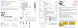
4.3.1 Connection Examples
Torque sensor Type 4503A…
The connection to a torque sensor Type 4503B… with
RS-232C option is done via the RS-232C interface
(connection to 7 pin plug of the sensor). The cable with the
order number KSM214680-5 can be used for this.
Torque sensor Type 4503B...
The connection to a torque sensor Type 4503B…is done
via the RS-232C interface (connection to 7 pin plug of the
sensor) or a USB connection.
Torque measuring flange Type 4504B…
The connection to a torque measuring flange Type
4504A… is done via the RS-232C interface (connection to
plug B of the sensor). The cable with the order number
KSM214680-5 can be used for this.
Tor
q
ue senso
r
Type 4503A…
PC program
SensorTool Type 4706A
RS-232C
7
p
in jack 9
p
in SUB-D KSM214680-5
Tor
q
ue Senso
r
Type 4503B…
PC program
SensorTool Type 4706A
USB
7
p
in jack 9
p
in SUB-D KSM214680-5/RS-232C
Tor
q
ue measuring flange
Type 4504B…
PC
p
rogram
SensorTool Type 4706A
RS-232C
7
p
in jack 9-
p
in D-SUB KSM214680-5

Software Functions
4706A_002-426e-02.17 Page 13
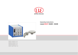
Torque measuring flange Type 4510B…
The connection to a torque measuring flange Type
4510B… is done via the RS-232C interface (connection to
the 7 pin plug of the sensor). The cable with the order
number KSM214680-5 can be used for this.
Torque measuring flange KiTorq Rotor Type 455xA…
with evaluation unit KiTorq Stator Type 454xA…
The connection with a torque measuring flange Type
455xA… is done via the torque evaluation unit Type
454xA… (Stator) with the USB or RS-232C interface. For
USB the cable with the order number KSM037856 may be
used.
Strain Gage Meter Type 4703B
The connection with the measuring unit Strain Gage Meter
Type 4703B is done via USB interface. For USB the cable
with the order number KSM037856 may be used. This
cable is also in the scope of delivery of the unit.
Tor
q
ue measuring flange
Type 4510B…
PC
p
rogram
SensorTool Type 4706A
RS-232C
7 pin jack 9 pin D-SUB
KSM214680-5
Tor
q
ue measuring flange
KiTorq Rotor Type 455xA…
wit evaluation unit KiTorq
Stator Type 454xA…
PC
p
rogram
SensorTool Type 4706A…
USB (KSM037856) or RS-232C
or TCP/IP (KSM040970)
USB (Ty
p
e Mini-B) o
r
Ethernet (TCP/IP) USB (Ty
p
A) or TCP/IP
Evaluation unit Strain
Gage Meter Type
4703B
PC
p
rogram
SensorTool Type 4706A
USB
KSM037856
USB (Ty
p
Mini-B)
USB (Typ A)

ForewordTable of Contents
Page 14 4706A_002-426e-02.17
CoMo Torque Type 4700B…
The connection to an evaluation unit CoMo Torque Type
4700B… is made via the USB or RS-232C interface. The
cables with the order numbers KSM030552 for USB or
KSM009720 for RS-232C can be used for this. Both cables
are included in the scope of delivery of the CoMo Torque
Type 4700B…
Evaluation uni
t
Type 4700B…
PC
p
rogram
SensorTool Type 4706A
or RS-232C (KSM009720)
USB (KSM030552)

Software Functions
4706A_002-426e-02.17 Page 15
USB driver
A USB driver is required for the USB connection. This
driver can be found in the installation directory of the
SensorTool Type 4706A PC program or on the CD
(Article no. KSM 026397) of the evaluation unit Type
4700B…
Connection of the active evaluation unit to the PC using
the USB cable automatically starts the installation of the
USB driver.
CoMo Tor
q
ue and tor
q
ue sensor in combination
A torque sensor Type 4501A… to 4504B… can
naturally be first connected to the evaluation unit
CoMo Torque Type 4700B… and the interface
connection to the PC program made only via the
CoMo Torque.
This offers the following advantages:
Connection via USB possible
Increased online measuring rate with up to 100 Hz
Measured values can also be read off at the CoMo
Torque
All functions of the CoMo Torque are available
(Alarms, measured value memory, digital inputs /
outputs, etc.)
Evaluation uni
t
Type 4700B… PC
p
rogram
SensorTool Type 4706A
o
r
RS-232C
(KSM009720)
USB (KSM030552)
Tor
q
ue sensor
Type 4501A… to 4503B…
Torque mesuring flange
Type 4510B…, 4504B… and 455xA…

ForewordTable of Contents
Page 16 4706A_002-426e-02.17
4.4 Description of General Windows
When a connection has been established, various window
contents appear. The mask differs, depending on the
sensor or evaluation unit connected. Apart from the
generally valid windows, separate areas are displayed for
the respective connections. The window designations can
be seen from tabs that can be displayed by clicking with
the mouse.
The sensor and evaluation unit-specific windows are
explained in more detail in the later chapters.
This chapter describes the contents that are common to all
the windows. These also include, for example, the
connection mask described in the previous chapter.
The following windows can be added dynamically by the
user via the menu “Window Add” and closed again,
when necessary:
Analog display
Command console
Error messages
Digital input/output states
The windows are closed by clicking with the mouse on the
‘Close’ symbol in the top right-hand corner of the window
register.
Generally valid windows
The following windows are always displayed during a
connection and cannot be closed:
Online display (sensors and evaluation units)
Diagram (sensors and evaluation unit)
4700B… Settings (evaluation unit only)
4700B… Remote (evaluation unit only)
4503… Information (sensors only)
4504B… Information (sensors only)
4510B… Information (sensors only)
454xA…
Settings, Information (sensors only)
455xA… Information (sensors only)
Symbol for closing a window
Window activity after clicking with the mouse of
the respective tab

Software Functions
4706A_002-426e-02.17 Page 17
4.4.1 Online Display
The online display permits the digital representation of up
to three different measured variables.
The type of measured variables depends on the interfaced
sensor or evaluation unit, see following table:
Senso
r
t
yp
e Evaluation unit
Measured
variable
selectable
4503… 4504B
4510B
455xA
(454xA)
CoMo Torque
4700B
Torque x x x x
Speed x x x
Rotation
angle x x x x
Revolution
counter
reading x
Mechanical
power x x x
Rotor
tempetature x x x
In case of the evaluation unit Type 4703A… the preset
measured variable will be used.
It is possible to define the number of decimal places for the
respective measured variable. These setting options can be
found to the right of the displayed units.
The measuring rate can be set from 0,01 … 100 Hz and
indicates the frequency with which the displayed measured
values are refreshed in the SensorTool. The following table
shows the maximum refresh rates, depending on sensor
and evaluation unit and the type of connection:
Connection Max.
measuring
rate
Sensor Ty
p
e 4503… RS-232C 20 Hz
Sensor Ty
p
e 4504B… RS-232C 20 Hz
Sensor Ty
p
e 4510B… RS-232C 20 Hz
Sensor Ty
p
e 455xA… (4541A…)
RS-232C 50 Hz
Senso
r
Ty
p
e 455xA… (4541A… or
4542A…) USB or TCP/IP 100 Hz
CoMo Tor
q
ue Ty
p
e 4700A… RS-232C 50 Hz
CoMo Tor
q
ue Ty
p
e 4700A… USB 100 Hz
Strain Gage Meter Ty
p
e 4703B… USB 50 Hz

ForewordTable of Contents
Page 18 4706A_002-426e-02.17
Depending on the interfaced sensor or evaluation unit,
further input elements are displayed. The interested reader
can find further details in the respective chapters of this
operating manual. The online display is always active
during an existing connection and cannot be closed.
Measurin
g
rate at
p
ro
g
ram start
The measuring rate at the program start is defaulted to
10 Hz and can be increased or decreased manually.

Software Functions
4706A_002-426e-02.17 Page 19
4.4.2 Diagram
The diagram serves to record measuring curves. Up to 4
measured variables can be recorded over the time.
At least one measured variable must be selected before a
recording can be started. Each measured variable is
displayed with automatic scaling in the diagram window.
If the box is not checked, the user can carry out an
individual scaling. If the box is not checked, the user can
carry out an individual scaling. It is additionally possible to
have coordinate axes added. This enables the values of the
measuring curve ranges to be determined more easily.
These parameters cannot be changed during the recording
of a measured value. Recording starts as soon as the
button “Start recording” is clicked. During the
measurement, this button has a green background. Click
this button again to terminate the measurement.
Measured value recording is continued until the set
measurement time is reached. If an unlimited measurement
time has been set, the measured value recording must be
terminated again manually. The refresh rate of the diagram
can be varied.
Refresh rate of the dia
g
ram contents
The minimum refresh rate that can be set is 50 ms. This
value has no influence on the measuring rate of the
measured value transmission of the interface set in the
“online display”. If the PC system is not very powerful,
this value should be increased (e.g. to 200 ms).
Autoscaling activated
User scaling with min. and max. value
Measured variable selection
/