Page is loading ...

Quick Start Installation
Melt pressure measuring chain with ø7,8 mm sensor and
½" 20 UNF thread
Type 4021B…
1. General
• Diameter of sensor must not be machined
• Front and rim of sensor must be clean and free from
scoring
• Do not touch diaphragm on front of sensor with
sharp tool
• Only use recommended mounting tool
• Each sensor belongs to its unique charge amplifier.
Otherwise a measurement cannot be assured. Please
check: The sensor must have the same serial number
as the amplifier.
4021B_002-597e-08.20
Contents
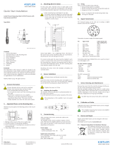
Front page: forming sensor bore
1. General
2. Important aspects of bore
3. Forming bore
4. Checking bore
4.1 Checking bore, thread and seal seat
4.2 Finishing bore
5. Mounting sensor
6. Taring measurement/operating test
6.1 Taring by means of machine control system
6.2 Taring with PIN 3 and PIN 8
Back page: servicing, taring measurement/operating test,
Kistler factory calibration, servicing and repair
7. Servicing
8. Taring measurement/operating test
9. Kistler factory calibration
10. Servicing and repair
Foreword
Information in this document is subject to change without
notice. Kistler reserves the right to change or improve its
products and make changes in the content without obligati-
on to notify any person or organization of such changes or
improvements.
To the extent permitted by law Kistler does not accept any
liability if this Quick Start Installation guide is not followed or
products other than those listed under Accessories are used.
© 2012 ... 2020 Kistler Group. All rights reserved. Kistler
Group products are protected by various intellectual property
rights. For more details visit www.kistler.com.
• Use fork wrench 13 for HA & HS versions
• Use fork wrench 19 for H0, H1 and H2 versions
Heat empty (unpressurized) nozzle up to operating tempera-
ture (>150 °C) and retighten to torque of 40 N∙m.
• If the sensor leaks, tighten to maximum of 45 N∙m
6. Taring measurement/operating test
At operating temperature (>150°C) and with nozzle empty
(unpressurized), connect sensor to measuring chain and tare:
6.1 Taring by means of machine control system
Apply voltage to tare conductor.
6.2 Taring with PIN 3 and PIN 8
Short the two pins. Pin 8 must be live for this purpose!
5. Mounting sensor
• Sensor bore and thread must be clean
• Seal must be positioned on the sensor
Apply copper paste, Molykote or high-temperature grease
sparingly to thread and sealing surface.
Screw sensor in at room temperature.
Tightening torque 40 N∙m.
• If measurement noise arises when there is a large elec-
trical potential difference between nozzle and control
unit, the shield of the cable must not be connected to
the control box
7,8
0
-0,03
3
4
9
10,05±0,01
10,5
0
-0,03
2. Important aspects of bore
Attention must be paid to the following aspects:
1. Ensure sensor centered
2. Seal seat
3. No centering bore
4. Do not mount sensor so it protrudes
A
0,1 A
1
2
3
4
3. Forming bore
Form the bore with ½" thread and seal seat as shown on the
following drawing.
Then ream bore with Ø7,94 mm ream (Mat. No. 65007827).
• Keep perpendicular and centered
max. R0.1
min.17
A
0,1 A
1/2-20UNF-2B
3,05
+0,05
0
0,5
+0,1
0
max.3
max.24
7,94
+0,05
0
11,5
+0,1
0
10,05
+0,05
0
4. Checking bore
Use the following tools to check and rework the measuring
bore:
4.1 Checking bore, thread and seal seat
The limit plug gage (Mat. No. 65000124) and fork wrench
11 (Mat. No. 65007836) are used together with Kistler grease
Type 1063 to check the bore and its perpendicularity.
• Always use Kistler grease Type 1063
4.2 Finishing bore
The Ø7,94 mm reamer (Mat. No. 65007827) can be used to
finish the bore.
Connection to supply and output signals
M12x1 industrial connector, 8-pole male
# Signal Cable Type 1787A5
wire color
1 Exct. GND white
2 Signal GNG brown
3 Tare green
4 Pressure signal 0 ... 10 V (at P1)
or 4 ... 20 mA (at P2) yellow
5 Temp. signal 10 mV/K (at P1)
or 20 μA/K (at P2) grey
6 res. pink
7 res. blue
8 +Exct. (18 ... 30 V) red
Requirements for structure material of the measuring bore
(Nozzle body)
Min. Max.
Hardness HRC 40 55
Tensile strength Mpa 1 200 1 820

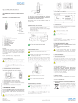
7. Servicing
The sensor has to be removed for maintenance work and
mechanical cleaning of the injection molding nozzle.
• Service kit Type 4193A contains:
Limit plug gage (Mat. No. 65000124)
Fork wrench 11 (Mat. No. 65007836)
Kistler grease Type 1063
Ø7,94 mm reamer (Mat. No. 65007827)
Screw tap (Mat. No. 65007829)
7.1 Removing sensor
Heat nozzle to operating temperature (>150 °C) before
removing sensor. The seal must remain on the sensor during
removal. If the seal ring should remain in the bore, it can be
removed with extraction tool Type 4193Q02. Before instal-
ling the sensor again a new seal ring Mat. No. 65000503 has
to be installed. For that insert the seal ring into the empty
bore concentrically to the axis. Then install and tighten the
sensor carefully.
• Check that seal is present on the sensor
• Use fork wrench 13 for HA & HS versions
• Use fork wrench 19 for H0, H1 and H2 versions
7.2 Cleaning and checking bore and thread
At ambient temperature, clean ½" thread with screw tap
(Mat. No. 65007829). Ream bore with Ø7,94 mm (Mat. No.
65007827) reamer.
• Clean with white spirit
7.3 Checking bore
Carry out visual inspection to ensure the seal has not been
left on the sealing surface in the mounting bore. Use limit
plug gage (Mat. No. 65000124), fork wrench 11 (Mat. No.
65007836) and Kistler grease Type 1063 to check bore and
thread.
• Check visually that old seal has been removed
• Do not damage seal seat
7.4 Cleaning sensor
Rub dirt and plastic residues off the hot sensor radially with
chamois leather or soft brass brush. Do not overstress the
sensitive diaphragm on the front.
• Do NOT clean front of sensor with steel brush!
9. Kistler factory calibration
Calibration and repair in the Kistler factory are arranged
through your local Kistler sales company.
• The complete measuring chain is required for cali-
bration
10. Servicing and repair
10.1 Cable repair
Damaged cable cannot be repaired. Replacement cables must
be fitted in the Kistler factory.
10.2 Repairs in Kistler factory
Repairs in the factory are arranged through your local sales
company.
Visit www.kistler.com for further information
10.3 Disposal Instructions for electrical and elec-
tronic equipment
Do not discard old electronic instruments in
municipal trash. For disposal at end of life,
please return this product to an authorized
local electronic waste disposal service or
contact the nearest Kistler Instrument sales
office for return instructions.
Apply copper paste, Molykote or high-temperature grease
sparingly to thread and sealing surface.
Screw sensor in at room temperature.
Tightening torque 40 N∙m
Kistler Group
Eulachstrasse 22
8408 Winterthur, Switzerland
Tel. +41 52 224 11 11
info@kistler.com www.kistler.com
4021B_002-597e-08.20 ©2012 ... 2020, Kistler Group
• Use fork wrench 13 for HA & HS versions
• Use fork wrench 19 for H0, H1 and H2 versions
Heat empty (unpressurized) nozzle up to operating tempera-
ture (>150 °C) and retighten to torque of 40 N∙m.
8. Taring measurement/operating test
At operating temperature (>150 °C) and with nozzle empty
(unpressurized), connect sensor to measuring chain and tare:
8.1 Taring by means of machine control system
Apply voltage to tare.
8.2 Taring with PIN 3 and PIN 8
Short the two pins. Pin 8 must be live for this purpose!
Connection to supply and output signals
M12x1 industrial connector, 8-pole male
# Signal Cable Type 1787A5
wire color
1 Exct. GND white
2 Signal GND brown
3 Tare green
4 Pressure signal 0 ... 10 V (at P1)
or 4 ... 20 mA (at P2) yellow
5 Temp. signal 10 mV/K (at P1)
or 20 μA/K (at P2) grey
6 res. pink
7 res. blue
8 +Exct. (18 ... 30 V) red
7.5 Mounting sensor
• Sensor bore and thread must be clean
• Seal must be positioned on the sensor
/
