Page is loading ...

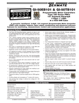
IGYZ Data Sheet (NZ343) Page 1Texmate, Inc. Tel. (760) 598-9899 • www.texmate.com
Hardware Module Specifications
Span Pot Adjust.
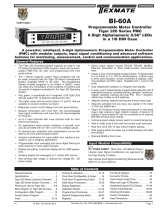
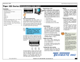
UNIVERSAL DIRECT PRESSURE SENSOR INPUT MODULE
A cost effective solution for pressure applications requiring monitoring and process control of non-corrosive,
non-ionic working fluids such as air, dry gases and similar. The pressure sensor is available in absolute and
differential models and pressure ranges from 0 to 100 psi. The input module interfaces directly with Lynx,
Leopard, and Tiger 320 Series meters.
Fits Lynx, Leopard & Tiger 320 Series
Pressure Inputs Channel 1 Absolute or differential connections
via 2.5 mm I.D. pneumatic tubing.
Pressure Ranges 0-1, 0-5, 0-15, 0-30, and 0-100 psi.
Temperature compensated 0-50 °C, ± 0.4% Full Scale.
Max Pressure any Port 150 psi.
Repeatability ± 0.2% Full Scale typical.
Linearity/Hysteresis ± 0.2% Full Scale typical.
Output Voltage ± 2 V Full Scale.
Zero Adjust Zero potentiometer.
Span Adjust Span potentiometer.
Connection.
2.5 mm I.D. pneumatic
tubing.
Ratiometric Measurement &
Differential Amplification of
Pressure Sensor Output.
Zero Pot Adjust.
On-board Sensor.
Absolute.
Differential has two connections.
Interface to Lynx, Leopard
or Tiger 320 Meter.
PRESSURE
INPUTS
An on-board pressure sensor module for Texmate's range of modular meters.
Not available
Sensor Range CH1
Not available
15 psi absolute
30 psi absolute
100 psi absolute
1 psi differential
5 psi differential
15 psi differential
30 psi differential
100 psi differential
A
B
C
D
E
F
G
H
J
K
I G Z
For example, IGDZ:
CH1 5 psi, differential pressure.
The last digit of the
order code is always Z.
IGYZ
Input Module
Order Code Suffix

Texmate, Inc. Tel. (760) 598-9899 • www.texmate.comPage 2 IGYZ Data Sheet (NZ343)
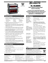
ZERO
332
SINGLE or
DIFFERENTIAL
PRESSURE
INPUT
(CH1)
SPAN
AB
SO
L
U
T
E
PRE
SSU
R
E
INP
UT
(
CH1
)
AB
SO
L
U
TE
S
EN
SOR
DIFFERENTIAL
S
EN
SOR
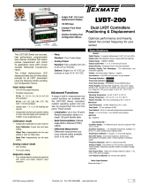
Connector Pinouts
Figure 1 – IGYZ Universal Direct Pressure Sensor Input Module Component La yout
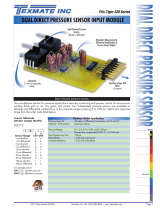
Detailed Description
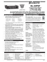
Figure 2 – IGYZ Universal Direct Pressure Sensor Input Module Signal Flo w Diagram
SINGLE or
DIFFERENTIAL
PRESSURE
INPUT to CH1
Pressure
S
enso
r
Amplifier
CH1
ZERO
Offset
Multiplier
This module interfaces directly with Texmate’s Tiger, Leopard, and Lynx range of modular con-
trollers and panel meters . It has a single output that is an amplified and scaled v ersion of the
onboard direct pressure sensor.
The sensor can be ordered as either an absolute or diff erential pressure type . Gain setting
resistors are factory installed to optimize the full scale output for each pressure range.
Contact Texmate when ordering to discuss your pressure range requirements.
Tiger Controllers and Leopard Meter Relays
The Tiger and Leopard range use internal software functions to calibrate the span and zero off-
set. However, it may be necessary to adjust the span potentiometer to bring the maximum input
signal within the full scale r ange of the instr ument. The Lynx has no inter nal software calibra-
tion procedure. Calibration is done manually using both the zero and span potentiometers.

IGYZ Data Sheet (NZ343) Page 3Texmate, Inc. Tel. (760) 598-9899 • www.texmate.com
Prog. SP1 SP2 SP3 SP4 SP5 SP6
Prog.
SP3 SP4
SP2SP1
Example: TIGER DI-50
Example: LEOPARD DL-40
Overrange Indications
Figure 3 – Overrange Indications
Lynx
When the input signal is be yond the full scale r ange of a L ynx
meter, all the segments of each digit of the displa y flashes.
Leopard
When the input signal is be yond the full scale r ange of a Leopard
meter, the top segment of each digit on the displa y flashes. See
Figure 3.
Tiger
When the input signal is be yond the full scale r ange of a Tiger
controller, the display flashes [OVER]. See Figure 3.
332
ZER
O
S
PA
N
+
–
332
ZER
O
S
PA
N
+
–
1
2
Figure 4 – Lynx Calibration Setting
Lynx Indicators
Lynx indicators are supplied to match the displa yed
full scale counts to the full scale input pressure .
Lynx indicators can displa y the f ollowing resolution
for absolute and differential pressure ranges:
Pressure Range Full Scale Display Counts
Absolute Differential
1 psi
5 psi
15 psi
30 psi
100 psi
Not available
Not available
15.00
30.0
100.0
± 1.00
± 5.00
± 15.00
± 30.0
± 100.0
Lynx Calibration Example
See Figure 4. For a certain application, a
15 psi pressure input may be required to
read ± 2.00 counts on the meter displa y.
Apply a zero pressure input or zero pres-
sure diff erential. Using the z ero poten-
tiometer, adjust the zero pot until the dis-
play reads 0 counts.
Now apply the full scale pressure signal
of 15 psi. Using the span potentiometer ,
adjust the span pot until the displa y
reads 2.00 counts.
This procedure can be used to calibr ate
a L ynx o ver an y of the specified input
ranges b y adjusting the full scale pres-
sure signal and the full scale displa y
counts to suit.
Leopard & Tiger Initial Setup
If an overrange condition exists, with the full
scale pressure applied to the pressure sen-
sor, tur n the 15-tur n span potentiometer
counter-clockwise to decrease the signal
until a reading appears on the display (See
Figure 5). Now calibr ate the instr ument
using the softw are calibr ation method f or
your instr ument. See Leopard Calibr ation
Example on P age 4 and Tiger Calibr ation
Example on Page 6.
332
ZER
O
S
PA
N
+
–
Figure 5 – Leopard & Tiger Initial Calibration Setting

Texmate, Inc. Tel. (760) 598-9899 • www.texmate.comPage 4 IGYZ Data Sheet (NZ343)
Leopard Meter Relay Calibration Example
In the following example, compressed air is supplied at a constant 80 psi to the pneumatics of
an assembly line. If the air pressure becomes greater than 90 psi for an extended period dam-
age can occur to the pneumatic seals .
A Leopard DL-40 meter relay has been installed to monitor the air with an IGYZ universal direct
pressure input module set to 100 psi absolute pressure . A setpoint activ ates if the pressure
exceeds 90 psi for more than 10 seconds, opens a relief valve, and sounds an alar m.
Procedure
With the compressor off and the air lines open, set the meter ’s zero calibration setting.
With the isolation v alve closed and only the sample pressure line open, star t the compressor
and take it to 100 psi. With 100 psi at the meter, set the meter’s span (full scale) setting.
The following example calibration procedure demonstrates calibrating the Leopard DL-40 meter
with a zero setting of 0 counts, and a span (full scale) setting of 100 psi. See Figure 7 and the
calibration procedure diagram opposite.
The high input source is
applied to the meter when
setting the span value.
0
Full
Scale
0
Full
Scale
Prog.
SP3 SP4
SP2SP1
Prog.
SP3 SP4
SP2SP1
Figure 7 – Leopard 2-point Calibration Zero and Span Setting
The low input source is applied
to the meter when setting the
zero value.
Figure 6 – IGYZ Universal Direct Pressure Sensor Leopard Calibration Example
Prog.
SP3 SP4
SP2SP1
Alarm
Sample
Pressure
Line
80 psi
Leopard DL-40
Setpoint
Control
To
Assembly
Line
Relief Valve
Blow off
Isolation
Valve

IGYZ Data Sheet (NZ343) Page 5Texmate, Inc. Tel. (760) 598-9899 • www.texmate.com
To Step 10
From Step 9
6.2. Apply the LOW (ZEro)
input pressure
(e.g 0 psi)
Step 1
Step 2
Step 3
Step 4
Step 5
Step 6
Step 10
Step 11
Step 12
Step 13
Step 14
Enter the Calibration
Mode
Select calibration [on]
Set the display to the
required brightness
If an analog output is
installed, enter the analog
output digital HIGH span
range setting mode
Operational Display
Set the display counts you
want to see for the analog
output HIGH span setting
Select calibrate [iP]
Select [iP]
Select the required
decimal point setting
(e.g. XXX.X)
Enter the span mode
Enter the brightness
setting mode
Example
Note: If there is no
analog output installed
the meter goes directly
to the zero input setting
mode (Step 6).
0
Full
Scale
0
Full
Scale
Prog.
SP3 SP4
SP2SP1
Press
at same
time
Press
at same
time
Prog.
SP3 SP4
SP2SP1
Prog.
SP3 SP4
SP2SP1
OR
Prog.
SP3 SP4
SP2SP1
Press
1
Prog.
SP3 SP4
SP2SP1
Prog.
SP3 SP4
SP2SP1
OR
Prog.
SP3 SP4
SP2SP1
Press
1
Prog.
SP3 SP4
SP2SP1
Prog.
SP3 SP4
SP2SP1
OR
Prog.
SP3 SP4
SP2SP1
Press
1
Prog.
SP3 SP4
SP2SP1
Prog.
SP3 SP4
SP2SP1
OR
Prog.
SP3 SP4
SP2SP1
Prog.
SP3 SP4
SP2SP1
Press
1
OR
Prog.
SP3 SP4
SP2SP1
Press
1
Prog.
SP3 SP4
SP2SP1
Prog.
SP3 SP4
SP2SP1
OR
Example
Prog.
SP3 SP4
SP2SP1
Press
1
Prog.
SP3 SP4
SP2SP1
Prog.
SP3 SP4
SP2SP1
OR
Example
Prog.
SP3 SP4
SP2SP1
Press
1
Prog.
SP3 SP4
SP2SP1
Prog.
SP3 SP4
SP2SP1
OR
Example
Prog.
SP3 SP4
SP2SP1
Press
1
Prog.
SP3 SP4
SP2SP1
Operational Display
Enter the next phase
of the Calibration
Mode
This bypasses the analog
output range setting and
calibration menu and selects
the input 2-point calibration
menu
6.1. Adjust the display
to the desired reading for
the zero input setting
Step 7
Enter the decimal
point setting mode
Step 8
8.2. Apply the HIGH
(SPAn) input pressure
(e.g. 100 psi)
Step 9
8.1. Adjust the display to
the desired reading for
the span input setting
Example
Decimal point settings:
X XXX
XX XX
XXX X
XXXX
XXXX
Display brightness settings:
1 (Dull)
2
3
4 (Bright)
Note: If there is no
analog output installed,
the calibration settings
are saved and the meter
goes directly back to the
operational display.
See Step 17.
Step 15
Enter the analog output
digital LOW span range
setting mode
Step 16
Set the display counts you
want to see for the analog
output LOW span setting
Step 17
Save the caliration
settings and return to
the operational display
ST
STAR
ART HERE
T HERE

Texmate, Inc. Tel. (760) 598-9899 • www.texmate.comPage 6 IGYZ Data Sheet (NZ343)
Procedure
Without the filter in place, zero channel 1.
Now apply 15 psi into the positive (+) differential input tube, while leaving the negative (–) input
tube open to atmosphere.
The following example calibr ation procedure demonstr ates calibr ating the Tiger DI-50 meter
with a zero setting of 0 counts, and a span (full scale) setting of 1500 counts for 15 psi on chan-
nel 1 (CH1). See Figure 9 and the calibr ation procedure diagram opposite.
The high input source is
applied to the meter when
setting the span value.
Programming Tip
All displays shown in this example are for a 5-digit, 7-segment
display. Using any other display type in the Tiger 320 Series
range will look slightly different.
Prog.
SP1 SP2 SP4SP3 SP5 SP6
Prog.
SP1 SP2 SP4SP3 SP5 SP6
0
Full
Scale
0
Full
Scale
Figure 9 – Tiger 2-point Calibration Zero and Span Setting
The low input source is
applied to the meter when
setting the zero value.
Tiger Controller Calibration Example
In the following example, a Tiger 320 Series controller has been installed with an IGYZ univ er-
sal direct pressure input module set to 15 psi differential pressure to monitor the efficiency of a
filter mounted in an air duct.If the differential pressure becomes too great, the controller sounds
an alarm. See Figure 8.
Figure 8 – IGYZ Universal Direct Pressure Sensor Tiger Calibration Example
Prog.
SP1 SP2 SP4SP3 SP5 SP6
Alarm
Air Flow
–
+
Filter
Reduced Flow

IGYZ Data Sheet (NZ343) Page 7Texmate, Inc. Tel. (760) 598-9899 • www.texmate.com
Prog.
SP1 SP2 SP4SP3 SP5 SP6
TEXMATE
Prog.
SP1 SP2 SP4SP3 SP5 SP6
TEXMATE
Prog.
SP1 SP2 SP4SP3 SP5 SP6
TEXMATE
Prog.
SP1 SP2 SP4SP3 SP5 SP6
TEXMATE
Prog.
SP1 SP2 SP4SP3 SP5 SP6
TEXMATE
Prog.
SP1 SP2 SP4SP3 SP5 SP6
TEXMATE
Prog.
SP1 SP2 SP4SP3 SP5 SP6
TEXMATE
Prog.
SP1 SP2 SP4SP3 SP5 SP6
TEXMATE
Prog.
SP1 SP2 SP4SP3 SP5 SP6
TEXMATE
Prog.
SP1 SP2 SP4SP3 SP5 SP6
TEXMATE
Prog.
SP1 SP2 SP4SP3 SP5 SP6
TEXMATE
Prog.
SP1 SP2 SP4SP3 SP5 SP6
TEXMATE
Prog.
SP1 SP2 SP4SP3 SP5 SP6
TEXMATE
Prog.
SP1 SP2 SP4SP3 SP5 SP6
TEXMATE
Prog.
SP1 SP2 SP4SP3 SP5 SP6
TEXMATE
X
Prog.
SP1 SP2 SP4SP3 SP5 SP6
TEXMATE
Prog.
SP1 SP2 SP4SP3 SP5 SP6
TEXMATE
To Step 7
OR
From Step 6
5.2. Apply the LOW
input pressure
OR
OR
Press
1
Press
1
Press
1
Press
1
Press
at same
time
Press
at same
time
Press
at same
time
Press
at same
time
Step 1
Step 2
Step 3
Step 4
Step 5
Step 6
7.2. Apply the HIGH
input pressure
Step 7
Step 8
Step 9
Step 10
Step 11
Enter brightness
mode
Pass brightness mode
and the enter calibration
mode
Select the no function
calibration mode [000]
Save calibration mode
[000] setting and enter
Code 1
Operational Display
Operational Display
Exit code 1 and return
to operational display
Enter calibration
mode [111] for 2-point
calibration of CH1
5.1. Adjust the display to
the desired reading for
the zero input setting
7.1. Adjust the display to
the desired reading for
the span input setting
Set the reading for
zero load into the
meter and enter the
span mode
Save the zero and the
span settings and
re-enter the calibration
mode
Example
Example
OR
Set calibration mode to [111]:
1st Digit = 1
Selects calibration procedures
2nd Digit = 1
Selects 2-point calibration
3rd Digit = 1
Selects CH1 for calibration
Prog.
SP1 SP2 SP4SP3 SP5 SP6
TEXMATE
Press
1
[111] for CH1
[112] for CH2
[113] for CH3
[114] for CH4
0
Full
Scale
0
Full
Scale
ST
STAR
ART HERE
T HERE

Texmate, Inc. Tel. (760) 598-9899 • www.texmate.comPage 8 IGYZ Data Sheet (NZ343)
WARRANTY
Texmate warrants that its products are free from def ects in mater ial and w orkmanship under
normal use and ser vice for a per iod of one y ear from date of shipment. Texmate’s obligations
under this warranty are limited to replacement or repair, at its option, at its factory, of any of the
products which shall, within the applicable period after shipment, be returned to Texmate’s facil-
ity, tr ansportation charges pre-paid, and which are , after e xamination, disclosed to the satis-
faction of Texmate to be thus def ective. The warranty shall not apply to an y equipment which
shall have been repaired or altered, except by Texmate, or which shall have been subjected to
misuse, negligence , or accident. In no case shall Texmate’s liability e xceed the or iginal pur-
chase price. The aforementioned provisions do not e xtend the original warranty period of an y
product which has been either repaired or replaced b y Texmate.
USER’S RESPONSIBILITY
We are pleased to offer suggestions on the use of our v arious products either by way of print-
ed matter or through direct contact with our sales/application engineering staff. However, since
we ha ve no control o ver the use of our products once the y are shipped, NO WARRANTY
WHETHER OF MERCHANT ABILITY, FITNESS FOR PURPOSE, OR O THERWISE is made
beyond the repair, replacement, or refund of purchase pr ice at the sole discretion of Texmate.
Users shall deter mine the suitability of the product f or the intended application bef ore using,
and the users assume all risk and liability whatsoever in connection therewith, regardless of any
of our suggestions or statements as to application or constr uction. In no event shall Texmate’s
liability, in law or otherwise, be in excess of the purchase pr ice of the product.
Texmate cannot assume responsibility for any circuitry described. No circuit patent or software
licenses are implied. Texmate reserves the right to change circuitry, operating software, speci-
fications, and prices without notice at any time.
For product details visit www.texmate.com
Tel: 1-760-598-9899 • USA 1-800-839-6283 • That’s 1-800-TEXMATE
1934 Kellogg Ave. • Carlsbad, CA 92008
Email: [email protected] • Web: www.texmate.com
/