Page is loading ...

Installation and Operating Instructions For
3MRO401 Reverse Osmosis Drinking Water
Filtration System
Installer: Please leave manual with homeowner.
Homeowner: Please retain for operation and
future maintenance instructions.
3M Clean Water Solutions

SAFETY INFORMATION
Read, understand and follow all safety information contained in these instructions prior to installation and use of
the 3MRO401 Reverse Osmosis Drinking Water Filtration System. Retain these instructions for future reference.
Intended use:
The 3MRO401 Reverse Osmosis Drinking Water Filtration System is intended for use in fi ltering drinking water in resi-
dential locations and has not been evaluated for other uses. The system is typically installed beneath a kitchen sink, and
must be installed as specifi ed in the installation instructions by a qualifi ed professional installer.
EXPLANATION OF SIGNAL WORD CONSEQUENCES
WARNING
WARNING
CAUTION
CAUTION
CAUTION
CAUTION
Indicates a potentially hazardous situation, which, if not avoided, could result in death or serious
injury and/or property damage.
Indicates a potentially hazardous situation, which, if not avoided, may result in minor or moderate
injury and/or property damage.
Indicates a potentially hazardous situation, which, if not avoided, may result in property damage.
WARNING
To reduce the risk associated with choking:
• Do not allow children under 3 years of age to have access to small parts during the installation of this product.
To reduce the risk associated with ingestion of contaminants:
• Do not use with water that is microbiologically unsafe or of unknown quality without adequate disinfection before
or after the system. Systems certifi ed for cyst reduction may be used on disinfected water that may contain fi lter-
able cysts. EPA Establishment # 070595-CT-001
To reduce the risk associated with a hazardous voltage due to an installer drilling through existing electric wiring
or water pipes in the area of installation:
• Do not install near electric wiring or piping which may be in the path of a drilling tool when selecting the position to
mount the fi lter bracket.
To reduce the risk of physical injury:
• All hydro-pneumatic pressurized tanks must have an appropriate pressure relief valve installed.
• Shut off inlet water supply and depressurize system as shown in manual prior to fi lter removal.
To reduce the risk associated with irritation from Sodium Metabisulfi te during installation:
• Sodium Metabisulfi te (CAS 007681-57-4) is used in a 1% sanitizer solution within the reverse osmosis membrane.
• Do not put this system into service before the RO tank is fl ushed as specifi ed in the installation instructions. Wear
eye and face protection during installation.
• To request an MSDS relating to this product, call 203-238-8965 or visit the web at http://solutions.3m.com/wps/
portal/3m/en_us/MSDS (click MSDS search). For emergencies, call 800-364-3577 or 651-737-6501 (24 hours).
To reduce the risk associated with eye, skin and respiratory and digestive tract burns from Calcium Hypochlorite
during installation:
• Calcium Hypochlorite (CAS 7778-54-3) granules are used for tank sanitation in this product.
• During installation, do not get in eyes or on skin or clothing. Do not ingest. Wear eye and face protection.
Keep out of reach of children.
• To request an MSDS relating to this product, call 203-238-8965 or visit the web at http://solutions.3m.com/wps/
portal/3M/en_US/MSDS (click MSDS search). For emergencies, call 800-364-3577 or 651-737-6501 (24 hours).
To reduce the risk associated with ingestion of water contaminated with sanitizer:
• After installation, sanitizers must be fl ushed from the system before fi rst use as directed within the installation
instructions.
2
To reduce the risk of eye injury while drilling countertop for faucet installations:
• Safety glasses MUST be worn during the sink hole drilling operations.
CAUTION

• Failure to install or operate your fi lter system in accordance with these use instructions or any
other installation or use instructions accompanying this product may result in product failure and
property damage, including water leakage and will void warranty.
CAUTION
To reduce the risk associated with property damage due to water leakage:
• Read and follow Use Instructions before installation and use of this system.
• Installation and Use MUST comply with all state and local plumbing codes.
• Protect from freezing, remove fi lter cartridge when temperatures are expected to drop below 40° F (4.4° C).
• Do not install systems in areas where ambient temperatures may go above 110° F (43.3° C).
• Do not install on hot water supply lines. The maximum operating water temperature of this fi lter system is 100°F
(37.8°C).
• Do not install if water pressure exceeds 100 psi (689 kPa). If your water pressure exceeds 80 psi, you must install a
pressure limiting valve. Contact a professional qualifi ed installer if you are uncertain how to check your water pressure.
• Do not install where water hammer conditions may occur. If water hammer conditions exist you must install a water
hammer arrester. Contact a professional qualifi ed installer if you are uncertain how to check for this condition.
• Where a backfl ow prevention device is installed on a water system, a device for controlling pressure due to ther-
mal expansion must be installed.
• Do not use a torch or other high temperature sources near fi lter system, replacement fi lters, plastic fi ttings or
plastic plumbing.
• On plastic fi ttings, never use pipe sealant or pipe dope. Use PTFE thread tape only, pipe dope properties may dete-
riorate plastic.
• Take care when using pliers or pipe wrenches to tighten plastic fi ttings, as damage may occur if over tightening
occurs.
• Do not install in direct sunlight or outdoors.
• Do not install near water pipes which will be in path of a drilling tool when selecting the position to mount the
bracket.
• Mount fi lter in such a position as to prevent it from being struck by other items used in the area of installation.
• Ensure that the location and fasteners will support the weight of the system when installed and full of water.
• Ensure all tubing and fi ttings are secure and free of leaks.
• Do not install unit if any fi tting collets are missing. Contact 3M if collets are missing from any fi ttings.
• All hydro-pneumatic tanks must have an appropriate pressure relief valve installed.
• The disposable replacement fi lters must be replaced every 12 months, at the rated capacity or sooner if a notice-
able reduction in fl ow rate occurs.
• The RO membrane module must be replaced every 36 months, at the rated capacity or sooner if a noticeable
reduction in fl ow rate occurs.
3

INTRODUCTION
This manual explains the installation, operation and maintenance of the 3MRO401 Reverse Osmosis Water Filtration
System. Please read each section of this manual carefully.
The RO drinking water system is designed to connect permanently to a home’s plumbing system. The installation MUST
conform to your state and local plumbing codes. Advanced plumbing skills are required to complete your installation.
Failure to install the system as instructed will VOID the warranty.
TABLE OF CONTENTS
I. Installation Instructions
A. Determine the system location ........................................................................................................5
B. Prepare the area for installation ......................................................................................................5
C. Determine faucet mounting location ...............................................................................................5
D. Make the faucet mounting hole .......................................................................................................5
E. Mount the faucet .............................................................................................................................6
F. Prepare the system for installation .................................................................................................6
G. Install the feed water connection and tubing ..................................................................................7
H. Prefill and sanitize the storage tank ................................................................................................7
I. Install the drain connection .............................................................................................................7
J. Install the filtration assembly and storage tank ...............................................................................8
K. Make the tube connections .............................................................................................................8
L. Start up the system .........................................................................................................................8
M. Flush the system and check the operation ......................................................................................8
N. Installation troubleshooting.............................................................................................................9
II. Operation & Maintenance Instructions
A. Important water quality assurance requirements ............................................................................10
B. Replacing the filters ........................................................................................................................10
C. Replacing the RO membrane module .............................................................................................10
D. Sanitizing the RO system ................................................................................................................11
E. Long term non-use .........................................................................................................................12
III. Limited Warranty ..........................................................................................................12
4
• Installation requires some household tools and novice plumbing skills. If you replace your own
kitchen and bathroom faucets, you can handle this!
• Installation may require drilling a hole in your sink top. A variable speed drill and specialized drill bits
may be needed. We highly recommend professional installation!

A. DETERMINE THE SYSTEM LOCATION
The system should be located under a sink. The exact placement
of the various components will vary from installation to installation.
You must decide where to install the faucet, tank and filtration
assembly by balancing convenience with ease of installation and
servicing. (See Fig. 1).
B. PREPARE THE AREA FOR INSTALLATION
Inspect the cold water supply line and determine if any special
fittings, in addition to what is included in the kit, are required.
IMPORTANT NOTE:
It is a good idea at this time to check the condition of the undercounter
plumbing for any existing or potential leaks. Make sure to perform any
necessary repairs prior to the installation of the drinking water system.
I. Installation Instructions
Drain
Saddle
Sink Drain
Storage Tank
Filtration System
1/4" Orange
Tubing
3/8" Yellow
Tubing
Pressure Relief Valve
(required, not included)
Storage Tank Valve
Red SFC Tubing
1/4" Green
Tubing
Feedwater
Connection
Placement
3/8" Blue
Tubing
3/8" Black
Tubing
Reducing
Union
Fig. 1
5
C. DETERMINE FAUCET MOUNTING LOCATION
If the sink already has a hole provided that can accommodate the
RO faucet, then no drilling is required. Additionally, a sprayer may be
disconnected to provide a suitable mounting hole for the RO faucet. A
pipe cap or plug will be required to seal the connection.
If drilling is required we strongly recommend you contact a
professional installer. The faucet should be positioned so that it empties
into the sink and the spout swivels freely for convenience.
Before drilling the hole, always check underneath the sink to ensure
that nothing will interfere with mounting the faucet such as reinforcing
ribs, support brackets or the cabinet construction.
If drilling a hole in your sink is required, the professional installer
should follow the instructions below.
D. MAKE THE FAUCET MOUNTING HOLE
Drilling 7/8” diameter hole through countertop or stainless steel sink:
1. Locate area to be drilled. Mark center of hole with center punch.
2. Drill hole with 7/8” drill bit suitable for countertop materials or cast
iron/stainless steel.
3. With grinding wheel or fi le, smooth out any rough edges.
To reduce the risk of eye injury while drilling countertop for
faucet installations:
• Safety glasses MUST be worn during the sink hole drilling
operations.
CAUTION
• The drinking water system faucet should be located on a fl at surface,
conveniently located near the sink, so that it empties into the sink.
Most sinks have pre-drilled holes designated for sprayers, soap
dispensers, and other accessories. If your sink does not have an
extra hole, we highly recommend professional installation.
• Porcelain, enamel, and ceramic sinks require special procedures for
drilling holes. Professional installation is highly recommended.
IMPORTANT NOTES

Drilling hole through Porcelain/Enamel/Ceramic Sinks
If you are reading this section, professional installation is highly
recommended.
Recommended Tools:
• Variable Speed Drill
• Porcelain Cutter Tool Set (7/8” Size)
• Plumber’s Putty
Note: It is important to understand this procedure.
1. The glassy layer of porcelain/enamel/ceramic must be scored
through to the metal base, creating a disk.
2. This disk must be removed while protecting the surrounding deco-
rative coating against chipping or fracturing.
3. The base metal must be drilled through to complete the hole.
Procedure:
1. Mark center for 7/8” hole.
2. Form a dam of shallow putty around hole location and fi ll with
enough water to lubricate carbide drill bit.
3. Carefully drill pilot hole through porcelain/enamel/ceramic and base
metal using a carbide pilot drill bit. Always operate drill with light
pressure at slow speed (300 - 400 rpm).
4. Drill porcelain/enamel/ceramic using special 7/8” cutting tool,
making certain a complete ring has been cut through to the sink’s
metal base.
5. Change to metal cutting drill bit and drill out the center of the ring,
making sure not to contact other rim of decorative coating. Cut
through metal sink base.
E. MOUNT THE FAUCET
Undercounter installations require a faucet with a built-in air gap
such as the one included with the system.
Undercounter Installation With An Air Gap Faucet (Air Gap is provided
by hole 1” above faucet base):
1) Familiarize yourself with all of the components shown in the air
gap faucet diagram. (See Fig. 2)
2) The rubber washer may be re placed with a bead of plumber’s putty for
a neater appearance. Remove 3/8” tubing in front of the black faucet
handle and discard. Push faucet spout into where the 3/8” tubing was
just removed.
3) Slide the chrome base plate and rubber washer up the threaded base
of faucet.
4) Connect the 1/4” green tubing supplied in the installation kit to the
smaller barb on the air gap faucet. Push it on firmly until it seats.
5) Connect the supplied 3/8” black tubing to the larger barb on the air
gap faucet. Push it on firmly until it seats.
6) From above the sink countertop, feed the air gap tubing and the
threaded nipple through the faucet mounting hole and position the
faucet spout over the sink.
7) From below the sink/countertop, install the white spacer (open side
toward the air gap tubing), flat washer, lock washer and hex nut onto
the threaded nipple and tighten it by hand.
8) Back off on the hex nut just enough to slide the slotted washer (open
side toward the air gap tubes) between the white spacer and the
underside of the sink/countertop.
9) After rechecking the faucet orientation, tighten the hex nut with a
9/16” wrench until the faucet feels secure.
10) From above the sink, make any minor orientation corrections by turning
the faucet on its flats with a padded adjustable wrench. Use care not to
mar the finish.
F. PREPARE THE SYSTEM FOR INSTALLATION
Check to see that the air charge in the empty tank is approximately
7 psi (48 kPa). Note: Check the storage tank air pre-charge. Adjust it if
necessary. To help keep the membrane as clean as possible, the RO
membrane cartridge has been shipped separately in a sealed plastic bag.
6
Fig. 2
C.L.
Faucet with Air Gap
Side View Back View
Air Gap hole
1/4” Standard
green tubing
Special red “SFC”
tube from RO
Black 3/8” Reject
tubing to drain
Blue 3/8” Product
water tubing
connection
Blue 3/8” Product
water tubing connection
1/4” x 3/8”
tube connector
1/4” x 3/8”
tube connector
Chrome base plate
Rubber washer
Threaded nipple
Lock washer
Flat washer
Spacer
Hex nut
Slotted washer

G. INSTALL THE FEED WATER CONNECTION AND TUBING
1) Open faucet and turn off cold water supply to relieve pressure.
2) Locate the cold water stem on the underside of the faucet fixture.
Unscrew the cold water feed tube from the faucet stem. Locate the
Faucet Adapter that came with your drinking water system. Insert
the black gasket into the threaded adapter and tighten onto the
Faucet Cold Water Stem under the sink, making sure that 1/4” side
connection is accessible and not facing the wall. Make sure not to
overtighten.
3) Take the Cold Water Feed Tube and attach to the Faucet Adapter,
making sure not to over tighten.
4) Locate the 1/4” Orange Tubing and insert into the 1/4” outlet of
Faucet Adapter. See Figure 3 and “Using Push-in Fittings” below.
5) Leave cold water supply off.
H. PREFILL AND SANITIZE THE STORAGE TANK
Prefilling the storage tank is always recommended so that there is
pressure to check for leaks as well as sufficient water to flush the carbon
block post-filter. The RO Drinking Water System is furnished with a
container of special sanitizing granules. (Refer to page 2 for additional
information.) It is important to use a sanitizer when prefilling the tank so
the solution can sanitize the tubing, fittings, and the faucet at start up.
1) Remove protective cover from storage tank and discard. Locate
the enclosed container of sanitizing granules, open it and pour the
contents into the end of the tank. Apply PTFE tape (not included) to
threaded tank connection and install tank valve onto connection. Do
not over tighten. Open the tank valve so that the tank valve handle is
parallel to the valve body.
2) Connect one end of the 3/8” yellow tubing into quick connect tank
valve. Connect the other end of the 3/8” yellow tubing to the 3/8” x
1/4” union connector included in the tank sanitization kit.
3) Connect the free end of the 1/4” orange feedwater tubing to the other
end of the 3/8” x 1/4” union connector.
4) Open the cold water supply (making sure the tank valve is still open)
and allow the tank to fill (about 3 minutes).
5) Close the cold water supply and the tank valve. Disconnect the orange
and yellow tube from the union connector, setting the tank aside while
proceeding with the rest of the installation (the sanitizing solution
should be kept in the tank for at least 15 minutes). Refer to the “Using
Push-In Fittings” section.
NOTE: If you encounter
difficulty in removing
the tubing from the
3/8” x 1/4” union
connector, make sure
the tank valve is closed
and cut the yellow
tubing approximately
1” away from the tank
valve fitting to relieve
the pressure. Remove
the 1” piece from the
tank fitting.
IMPORTANT: After the
installation is complete,
it is recommended that
the 3/8” x 1/4” union
connector be saved
for future use in tank
sanitization.
I. INSTALL
THE DRAIN
CONNECTION
IMPORTANT:
Before starting this
procedure, inspect the
condition of the drain piping, especially in older homes where the traps
and tailpieces can be deceptively thin and frail. If they are in poor
condition, replace prior to installing the drain connection.
IMPORTANT: Some local plumbing codes may prohibit the use of
saddle-type drain connections.
Undercounter Installation:
The drain saddle assembly is designed to fit around a standard
1-1/2” OD drain pipe. For smaller (lavatory type) or larger (ABS pipe)
drains, consult your professional installer for special drain saddles.
MOUNT
HERE
NEVER
MOUNT
HERE
GARBAGE
DISPOSAL
Fig. 4
7
Vertical Position Horizontal Position
Nut
Screw
Drain Saddle
Elbow
IMPORTANT:
Hole should be located on
top of the pipe if drain saddle
is positioned horizontally.
Drain Saddle
Halves
Fig. 5
Fig. 3
1/4” Orange
Tubing
Faucet Stem
Undersink
Faucet Adapter
Cold Water
Feed Tube
Collet
Backstop
“Using Push-In Fittings”
CAUTION
To Attach Tubing
Push tubing in as far as
it will go. Tubing must
be inserted past o-ring
and hit backstop. Pull
tube to ensure it is
secured.
To Release Tubing
Push in grey collet to
release tubing. With
collet held, pull tubing
straight out.
To reduce the risk associated with property damage due to
water leakage:
• Ensure all tubing and fi ttings are secure and free of leaks.
Correct
Incorrect
Cut Tubing Straight
WARNING
To reduce the risk associated with eye, skin and respiratory and digestive
tract burns from Calcium Hypochlorite during installation:
• Calcium Hypochlorite (CAS 7778-54-3) granules are used for tank sanita-
tion in this product.
• During installation, do not get in eyes or on skin or clothing. Do not
ingest. Wear eye and face protection. Keep out of reach of children.

The drain saddle should always be installed above (before) the trap
and on the vertical or horizontal tailpiece. Never install the drain saddle
close to the outlet of a garbage disposal because plugging of the RO
drain line may occur. (See Fig. 4)
1) Remove backing on foam seal and place over hole on threaded half
of the drain saddle. Place drain saddle at the selected location and
mark the pipe through the threaded opening.
2) Drill a 1/4” hole at the marked location through one side of the
drain tailpiece.
3) Position both halves of the drain saddle on the drain pipe so that the
threaded opening is lined up with the hole in the drain pipe.
4) Use the screws and nuts to clamp the drain saddle onto the
drain pipe. Make sure that there is equal space between saddle
halves on each side. Do not overtighten (See Fig. 5).
5) Screw in elbow and orient toward the RO faucet.
J. INSTALL THE FILTRATION ASSEMBLY AND STORAGE TANK
Undercounter Installation:
The filtration assembly is usually mounted to the right or the left
side wall inside of the sink cabinet, taking into consideration the space
available and the tank location. Generally, the storage tank is placed in
the rear of the sink cabinet while the filtration assembly is positioned
toward the front for replacement filter accessibility.
Install screws and washers halfway, so you can easily slip the
bracket to wall before firmly setting screws. NOTE: If you are mounting
onto sheetrock or drywall, use anchors or screws (not included).
NOTE: It is essential that the filters be installed in the correct location.
Use the icon coded labels to match the replacement filters with their
corresponding filter heads.
STEP 1: Cut open the sealed plastic bag and remove the RO membrane
module.
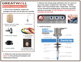
STEP 2: Remove the white plug from the fitting at the bottom of the
module by pushing in the small white collet and pulling out the plug
simultaneously. See “Using Push-in Fittings” on previous page
STEP 3: Remove the sanitary protective cap from the top of the module.
STEP 4: Connect the red SFC reject tubing by inserting it into the fitting
as far as it will go, located at the bottom of the RO membrane module.
Line up the module ears (See Fig 7), insert the module and push it into
the head until it is fully seated. Twist the module 1/4 turn to the right to
lock it into place. The final orientation should be such that the module
fitting is located towards the rear.
STEP 5: Install remaining replacement filters into their respective filter
heads using the icon coded labels, matching the replacement filters with
their corresponding filter heads (See Fig 9).
To mount the filtration assembly, elevate it at least 2” (5 cm) off
of the cabinet floor and, while keeping it level, mark the location of the
mounting holes on the cabinet side wall. Make small pilot holes with an
awl or a drill and screw in the two mounting screws; leaving just enough
protruding to allow the bracket mounting slots to slide over them.
NOTE: If the cabinet side walls are not of solid construction, the
filtration assembly can be set on the cabinet floor and held against the
side wall with the mounting screws. However, the filtration assembly
will then need to be lifted from the mounting screws in order to remove
the replacement filters.
The storage tank may be oriented either vertically or horizontally. It is
generally placed to the rear of the cabinet but can be set in the front
center (between the sink basins) for ease of access if space permits.
K. MAKE THE TUBING CONNECTIONS
With all of the components in place, the tubing connections can
be made. When routing the tubing between the components, several
guidelines should be observed.
• Tubing runs should generally follow the contour of the cabinet
rather than interfere with the cabinet storage area.
• Strive for a neat and orderly tubing “flow” by using fasteners (e.g.
insulated staples) to secure the tubing.
• Arrange the tubing so that there are no sharp bends. Leave some
“play” in the tubing for ease of servicing, then cut the tubing to the
desired length.
• Try to keep the tubing from the filtration assembly to the tank
and faucet as short as practical for good flow.
Undercounter Installation:
The filtration system will use 1/4” orange, 1/4” green, 3/8” blue,
3/8” black and 3/8” yellow tubing supplied with the system.
1) The 1/4” orange tubing should have already been connected to
the feedwater connection under Section G. Insert the other end into
the “Feed” connection labeled on the filtration system (right side).
2) Attach the 1/4” x 3/8” union to 1/4” blue tubing on faucet.
3) Insert one end of the 3/8” blue tubing into the “Faucet” connection
labeled on the filtration system (left side), and the other end into
the 1/4” x 3/8” union per Step 2.
4) Connect the 3/8” black tubing from the air gap faucet to the
drain saddle so that it slopes continuously downward without any
loops or low spots. Cut the tubing to the proper length and connect
it to the drain elbow.
5) Insert one end of the 3/8” yellow tubing into the “Tank”
connection labeled on the filtration system, and the other end into
the tank valve.
6) Route the special red SFC tubing with 1/4” union connector from
the RO membrane module to the 1/4” green tubing connected
to the faucet. Do not cut this special SFC tubing. It’s length is
important to maintain proper efficiency and performance.
L. START UP THE SYSTEM
1) Double check to see that all of the connections are secure.
2) Open the cold water feed valve and check the system for
leaks. If any leaks are detected, close the valve and correct the
problem before proceeding. NOTE: If a leak occurs at a “Push In”
plastic fitting, then refer to page 7, “Using Push-In Fittings”.
3) Lift the faucet handle and open the storage tank valve until a
steady stream of water flows. Close the faucet, wait at least five (5)
minutes and carefully check for leaks. Correct them as necessary.
M. FLUSH THE SYSTEM AND CHECK OPERATION
1) With the tank valve closed (the tank should still contain the
sanitizing solution at this point), open the faucet (set the faucet
handle in the “up” position) and feedwater valve. Water should
begin to drip from the faucet within several minutes. Continue
to flush the system for 24 hours. Water will steadily drip from
the faucet at the time. During this procedure, the tank is being
intentionally bypassed in order to thoroughly sanitize the tank and
also flush the membrane of any sanitizers.
2) After flushing for 24 hours, shut off the faucet. Open the tank valve,
lift the faucet handle again and allow the tank to completely empty.
When the water begins to drip steadily from the faucet the tank
should be empty.
3) Close the faucet and reinspect the system for leaks. Allow the tank
to fill completely (it will take approximately 4 hours), then drain the
tank again. The water should be discarded because it may contain
small amounts of sanitizer or sanitizing solution.
4) The system should be ready to use as soon as the tank refills.
If any objectionable taste is noticed after the second tankful is
drained, drain the tank the following day.
8

9
N. INSTALLATION TROUBLESHOOTING
Problem: Leak at the drain saddle.
Possible Cause: Drain saddle not clamped tightly enough.
Solution: Tighten the drain saddle screws evenly and firmly.
Problem: Leak at the fittings threaded connection.
Possible Cause: Fitting is improperly taped or not tightened sufficiently.
Solution: Retape the threaded portion with PTFE tape and thread it in
firmly. Do not over tighten.
Problem: Leak at the fittings push-in connection.
Possible Cause: Tubing is damaged if there is a tubing misassembly.
Solution: Remove the tubing. Squarely cut off 1/4 inch from the end
of the tubing using a sharp razor knife and reinsert it into the fitting.
Make sure that the tubing is pushed in completely until it seats. Refer to
“Using Push-In Fittings” Section on page 7.
Problem: Leak at the replacement filter head.
Possible Cause: Damaged or misaligned O-ring.
Solution: Close the cold water feed valve and the storage tank valve.
Lift up on the faucet handle and drain the system a minimum of five (5)
minutes. Remove the replacement filter where leak is found. Ensure
both o-rings are present on the replacement fi lter and are seated into
grooves; moisten o-rings with water. DO NOT use any petroleum
products to lubricate the o-rings.
Problem: The faucet leaks from the spout with the handle down.
Possible Cause: An obstructed or damaged valve seat in the faucet
mechanism.
Solution: Call Customer Care team at 1-877-238-9119 for assistance
in attempt to repair.
Problem: No steady drip from the open faucet after the tank is drained.
Possible Causes:
•
The cold water feed valve is not open.
•
A leak from any product water fitting connection.
•
Air is still trapped in the system.
Solutions:
•
Open the cold water feed valve completely.
•
Correct the fitting leak as outlined above.
•
Wait for the air to be purged from the system.
Problem: Water leaks from air gap module opening.
Possible Causes:
•
The drain line is blocked or the drain hole is not drilled through
completely.
•
The drain line has a loop in it.
•
Air is locked in the air gap outlet.
•
There is excessive RO reject flow.
Solutions:
•
Check to see that the drain line is clear of any obstruction and
remove the drain saddle fitting to verify that the hole is drilled
through completely.
•
Shorten tubing so that it is as vertical as possible.
•
Blow air into the air gap outlet using a short length of tubing.
•
Disconnect the red SFC reject tubing from the faucet air gap inlet
tubing and check the reject flow rate. It should be less than 5.9
ounces/min. If it is greater than 5.9 ounces/min., replace the red SFC
reject tubing with the new one of proper length.
Problem: Too little or no reject flow.
Possible Causes:
•
Red SFC reject tubing is plugged or damaged.
•
The cold water feed valve is not open.
Solutions:
•
Replace the SFC reject tubing with one of proper length.
•
Open the cold water feed valve completely.
Problem: Chlorine or other unpleasant taste/odor is evident after the
initial tank filling.
Possible Cause: Residual sanitizer is still in the water.
Solution: Drain and fill the storage tank several times if necessary.
Problem: Noise in the drain (gurgling or dribbling sound).
Possible Cause: The reject water is dripping into the standing water in the
drain trap.
Solutions:
•
Make sure that the 3/8” black drain tubing from the faucet air gap
module slopes continuously downward to the drain saddle without
any loops or low spots.
•
Angle the drain piping so that the reject water runs down the side
of the drain pipe.
•
Change the location of the drain saddle to the horizontal drain
pipe or any alternate vertical drain pipe which is farther from the
trap. Properly plug the original hole. Caution: Make sure the drain
saddle is always installed above (before) the trap.
•
Drill larger hole in drain pipe.
Problem: Little or no water available.
Possible Cause:
•
Tank has not had time to fill.
•
Tank has little or no air charge.
• RO membrane module output significantly below normal.
Solutions:
•
Wait. The tank will take approximately 4 hours to fill.
•
An empty tank with the ball valve open to atmosphere, should have
a 7-8 psi air charge.
•
Contact 3M Clean Water Solutions Customer Care Team at 1-877-
238-9119 for instructions.

A. IMPORTANT WATER QUALITY ASSURANCE
REQUIREMENTS
Reverse Osmosis drinking water filtration systems contain
treatment components that are critical for the effective reduction of
Total Dissolved Solids (TDS) as well as some inorganic chemical
contaminants. It is strongly recommended that the user test the water
periodically (every six (6) months minimum) to verify that the system is
performing satisfactorily. Routine maintenance is necessary in the form
of sediment, granulated carbon filter and membrane module, based on
the following guidelines:
• Sediment Replacement Filters, Granulated Carbon Replacement
Filters & Carbon Block Replacement Post-Filters: Change every
twelve (12) months, at the rated capacity or sooner if a noticeable
reduction in flow rate occurs.
• RO Membrane Replacement Module: Change it as required based
on 90 Percent Rejection. The recommended maximum service
life is thirty-six (36) months, at the rated capacity or sooner if a
noticeable reduction in flow rate occurs.
How Much Water Should the Tank Hold?
The amount of water the storage tank will hold is determined by the
air precharge and the feed water pressure. The RO system will fill the
tank until the pressure in the tank reaches two-thirds of the feed water
pressure. With an air precharge of 7-8 psi (48-55 kPa), the following
chart lists approximate storage capacities when the tank is full:
Feed Water Pressure Tank Capacity
80 psi (552 kPa) 2.2 gallons (8.3 liters)
60 psi (414 kPa) 2.1 gallons (7.9 liters)
40 psi (276 kPa) 1.5 gallons (5.7 liters)
B. REPLACING THE FILTERS
NOTE: It is essential that the filters be installed in the correct
location. Use the icon coded labels to match the filter cartridges with
their corresponding filter head.
The life of the filters generally depends on the local water conditions
(i.e., sediment, rust and/or chlorine levels) while the life of the post-filter
is generally determined by the length of service.
When to Replace the Sediment Replacement Filter
• Every twelve (12) months
or sooner depending on local water conditions.
• A noticeable decrease in water production is an indication that the
filter requires changing.
When to Replace the Granulated Carbon Replacement Filter
The granulated carbon replacement filter reduces free chlorine in
the feed water supply to protect the TFCM membrane from chlorine
attack. To find out the chlorine level in a water supply, call the public
water supplier.
When to Replace the Carbon Block Replacement Post-Filter
• If the filter is being used to control tastes and odors, replace it every
twelve (12) months or sooner depending on local water conditions.
How to Replace the Filters
1) Lift up on the faucet handle and close the cold water feed valve.
Wait five (5) minutes for the filtration assembly to completely
depressurize.
2) Remove cover.
3) Twist the existing filter 1/4 turn to the left so that the ears on the
filter are able to disengage from the head. Firmly pull the filter from
the head. It may be necessary to twist the filter slightly from side
to side to help free it.
4) Remove the new replacement filter from its protective wrap.
(Double check to see that it is the correct replacement by
comparing the labels.)
5) Remove the protective sanitary cap from atop the replacement filter.
6) Ensure both o-rings are present on the replacement fi lter and are
seated into grooves; moisten o-rings with water. DO NOT use any
petroleum products to lubricate the o-rings.
7) Line up the filter ears, insert the filter and push it into the head until it
is fully seated. Twist the filter 1/4 turn to the right to lock it into place.
(See Fig 7)
8) Open the cold water feed valve, and carefully check for leaks.
9) RO System Flush Instructions
Sediment & Granulated Carbon Replacement Filters — Close tank.
Lift the faucet handle and flush at least two (2) gallons of water
through system (approximately 10 minutes).
Carbon Block Post-Filter — Open tank. Lift the faucet handle
and flush at least two (2) gallons of water through post-filter
(approximately 30 minutes with tank empty or 5 minutes with
tank full). It may be necessary to continue flushing until water
becomes clear.
C. REPLACING THE RO MEMBRANE MODULE
The life of the RO membrane module depends on the local water
conditions and proper maintenance, e.g., regular module changes.
Under typical conditions, the RO membrane module life is thirty-six (36)
months or sooner. Unlike the replacement filters, the RO membrane
module life is not determined by the amount of water used because of
its self-cleaning feature.
How to Replace the RO Membrane Module
1) Lift up on the faucet handle and close the cold water feed valve.
Wait five (5) minutes for the filtration assembly to completely
depressurize.
2) Remove cover.
3) Make sure that there is some slack in the red SFC tubing
connected to the fitting at the bottom of the RO membrane
module. Twist the module 1/4 turn to the left (counterclockwise)
so that the tubing connection is accessible. (See Fig 7)
4) Remove existing red SFC tubing from faucet adapter and membrane
module by depressing the small collet and pulling the tubing away
from the fittings.
II. Operation & Maintenance Instructions
10
Failure to install, operate or maintain your fi lter system in accordance with these use instructions or
any other installation or use instructions accompanying this product may result in product failure and
property damage, including water leakage and will void warranty.
• Replacement of fi lters will result in the need to sanitize the fi ltration
system and/or the storage tank. Please refer to Section D “Sanitizing
the RO System” on page 11 for further instructions.
IMPORTANT NOTES

5) Firmly pull the module away from the head. (It may be
necessary to twist the module slightly from side to side.)
6) Remove the new RO membrane module from its protective
wrap. (Double check to see that it is the correct replacement by
comparing the labels.)
7) Remove the sanitary plastic cap atop the module.
8) Ensure both o-rings are present on the replacement fi lter and are
seated into grooves; moisten o-rings with water. DO NOT use any
petroleum products to lubricate the o-rings.
9) Connect the new red SFC reject tubing (supplied with replacement
membrane module) by inserting it into the fitting at the bottom of
the new RO membrane module as far as it will go, and into the
faucet adapter. Line up the module ears, insert the module and
push it into the head until it is fully seated. Twist the module 1/4
turn to the right (clockwise) to lock it into place.
10) Open the cold water feed valve, and carefully check for leaks. Carefully
inspect the fitting at the bottom of the new RO membrane module.
11) For sanitization of RO system please follow instructions below in
Section D.
12) Flush membrane module - refer to Section M, Step 1 and 2 on
page 8.
D. SANITIZING THE RO SYSTEM
Follow the sanitizing procedure for the storage tank and the filtration
assembly outlined below, followed by 24 hour flush with tank empty
and faucet open.
To help provide you with the highest quality water from your RO
Drinking Water Filtration System, it is important to routinely sanitize
both the storage tank and the filtration assembly as noted below.
IMPORTANT NOTE: These procedures are only intended to be part of
a routine maintenance program only and are not designed to sanitize
systems that have become highly contaminated from misuse.
When to Sanitize the Storage Tank
• Upon start-up as described in the beginning of this manual.
• After any servicing or routine maintenance which involves the RO
membrane module, carbon block post-filter, storage tank or faucet.
When to Sanitize the Filtration System
• After any servicing or routine maintenance which involves the
sediment and granulated carbon replacement filters or the RO
membrane replacement module.
How to Sanitize the Storage Tank and Filtration System
Sanitizing the storage tank generally requires:
•
Common household bleach (5.25% non-scented)
•
Eye dropper or plastic oral syringe
1) Close the cold water feed valve and lift up on the faucet handle to
empty the water in the storage tank. It should feel light when
empty.
2) Disconnect the 3/8” yellow tubing (system tank) from the ball
valve on top of the storage tank.
3) Insert into the yellow tubing 1/2 teaspoon (3 ml) of household
bleach. (See Fig 8)
4) Reconnect the yellow tube to the tank ball valve.
5) Close the RO faucet and open the cold water feed valve.
6) Wait 4-5 hours.
7) Life up the handle of the RO faucet and allow contents of tank to
drain completely into the sink.
8) Sanitizing is now complete.
9) If there is any residual chlorine/bleach taste in the next tank full,
drain tank completely a second time.
E. LONG TERM NON-USE
If the RO system is to be left unused for a long period of time
(greater than 30 days), install new replacement filters.
11
Remove the red SFC tubing from
the fitting before completely
removing the RO membrane modul
e
O
N
O
F
F
Fig. 7
WARNING
To reduce the risk associated with ingestion of water contaminated
with sanitizer:
• After installation, sanitizers must be fl ushed from the system
before fi rst use as directed within the installation instructions.

Fig. 8
Fig. 9
1/2 Tsp.
5.25%
Unscented
Bleach
Eyedropper
with Bleach
Storage Tank
Carbon Block (post)
Membrane
Granulated Carbon
Sediment
III. Limited Warranty
Limited Warranty: 3M Purifi cation Inc. warrants this Product will be free from
defects in material and manufacture for the following periods from the date
of purchase: Five (5) years for the Product, except for the replacement fi lter
cartridge and membrane, which are warranted for one (1) year. This warranty
does not cover failures resulting from abuse, misuse, alteration or damage not
caused by 3M or failure to follow installation and use instructions. No warranty
is given as to the service life of any fi lter cartridge or membrane as it will vary
with local water conditions and water consumption. If the Product fails to
satisfy this Limited Warranty during the warranty period, 3M will replace the
Product or refund your Product purchase price. This warranty does not cover
labor. The remedy stated in this paragraph is Customer’s sole remedy and 3M’s
exclusive obligation.
This warranty gives you specifi c legal rights, and you may have other rights
which may vary from state to state, or country to country. For any warranty
questions, please call 1-877-238-9119 or mail your request to: Warranty
Claims, 3M Purifi cation Inc., 400 Research Parkway, Meriden, CT 06450. Proof
of purchase (original sales receipt) must accompany the warranty claim, along
with a complete description of the Product, model number and alleged defect.
Limitation of Liability: 3M will not be liable for any loss or damage arising
from this 3M product, whether direct, indirect, special, incidental, or conse-
quential, regardless of the legal theory asserted, including warranty, contract,
negligence or strict liability. Some states and countries do not allow the
exclusion of limitation of incidental or consequential damages, so the above
limitation or exclusion may not apply to you.
3M is a trademark of 3M Company.
© 2010 3M Company. All rights reserved.
INSTR8031 0810
Manufactured by 3M
400 Research Parkway
Meriden, CT 06450
1-877-238-9119
www.3MCleanerWorld.com
/