3M
™
Filtration Products
3M
™
High Flow Sanitary Design Filter Housings (40” and 60”)
Installation and Operating Instructions

2
Failure to follow installation, operation, and maintenance instructions may result in unit failure and will void warranty.
Intended Use
These 3M High Flow Sanitary Design Filter Housings have been evaluated for use in the filtration of food & beverage
and process fluids and have not been evaluated for use in any other applications. It is the end user’s responsibility
to ensure process fluids are compatible with the materials of construction and can be safely used. The products are
intended for installation by qualified installers in accordance with these installation instructions, local regulations/
codes, and industry requirements.
Safety Information
Please read, understand, and follow all safety information contained in these instructions prior to the use of these
3M
TM
High Flow Sanitary Design Filter Housings. Retain these instructions for future reference.
WARNING
To reduce the risks associated with explosion, burns, or exposure to contaminants:
• Always shut off inlet effluent supply and depressurize system as shown in manual prior to service.
To reduce the risks associated with fire or explosion:
• Removal of packaging used with this product may produce static electrical charges or sparks, risking combustion of
flammable or explosive materials, liquids, or gases. Only open packaging in an area free of flammable and explosive
materials.
To reduce the risks associated with explosion and exposure to contaminants:
• Always operate the housing within the pressure and temperature design limits. Refer to the housing nameplate for this
information.
• Do not modify the vessel or its components.
• Over-pressurization of liquid should be prevented by the installation of proper pressure relief valves.
• Never, for whatever reason, open the filter housing’s closure nuts and bolts during operation or under pressure
regardless of how low the pressure is.
• Use only 3M replacement parts.
• Replacement parts must be installed by personnel trained and equipped to service filter vessels.
• Ensure system is maintained above the freezing temperature of the process fluid.
• Do not use a vessel that has been damaged or has damaged components.
To reduce the risks associated with impact and exposure to contaminants:
• Ensure product does not experience any external loads or forces on the vessel.
• These systems have not been evaluated for seismic activity.
To reduce the risks associated with explosion:
• Use filter for liquid service only. Not for continuous gas service.
To reduce the risks associated with impact:
• Do not open or remove filter housing cover unless the filter housing is bolted and anchored in place
To reduce the risks associated with exposure to contaminants:
• Ensure that all system pressure has been relieved and inlet/outlet valves are closed prior to opening the system to
atmosphere.
• Avoid water hammer.
• Always use appropriate personal protective equipment (PPE) when installing or servicing the filter housing, or when
changing filter elements.
• This product must be installed per the appropriate federal, state, or local plumbing and pressure standards to ensure
safe use in the desired application.
• Dispose of used filter housing or cartridge in accordance with federal, state, and local laws and regulations.
EXPLANATION OF SIGNAL WORD CONSEQUENCES
WARNING
Indicates a potentially hazardous situation, which, if not avoided, could result in
serious injury or death.
CAUTION:
Indicates a hazardous situation which, if not avoided, could result in minor or moder-
ate injury and/or property damage.
NOTICE
Indicates a situation which, if not avoided, could result in product or system damage.

3
These instructions include:
1. Assembling the housing saddle
(stand) or legs (single lter
models only);
2. Installing Vent Valves, Inlet/
Outlet Drain Valves and Pressure
Gauges;
3. Cover Closure and operation for
swing bolt.
II. 3M™ High Flow Sanitary Design Filter
Housing Installation.
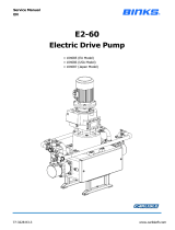
NOTE: 3M High Flow Sanitary Design
Filter Housings are available in horizontal
models (see Figure 1). When installing,
ensure that the drains are downward
facing to allow proper housing drainage.
Check to ensure that there is adequate
Inspect all sealing surfaces (including cover o-ring groove,
flanges, and threaded connections) to ensure that they are
free of damage (scratches etc.) that may prevent proper
sealing.
If the housing is to be installed into a new system, plumb the
system to the dimensions noted on the proposal drawing (or
the final assembly drawing).
NOTE: Housing is supplied with flange covers and thread
protectors for vents, drains and gauge ports. These must be
removed and replaced with the proper plugs, system piping,
or gauges.
Table 1. - 3M™ High Flow Sanitary Design Filter Housings Details
Figure 1. - 3M™ High Flow Sanitary Design Filter Housing
To reduce the risk associated with tipping over of the
housing due to the housing not being adequately fastened
down:
• Do not open or remove vessel cover unless vessel housing is
bolted and anchored in place.
WARNING
I. Introduction
The following instructions are for the
installation of all 3M High Flow Sanitary
Design filter housing models. 3M High Flow
series filter element installation/operating
instructions are packaged with each box of
filter elements.
NOTE: Always operate the housing within
the pressure and temperature design
limits. Refer to the housing nameplate for
this information. Do not exceed cartridge
operating parameters.
NOTE: Housing should be rinsed and
cleaned prior to use.
Part Number Description
1HFX40HCS
1-Around 40” High Flow, Non-Code, Horizontal,
316L SS, EPDM Gasket, 3" Sanitary Inlet/Outlet
1HFX60HCS
1-Around 60” High Flow, Non-Code, Horizontal,
316L SS, EPDM Gasket, 3" Sanitary Inlet/Outlet
space around the housing to allow for easy removal of the
lter element and that there is enough clearance to swing the
cover to the fully open position. Install valves in the process
lines coming into and going out of the housing to stop the uid
ow through the lter during element change-outs.
Unpack and inspect the lter housing. Check to ensure that all
parts are supplied and in serviceable condition.
Cover
CAUTION
NOTICE – To Reduce Product Damage:
To reduce the risks associated with pinch hazards:
• Do not place hands or fingers under the vessel cover where they can be pinched.
• Ensure differential pressure is not exceeded prior to filter cartridge replacement.

4
II. 3M™ High Flow Sanitary Design Filter Housing
Installation.
1. Unpack the saddle stand. Check to ensure
that all parts are supplied and in serviceable
condition. Parts included are (Table 2):
2. Using two 3/8” Hex Head bolts, two 3/8” lock
washers, and two 3/8” diameter washers, attach
the Saddle Reinforcement to the Outlet Side
Saddle. Repeat for the Cover Side Saddle.
3. Place the saddle in the installation location.
Ensure that Outlet Side Saddle aligns with the
outlet (downstream) pipe. Using an appropriate
hoist or other lifting device, place the housing
onto the saddle. Remove the inlet/outlet
flange covers and all other thread protectors
(drains, vents, gauge ports etc). Make
sure the housing drains and inlet flange are
facing downward (see Figure 2) and the
front saddle is between the inlet and drain.
4. Locate the four U Bolt mounting holes in saddle.
Position a 5/8” diameter washer over each hole.
5. Install a 5/8”-11 Hex Nut on each threaded end
of the U Bolt.
6. Place the two U Bolts over the housing and
through the washer/saddle hole.
7. Install 5/8” diameter washer and 5/8”-11 Hex
Nut on each threaded end of the U Bolt
and tighten until housing is secure.
8. Ensure correct alignment with the system
connections (flanges).
9. Using the 1 inch holes in the saddle base as a
template, anchor the housing to the floor using
appropriate fasteners. Ensure compliance with
all local, state and federal codes.
10. Connect the system (up- and downstream)
pipes to the housing. Ground the housing, in
accordance with local code. Tighten the
housing floor/pad mounting bolts, as required.
Figure 2. - Model 1HF Horizontal Housing Saddle Assembly Details
Table 2. - Saddle Stand Components
INSTALLATION NOTE: The saddle is designed to provide the correct housing angle (2 to 3 degree slope
downward from cover to outlet) to ensure proper housing drainage. Ensure that the platform or floor where the
housing is to be located is level.
Description
Component ID
(see Figure 2)
Quantity
1
5
9
Leg Weldment - Higher
Screw - Hex Head
(M12 X 50 mm LG)
1
4
2 Leg Weldment - Lower 1
3
7
Leg Weldment - Center Lift 1
4
8
6
Plate - Housing Clamp
Washer - Plain (M12)
Washer - Spring (M12)
Nut - Hex (M12)
Screw - Hex Head
(M12 X 30 MM LG
2
12
12
12
8
1
2
3
4
5
6
7
8
9

5
Cartridge Installation Instructions:
1. Ensure that lter o-ring is properly seated in
the o-ring groove of the bottom end-cap. This
o-ring is not reusable. Verify compatibility with
the chemistry and temperature of the process
uids. O-rings are available in a variety of
materials designed to be compatible with most
manufacturing processes.
2. Insert the lter cartridge on the center post.
Push the cartridge into the housing until it is
fully seated. To ensure proper cartridge seating,
gently twist the handle back and forth while
pushing the cartridge into the housing.
3. Slowly turn the cartridge clockwise holding the
handle rmly until it stops (after 90° rotation).
At this point, the o-ring is fully engaged into the
receptacle. Maximum allowable turning torque:
100 inch-pound. To ensure that the cartridge is
locked into the housing cartridge receptacle,
gently pull the cartridge as if removing it. If the
cartridge releases, repeat steps 2 and 3.
4. Close the lter housing cover (see Cover
Closure).
Figure 5. - Cartridge Installation
To reduce the risk associated with pinched ngers
due to ngers being placed under the lter cover:
• Do not place hands or ngers under the vessel
cover where they can be pinched.
CAUTION
Cartridge Removal Instructions
Normally the lter life endpoint is determined by the
pressure dierence across the lter cartridge. The
terminal pressure drop is dependent on the application,
but should not exceed 35 psid.
1. Close inlet and outlet valves. Open the vent
valve to relieve system pressure.
2. Open the drain valve and allow the vessel
to drain completely.
3. Loosen the mounting bolts on the cover and
swing the bolt away from the housing. Swing
the cover to the open position.
4. Turn the lter cartridge handle 90° (Figure 6)
counter- clockwise until it releases out of the
bottom receptacle.
5. Pull the cartridge handle to remove the lter.
6. Install new lters (see Cartridge Installation
Instructions).
Figure 6. - Cartridge Removal
To reduce the risk associated with exposure to
contaminants:
• Dispose of used lter cartridge in accordance
with federal,state, and local laws and regulations.
WARNING
To reduce the risk associated with pinched ngers
due to ngers being placed under the lter cover:
• Do not place hands or ngers under the vessel
cover where they can be pinched.
CAUTION

6
Product Selection and Use:
Many factors beyond 3M’s control and uniquely within user’s knowledge and control can aect the use and
performance of a 3M product in a particular application. As a result, customer is solely responsible for evaluating
the product and determining whether it is appropriate and suitable for customer’s application, including
conducting a workplace hazard assessment and reviewing all applicable regulations and standards (e.g., OSHA,
ANSI, etc.). Failure to properly evaluate, select, and use a 3M product and appropriate safety products, or to meet
all applicable safety regulations, may result in injury, sickness, death, and/or harm to property.
Warranty, Limited Remedy, and Disclaimer:
Unless a dierent warranty is specically stated on the applicable 3M product packaging or product literature
(in which case such warranty governs), 3M warrants that each 3M product meets the applicable 3M product
specication at the time 3M ships the product. 3M MAKES NO OTHER WARRANTIES OR CONDITIONS,
EXPRESS OR IMPLIED, INCLUDING, BUT NOT LIMITED TO, ANY IMPLIED WARRANTY OR CONDITION OF
MERCHANTABILITY, FITNESS FOR A PARTICULAR PURPOSE, OR ARISING OUT OF A COURSE OF DEALING,
CUSTOM, OR USAGE OF TRADE. If a 3M product does not conform to this warranty, then the sole and exclusive
remedy is, at 3M’s option, replacement of the 3M product or refund of the purchase price.
Limitation of Liability:
Except for the limited remedy stated above, and except to the extent prohibited by law, 3M will not be liable
for any loss or damage arising from or related to the 3M product, whether direct, indirect, special, incidental,
or consequential (including, but not limited to, lost prots or business opportunity), regardless of the legal or
equitable theory asserted, including, but not limited to, warranty, contract, negligence, or strict liability.
Cover Closure
Prior to closing the housing cover, ensure that the o-ring is properly placed in the groove on the housing.
1. Swing the housing cover closed.
2. Swing the eye bolt assemblies up and into the
cover slots.
3. Hand tighten each eye nut.
4. Using a screwdriver or bar, tighten each eye nut by 1/2 turn until metal-to-metal contact
between the cover and the housing is achieved.
Filling
1. Ensure that the vent on the top of the housing is open. Close all drains.
2. Slowly open the process inlet valve to introduce uid to the housing. Completely ll the housing
with process uid until this uid begins to exit the vent.
3. Close the vent valve.
4. Slowly open the inlet valve to its “full open” position.
5. Slowly open the outlet valve to its “full open” position.
The 3M High Flow Sanitary Design Filter Housing Models 1HFX40HCS and 1HFX60HCS use standard size O-Rings
(Parker 2-452). End-users are responsible for evaluating whether replacement O-Rings meet all the chemical
compatibility and regulatory requirements of their application.

7
Notes

3M is a trademark of 3M Company.
Please recycle. Printed in U.S.A.
© 2018 3M Company. All rights reserved.
34-8723-2989-0
3M Purification Inc.
Separation and Purification
Sciences Division
400 Research Parkway
Meriden, CT 06450 U.S.A.
(800) 243-6894
(203) 237-5541
www.3Mpurication.com
/