aqua-pure AP-RO5500 User manual

Category
Sanitary ware
Type
User manual
Installation, Operation and Maintenance Instructions For:
Aqua-Pure
®
AP-RO5500 Reverse Osmosis
Drinking Water Filtration System
Installer: Please leave manual with homeowner.
Homeowner: Please retain for operation and future
maintenance instructions.
98-880043 0609
SAFETY INFORMATION
EXPLANATION OF SIGNAL WORD CONSEQUENCES
WARNING
Read, understand, and follow all safety information contained in these instructions prior to in-
stallation and use of the AP-RO5500 Reverse Osmosis (RO) Drinking Water Filtration System.
Retain these instructions for future reference.
Intended use:
The Aqua-Pure
®
AP-RO5500 Reverse Osmosis Drinking Water Filtration System is intended for use in filtering
drinking water in residential locations and has not been evaluated for other uses. The system is typically installed
beneath or near a kitchen sink, and it is recommended that the installation be performed by a qualified installation
specialist or a licensed plumber.
CAUTION
WARNING
Indicates a potentially hazardous situation, which, if not avoided, could result in
death or serious injury and/or property damage.
Indicates a potentially hazardous situation, which, if not avoided, may result in
property damage.
To reduce the risk associated with choking:
•Do not allow children under 3 years of age to have access to small parts during the installation of this product.
To reduce the risk associated with eye, skin and respiratory and digestive tract burns from Calcium
Hypochlorite during installation:
•CalciumHypochlorite(CAS7778-54-3)granulesareusedfortanksanitationinthisproduct.
•Duringinstallation,donotgetineyesoronskinorclothing.Donotingest.Weareyeandfaceprotection.
Keep out of reach of children.
•Forfurthersafetyinformation,refertoMSDSdocumentsavailableatCHEMTREC(1-800-262-8200)or
www.3M.com.
To reduce the risk associated with ingestion of water contaminated with Calcium Hypochlorite sanitizer:
•Afterinstallation,sanitizermust be flushed from the system before first use as directed within the installation
instructions.
To reduce the risk associated with ingestion of contaminants:
•Do not use with water that is microbiologically unsafe or of unknown quality without adequate disinfection be-
fore or after the system.
To reduce the risk associated with a hazardous voltage due to an installer drilling through existing elec-
tric wiring or water pipes in the area of installation:
•Do not install near electric wiring or piping which may be in the path of a drilling tool when selecting the
position to mount the filter bracket.
1
Installation, Operation and Maintenance Manual
CAUTION
IMPORTANT NOTES
To reduce the risk associated with property damage due to water leakage:
• Read and follow Use Instructions before installation and use of this system.
• InstallationandUseMUST comply with all state and local plumbing codes.
• Protect from freezing.Drainlterwhentemperaturesdropbelow40°F(4.4°C).
• Do notinstallifwaterpressureexceeds125psi(862kPa).Ifyourwaterpressureexceeds125psi,you
mustinstallapressurelimitingvalve.Contactaplumbingprofessionalifyouareuncertainhowtocheck
your water pressure.
• Do not install where water hammer conditions may occur. If water hammer conditions exist you must install a
waterhammerarrester.Contactaplumbingprofessionalifyouareuncertainhowtocheckforthiscondition.
• Thesystemmust be installed on COLDwaterlinesonly,maximumtemperatureis100°F(37.8°C).
•Thesystemmustbeinstalledwiththeinletandoutletportsaslabeled.Makesurenottoreverseconnections.
Thedisposableltercartridgemust be replaced every six months or at the specified service cycle.
• Do not use a torch or other high temperature sources near filter or plastic fittings.
• Do not install in direct sunlight.
• Do not install near water pipes which will be in path of a drilling tool when selecting the position to mount
the bracket.
• Mountlterinsuchapositionastopreventitfrombeingstruckbyotheritemsusedintheareaofinstallation
(wastebaskets,etc).
• Onplasticttings,neverusepipesealantorpipedope.Usethreadsealingtapeonly.
• Ensure all tubing and fittings are secure and free of leaks.
• Do notinstallunitifcolletismissing.ContactCUNOifcolletsaremissingfromanyttings.
•SHUT OFF FUEL SUPPLY TO WATER HEATER after water is shut off.
• Shutoffinletwatersupplyanddepressurizesystemasshowninmanualwhenchangingcartridgesorservicing.
•Failuretofollowinstructionsmayvoidwarranty.
•Allowaminimumof71/2”(19.5cm)clearspaceunderltertofacilitatecartridgechange.
• Donotcrimpcoppertubing.
Somestateandlocalplumbingcodesmayprohibittheuseofsaddle-typevalvesand/ordrainconnections.
Theuseofsaddle-typevalvesareprohibitedin:Alaska,Delaware,Idaho,Kentucky,Massachusetts,Michi-
gan,Minnesota,NewHampshire,NorthDakota,Ohio,OreganandSouthDakota.Checkyourlocalplumb-
ing codes for any restrictions that apply.
•Itismandatorythatsafetyglassesbewornduringsinkholedrillingoperationstopreventeyeinjury.
2 3
Introduction
This manual explains installation and operation of the Aqua-Pure
®
AP-RO5500ReverseOsmosis(RO) Drinking
Water Filtration System. Please read each section of this manual carefully.
The Aqua-Pure AP-RO5500 RO Drinking Water Filtration System is designed to connect permanently to a home
plumbing system. To ensure that the installation conforms to your state and local plumbing codes, it is recommended
that the installation be performed by a qualified installation specialist for RO drinking water filtration systems or a
licensed plumber.
The RO module is shipped with a preservative solution. Make sure that you flush the system thorough-
ly as directed before the first use.
NOTE:MakesurethattheOwnersWarrantyRecordCardislledoutandmailedwithin10daysofinstallation.
Installation Checklist and Table of Contents
1. DetermineSystemLocation ..................................................................................................................... 4
2. PreparetheAreaforInstallation ............................................................................................................... 4
3. Prepare the Filtration System for Installation ............................................................................................ 4
4. InstalltheFeedWaterValveandTubing ................................................................................................... 5
5. Prefill and Sanitize the Storage Tank ........................................................................................................ 5
6. InstalltheDrainConnection...................................................................................................................... 6
7. InstalltheFaucet ...................................................................................................................................... 6
8. MaketheFaucetMountingHole ............................................................................................................... 7
9. MounttheFaucet ...................................................................................................................................... 8
10. MakeInitialFaucetTubingConnections ................................................................................................... 8
11. InstallthePuricationAssemblyandStorageTank .................................................................................. 9
12. MakeFinalTubingConnections ................................................................................................................ 9
13. InstallIcemakerHookup(optional) ......................................................................................................... 10
14. InstallFilterCartridges ........................................................................................................................... 10
15. StartUptheSystem ............................................................................................................................... 10
16. InstallationTroubleshooting .................................................................................................................... 11
17. Maintenance ........................................................................................................................................... 12
18. PartsList ................................................................................................................................................. 14
19. InstallationDiagrams(Figures1-6) ......................................................................................................... 15
20. LimitedOneYearWarranty ..................................................................................................................... 18
• Failuretofollowinstructionsmayvoidwarranty.
IMPORTANT NOTES
Installation, Operation and Maintenance Manual
4
1. Determine System Location (see Figures 1 and 2)
The Drinking Water Filtration System can be located under a sink or in a basement depending on space avail-
ability and preference. If a basement installation is selected, additional tubing, hardware and fittings may be
needed and a hole will have to be made from inside the cabinet, through the floor, to the basement.
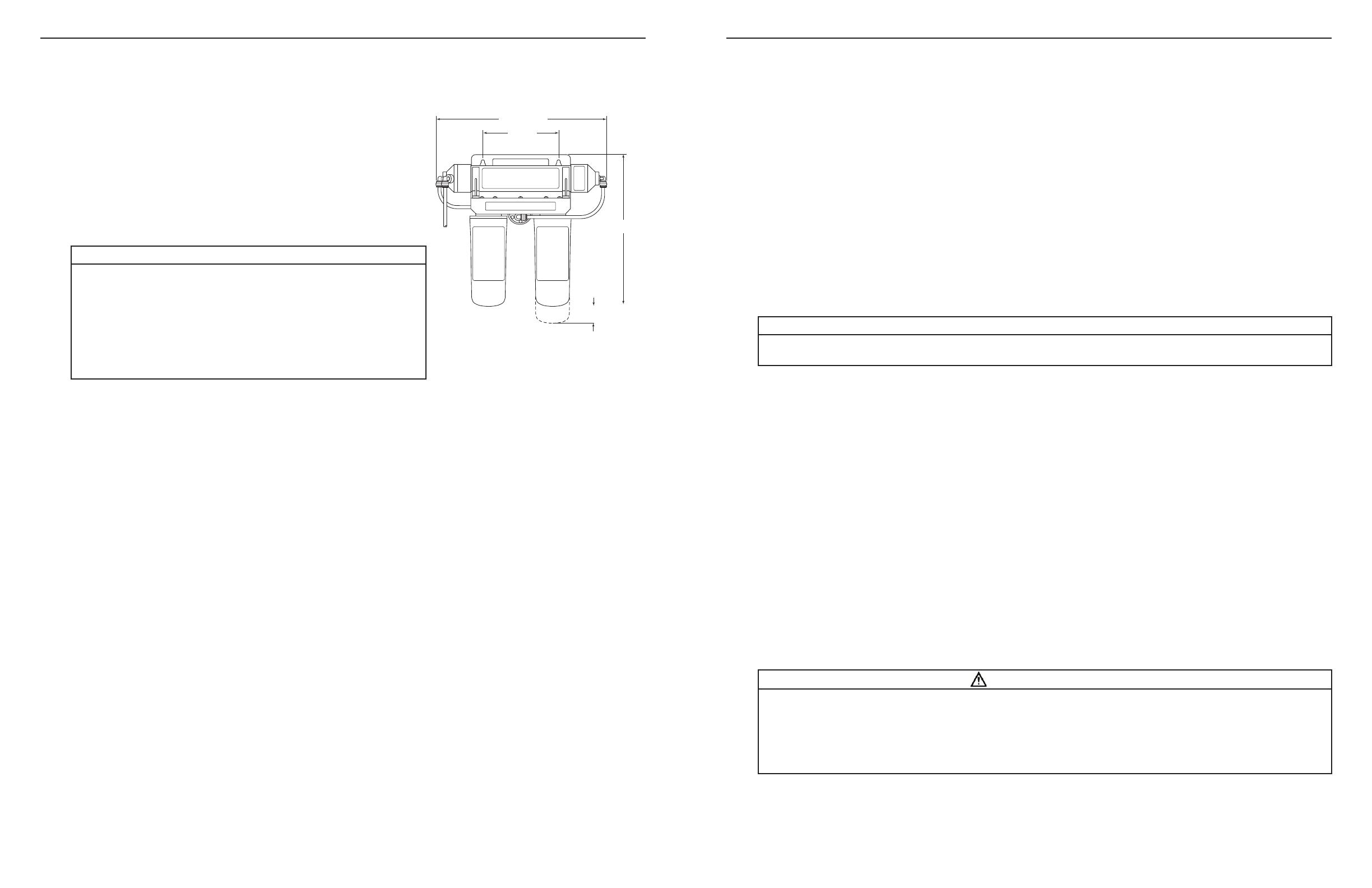
Space Requirements
NOTE:Neverinstalltheltrationsysteminanareaofthehome
where the temperature may drop to freezing as damage to the
system will result.
The exact placement of the various components of the filtration
system will vary from installation to installation. The installer must
decide on where to place the faucet, tank and purification assembly
by balancing convenience with ease of installation and servicing.
Considerationsforanicemakerorotherremotehookupshouldbepredetermined,includingplumbingrout-
ing and any additional tools, fittings and tubing that may be required.
Feedwater Conditions Parameter
pH 4-11
Manganese <0.05ppm(mg/L)
Hardness <350ppm(mg/L)
HydrogenSulde Noneallowable
Iron(FE) <0.3ppm(mg/L)
Organics <1ppm(mg/L)
FreeChlorine Upto3ppm(mg/L)
Temperature 40-100°F(4-38°C)
Turbidity <1NTU
TDS Upto2,000ppm
Min./Max.Feedwaterpressure40-100psi(276-690kPa)
2. Prepare the Area for Installation
Determine where components will be located and how they will be mounted. Special mounting brackets
and hardware may be necessary to secure the system to a wall or ceiling joists if a basement installation is
called for. Inspect the cold water supply line and drain to determine if any additional fittings are required.
NOTE:Itisagoodideaatthistimetochecktheconditionoftheundercounterplumbingforanyexistingor
potential leaks.
3. Prepare the Drinking Water Filtration System for Installation
Opentheshippingcartonandremovecomponents.Checkthatalloftheinstallationpartsarepresentwhich
includethereverseosmosis(RO)assembly,storagetank,faucet,installationhardware,andtubinglocated
in box under storage tank.
If an optional percent rejection monitor is used, the probes should be installed at this time. Follow the in-
structions that come with the monitor.
14 5/8" NOM
6 1/2"
14 1/8" NOM
1 1/2"
Minimum Distance
Required To Remove
Cartridges
To reduce the risk associated with property damage due to
water leakage:
• Protect from freezing. Drain filter when temperatures drop below
40°F(4.4°C).
• Do notinstallifwaterpressureexceeds125psi(862kPa).If
yourwaterpressureexceeds125psi,youmust install a pres-
surelimitingvalve.Contactaplumbingprofessionalifyouare
uncertain how to check your water pressure.
CAUTION
5
4. Install the Feed Water Valve and Tubing (see Figure 3)
Thefeedwatersaddlevalveisdesignedforusewith3/8”to1/2”ODsoftcoppertubing(plainorchromed)and
rigid metal pipe. Do not use with flexible ribbed supply tubing or plastic pipe which require special hardware.
Soft Copper Tubing Installations:
A) Turnoffcoldwatervalveunderthesink,orthemainwatersupplyvalveforthehouse.
B) Beforeinstallingfeedwatersaddlevalve,makesurepiercinglancedoesnotprotrudebeyondrubber
gasket. See instructions on bag.
C) Assemblebothhalvesoffeedwatersaddlevalveoncoppertubing.
D) For3/8”O.D.tubing,usebracketwithsideprojectionstopreventdistortionoftubing.UseV”sideofbracketfor
all larger size tubing. Tighten screws evenly and firmly — brackets should be parallel. Do not deform tubing.
E) Topiercesoftcoppertube,turnhandletotherightuntilitisrmlyseated.Thevalveisclosedinthisposition.
F) Turnonmainsupplyvalvetopressurizecoldwaterline.Checkforleaks.Ifvalvestemleaks,tighten
nut/seal with a wrench.
G)Connectlengthoforange1/4”tubingtofeedwatervalve,usingbrasscompressionnut,insertandplas-
ticsleeve(refertoFigure3).
Rigid Metal Pipe Installations:
A) Turnoffcoldwatersupplyvalveanddrainthelinetopreventspillage.
B) Drill3/16”holeatthedesiredlocation.Topreventshockhazard,useabatteryoperateddrill.
C) Turnvalvehandletotherighttoexposepiercinglancebeyondtherubbergasketnomorethan3/16”.
D) Assemblesaddlevalveonthesupplypipebyscrewingthetwohalvestogether.Usethe“V”sideofthe
bracket. Tighten screws evenly and firmly, keeping the two sides of the bracket parallel.
E) Turnsaddlevalvehandletotherighttoclosevalve.Ifvalvestemleaks,tightennut/sealaroundvalve
stem, with a wrench.
F) Connectlengthof1/4”orangetubingtothefeedwatervalve,usingbrasscompressionnut,insertand
plasticsleeve(refertoFigure3).
NOTE:Forbasementinstallations,alongerlengthoforangefeedwatertubingmayhavetobeused.
5. Prefill and Sanitize the Storage Tank
Prefilling the tank is always recommended so there is pressure to check for leaks and water to flush the
carbon filters. Tanks are furnished with a special disinfection capsule which sanitizes the tank when it is
filled with water. It is important to use a sanitizer when prefilling tank so the solution can sanitize the tubing,
fittings and faucet at the time of installation and startup.
A) Placetankonstand.
B) Removethesoftrubbercapfromthetankinlettting.
C) WrapPTFEtapetotheright(clockwise)ontothreads.
D) Poursanitizerintotank.
WARNING
To reduce the risk associated with eye, skin and respiratory and digestive tract burns from Calcium Hypo-
chlorite during installation:
•CalciumHypochlorite(CAS7778-54-3)granulesareusedfortanksanitationinthisproduct.
•Duringinstallation,donotgetineyesoronskinorclothing.Donotingest.Weareyeandfaceprotection.Keep
out of reach of children.
Forfurthersafetyinformation,refertoMSDSdocumentsavailableatCHEMTREC(1-800-262-8200)orwww.3M.com.
• Somestateandlocalplumbingcodesmayprohibittheuseofsaddle-typevalvesand/ordrainconnections.See
page2forlistofstates.Optionalfeedvalveassembliescanbepurchased.Seepage15forfurtherinformation.
IMPORTANT NOTES
Installation, Operation and Maintenance Manual
6
5. Prefill and Sanitize the Storage Tank (continued)
E) Threadballvalveontotank.
F) Insertoneendof3/8”yellowtubingintoballvalve.
G)Connectsupplied3/8”x1/4”adaptortootherendofyellowtubing.
H) Connectfreeendoforangefeedwatertubingto1/4”sideofadaptor.
I) Openfeedwatervalveandtankvalveandallowtanktoll(about3minutes).
J) Toopenfeedwatervalve,turnhandletotheleft(counterclockwise).
K) Turnofffeedwatervalveandtankvalve.
L) Removeorangetubingfromadaptorthenremoveadaptorfromyellowtubing.Thetubingmayneedto
becutforremovalduetolinepressure.RefertoFigure6.
M)Settankasideforatleast15minutesfordisinfection.
6. Install the Drain Connection (Figure 4)
For basement installations, the drain saddle is generally not used. Instead, the RO reject line is routed so
that it drains into a laundry sink, floor drain or standpipe through an approved air gap.
Undercounter Installations:
Thedrainsaddleassemblyisdesignedtotaroundastandard11/2”O.D.drainpipe.Forsmaller(lavatory
type)orlarger(ABSpipe)drains,consultyourAqua-Pure
®
distributor.
NOTE:Thedrainsaddleshouldalwaysbeinstalledabove(before)thetrapandontheverticalorhorizontal
tailpiece.Neverinstallthedrainsaddleclosetotheoutletofagarbagedisposalordishwashingdrainbe-
cause plugging of the RO drain line may occur.
A) Positionthreadedhalfofdrainsaddleatselectedlocationandmarkthespotthroughtheopening.
B) Drilla1/4”holeatthemarkedspotthroughonesideofdraintailpiece.
C) Positionbothhalvesofdrainsaddleondrainpipesothethreadedopeninglinesupwiththeholeinthe
drain pipe.
D) Useboltsandnutstoclampdrainsaddleontodrainpipe.Donotovertightenandmakesurethatthereis
equalspacebetweensaddlehalvesoneachside.CAUTION:Overtighteningcouldresultinacartridge
crack, which may lead to fluid leaking.
E) WrapPTFEtaponthreadofdrainsaddleelbowandtightenintodrainsaddle.Orientelbowinthedirec-
tion of RO faucet location.
7. Install the Faucet
NOTE:Undercounterinstallationsrequireafaucetwithfaucetairgapmodule.SeeFigures1and2.
A wide variety of RO faucet mounting situations can be encountered, the most common being stainless
steel and ceramic on metal sinks.
The faucet should be positioned so that it empties into the sink and the spout swivels freely for convenience.
If the sink already has a hole provided that can accommodate the RO faucet, then no drilling is required and
you can proceed to the section on mounting the faucet.
NOTE:SprayerscanbedisconnectedtoprovideasuitableholefortheROfaucet.Apipecaporplugwill
be required to seal the sprayer connection on the existing faucet.
• Beforestartingtheundercounterinstallationprocedure,inspecttheconditionofthedrainpiping,especiallyin
older homes where the traps and tailpieces can be deceptively thin and frail.
• Somestateandlocalplumbingcodesmayprohibittheuseofsaddle-typevalvesand/ordrainconnections.See
page2forlistofstates.Optionalfeedvalveassembliescanbepurchased.Seepage15forfurtherinformation.
IMPORTANT NOTES
7
8. Make the Faucet Mounting Hole
Before starting the hole making operation, always check below the sink so that nothing interferes with
mounting the faucet such as reinforcing ribs, support brackets or cabinet construction.
Stainless Steel Sink, faucet with or without air gap module.
Recommended Tools:
• Centerpunch
• Variablespeeddrillandhighspeeddrillbits
• Greenleechassispunch7/8”holesize
(alternate9/16”sizemaybeusedforfaucetswithoutairgapmodule)
• Protectivegloves
Procedure:
A)Centerpunchasmallindentatthedesiredfaucetlocation.
B)Slowlydrilltherequiredpilotholeforthechassispunch.
C)Setupthechassispunchperinstructionsandtightennuttocutthedesiredholesize.
D)Cleanupsharpedgeswithaleifnecessary.
Porcelain/Enamel/Ceramic on sheet metal or cast iron base;
faucet with or without air gap module:
Recommended Tools:
• Variablespeeddrill
• Reltonporcelaincutterset7/8”size
(alternate9/16”porcelainbitmaybeusedforfaucetswithoutairgapmodule)
• Plumbersputty
Procedure:
It is important to understand what is involved in this procedure. First, the glassy layer of porcelain must be
penetrated through to the base metal. Second, a center disc of porcelain must be removed while protecting
the surrounding porcelain against chipping or fracturing. Third, the base metal must be drilled through to
complete the hole.
A)Markthecenterforthe7/8”hole.
B)Formashallowputtydamaroundholeareaandllwithenoughwatertolubricatecarbidedrillbit.
C)Carefullydrillpilotholethroughporcelain/enamelandbasemetalusingcarbidetypepilotdrill.
D)Insertpilottipofspringloadedporcelaincutterintopilothole.
E)Drillporcelain/enamelusingspringloadedporcelaincutter,makingcertainacompleteringhasbeen
cut through the porcelain/enamel to the base metal.
F) Changetothemetalcutter.Withslowspeedandlightpressure,cutawaytheinnerporcelain/enamel
discdowntothebasemetal.Makecertainthatthecutterdoesnottouchtheouterrimofthecutpor-
celain/enamel.Continuewiththisbittocutthroughmetaluntilsinkhasbeencompletelypenetrated.
• Itismandatorythatsafetyglassesbewornduringsinkholedrillingoperationstopreventeyeinjury.
IMPORTANT NOTES
• Alwaysoperatedrillwithlightpressureatslowspeed(300-400rpm).
• Whenusingaporcelaincutter,itiscriticaltotaketheprecautionthatitisalwaysinasharpenedcondition.Dull
cutters are known to chip sinks.
IMPORTANT NOTES
Installation, Operation and Maintenance Manual
9. Mount the Faucet (see Figure 5)
Installation With Faucet Air Gap Module:
A)Familiarizeyourselfwithallcomponentsshownintheairgapfaucetdiagram(Figure5).
B)Slidestainlessbaseplateandrubberwasheruptubeandbrassthreadedstemoffaucet.
C)Connectlengthofstandardgreen1/4tubingtosmallerbarbonairgapfaucet.Pushonrmlyuntilitseats.
D)Connectlengthofblack3/8”tubingtolargerbarbonairgapfaucet.
E)Feedboththegreenandblacktubingandthreadednipplethroughsink/countermountingholeand
orient the faucet.
F) Frombelowsink/counter,assemblethewhitespacer(openendup,opensidetowardairgap),at
washer and hex nut on threaded nipple and tighten by hand.
G)Backoffonhexnutjustenoughtoslideslottedwasherbetweenwhitespacerandundersideofsink/
counter(withopensideofslottedwasherclosesttoairgaptubes.)
H)Afterrecheckingfaucetorientation,tightenhexnut(9/16”wrench)untilfaucetfeelssecure.
I) Fromabovethesink,makeanyminororientationcorrectionsbyturningthefaucetwithapaddedad-
justablewrench.NOTE:Flatsonchromefaucetmaybeusedfortighteningwithanadjustablewrench.
Use care not to mark chrome finish.
10. Make Initial Faucet Tubing Connections (see Figure 1)
A)Theorange1/4”tubingshouldhavealreadybeenconnectedtothefeedwatervalvewith1/4”brass
compression nut, insert and plastic sleeve.
B)Connectthe3/8”x1/4”adapterthatwasusedtolltanktothe1/4”bluefaucettube.
C)Routeblack3/8”tubingfromfaucetairgapmoduletodrainsaddlesothatitslopescontinuously
downwardwithoutloopsorlowspots.Cuttoproperlengthandconnecttodrainelbowbypushing
tubingintotting.RefertoFigure6.Ifbasementinstallation,routestandardgreen1/4”tubingfroman
appropriatedrainconnection(e.g.laundrysink,oordrain,standpipe)tointendedlocationofltration
assembly. An air gap must be installed between outlet and drain connection.
8
• TheUniformPlumbingCodedictatesthattheremustbeanairgapbetweentheROrejectlineandthewaste
drain. The faucet air gap module connections can be eliminated only if an air gap is provided elsewhere in the
drainline(i.e.basementinstallations).
IMPORTANT NOTES
To reduce the risk associated with property damage due to water leakage:
• Ensure all tubing and fittings are secure and free of leaks.
• InstallationandUseMUST comply with all state and local plumbing codes.
• Do notinstallifwaterpressureexceeds125psi(862kPa).Ifyourwaterpressureexceeds125psi,you
mustinstallapressurelimitingvalve.Contactaplumbingprofessionalifyouareuncertainhowtocheck
your water pressure.
• Do not use a torch or other high temperature sources near filter or plastic fittings.
• Mountlterinsuchapositionastopreventitfrombeingstruckbyotheritemsusedintheareaofinstallation
(wastebaskets,etc).
• Shutoffinletwatersupplyanddepressurizesystemasshowninmanualwhenchangingcartridgesorservicing.
CAUTION
11. Install the Purification Assembly and Storage Tank
Undercounter Installation:
The RO assembly is usually mounted to the right or left sink cabinet sidewall, taking into consideration the
space available and the tank location. Generally, the tank is placed in the rear of the sink cabinet while the
purification assembly is positioned toward the front for better accessibility.
TomounttheROassembly,elevateitatleast2”offthecabinetoor(withcartridgesinstalled)and,while
keepinglevel,markthelocationofthemountingholesonthecabinetsidewall.Makesmallpilotholeswith
an awl or drill and screw in the two mounting screws, leaving just enough protruding to allow bracket mount-
ing slots to slide over them.
NOTE:Ifthecabinetsidewallsarenotofsolidconstruction,theROassemblycanbesetonthecabinet
oorandheldagainstthesidewallwiththemountingscrews.However,theROassemblywillthenneedto
be lifted from the mounting screws in order to remove filter cartridges.
The tank can be oriented either vertically or horizontally. It is generally placed to the rear of the cabinet but
canbesetinthefromcenter(betweenthesinkbasins)foreaseofaccessifspacepermits.
Basement Installation:
TheROassemblyisgenerallymountedtothebasementwall(usingwallanchors)ortowoodceilingsup-
ports. To mount the RO assembly, keep bracket level and mark the location of the mounting holes. Install
wallanchorsand/ormountingscrewsasrequired.Leavescrewheadsprotrudingtoallowbracketmounting
slots to slide over them.
The tank may be oriented either vertically or horizontally and can be placed on a shelf, on the floor, or sus-
pended from the ceiling supports using sturdy brackets.
An effort should be made to minimize the distance between the tank and RO assembly to help assure an
adequate flow rate to the faucet.
12. Make Final Tubing Connections (see Figure 1)
With all of the components in place, the final tubing connections can be made. When routing tubing be-
tween components, several guidelines should be observed.
Tubing runs should generally follow the contour of the cabinets rather than interfere with the cabinet stor-
agearea.Striveforneatnessandanorderlytubing“ow”usingfasteners(e.g.insulatedstaples)tosecure
thetubing.Arrangethetubingsotherearenosharpbendsandleavesome“play”inthetubingforeaseof
servicing, then cut tubing to desired length.
Try to keep the tubing form the RO assembly to the tank and faucet as short as practical for good flow.
Undersink Installation:
A)Connectorange1/4”tubingfromfeedwatervalveto“Feed”connectiononROassembly.
B)Connectoneendofblue3/8”tubingtofaucetadapterandtheotherendtothe“faucet”connectionon
the RO assembly.
C)Connectyellow3/8”tubingfromstoragetanktotheteeontheROassembly.
D)Routespecialred“SFC”tubefromROassemblymodule(factorymadeconnection)towardfaucet.Do
notcutthisspecialSFCtube.Itslengthisimportanttomaintainproperefciencyandperformance.
E)RemovewhiteplugfromcouplingttingonendofredSFCtube.ConnectSFCtubetooneendof1/4”
x1/4”couplingtting.
F) Connectthegreen1/4”tubingfromfaucetairgapto1/4”couplingttingontheendofSFCtube
(SeeFigure5).
9
To reduce the risk associated with a hazardous voltage due to an installer drilling through existing electric
wiring or water pipes in the area of installation:
•Do not install near electric wiring or piping which may be in the path of a drilling tool when selecting the position
to mount the filter bracket.
WARNING
Installation, Operation and Maintenance Manual
10
13. Install Icemaker Hookup (optional)
The RO drinking water filtration system can be connected to any standard refrigerator icemaker or ice-
maker/water dispenser. It should never be connected to a commercial type bar icemaker.
Hookingupanicemakerinvolvesconnectingateewithshutoffvalveintotheblue3/8”faucettubingand
routingtubingovertotherefrigerator.Hookinguptoexistingcoppertubingisgenerallynotrecommended.
If copper tubing must be used, then installation of a small in-line carbon filter at the refrigerator connection
is recommended.
Before turning off the existing tap water supply to the refrigerator icemaker, always shut off the icemaker first
(usuallybyliftingtheleverarmabovethebintotheuppermostposition).Theicemakershouldonlybeturned
on again after the RO system has been drained several times and the tank has a full supply of water.
NOTE:Highcapacityresidentialrefrigerationicemakers(e.g.Subzero)mayrequireaminimumpressureof
20psi(138kPa).Insomeinstances,thisunitwillnotprovide20psi(138kPa)orgreaterpressure.Inthat
case, a second storage tank will be required. Please call technical services for installation advice.
14. Install Filter Cartridges
A)Removenewltercartridgesfromthebox.
B)Usingtapwater(orfoodgradesiliconelubricantorglycerin),wettheo-ringsealstomakeinsertioneasier.
C)Lineupthecartridgeears,insertcartridgeandpushintotheheaduntilfullyseated.Twistthecartridge
1/4turntotheright(clockwise)tolockintoplace.
15. Start Up The System
A)Doublecheckthatallconnectionsaresecure.
B)Turnonfeedwatersaddlevalveandcheckforleaks.Ifanyleaksarenoted,turnoffvalveandcorrect
beforeproceeding.NOTE:Ifaleakoccursata“Push-In”tting,refertoFigure6.
C)Liftfaucethandleandallowtanktodraincompletelyofsanitizingsolution.Donotusethiswater.When
tank is empty, the faucet will steadily drip. This is the rate water is processed by the RO system. Ap-
proximately2-3dropspersecond.
D)Closefaucet.Waitatleast4hoursanddraintankagain.Thewatershouldbediscardedasitmaycon-
tain some disinfectant solution.
E)Thesystemshouldbereadytouseassoonasthetankrells.Ifanyobjectionabletasteisnoticedafter
the second tank draining, wait and drain tank the following day. Only when the tank is full should an
icemaker be turned on if one is connected to the system.
NOTE:Whenthesystemisrstturnedon,watermayintermittently“spurt”fromtheairgapmodule.Thisis
perfectly normal and is caused by air trapped in the system. This will usually disappear within a short time.
• BeforeanyserviceisperformedontheROsystem,alwaysturnofftheicemakervalveandtheicemakerunit.
Only turn on when the system is operating and the tank is full.
IMPORTANT NOTES
To reduce the risk associated with ingestion of water contaminated with Calcium Hypochlorite sanitizer:
•Afterinstallation,sanitizermust be flushed from the system before first use as directed within the installation
instructions.
To reduce the risk associated with property damage due to water leakage:
• Ensure all tubing and fittings are secure and free of leaks.
WARNING
CAUTION
16. Installation Troubleshooting
Problem:
Water leaks from opening in air gap module.
Causes:
A)Drainlineblockedordrainnotdrilledthroughcompletely.
B)Airlockinairgapoutlet.
C)Drainlinehaslooporisnotverticalenough.
Solutions:
A)Checkthatdrainlineisclearofobstructionsandremovedrainsaddlettingtoverifythattheholeis
drilled through completely.
B)Blowairintoairgapoutletusingshortlengthoftubing.
C)Shortentubingsothatrunisasverticalaspossible.
Problem:
Noiseindrain(“gurgling”or“dripping”sound)
Cause:
Reject water dripping into standing water in the drain trap.
Solutions:
A)Makesurethe3/8”blacktubingfromfaucetairgapmoduleslopescontinuouslydownwardtodrain
saddle without loops or low spots.
B)Angledrainpipingsorejectwaterrunsdownsideofdrainpipe.
C)Changelocationofdrainsaddletohorizontaldrainpipeoralternateverticaldrainpipefartherfromthe
trap.Properlyplugoriginalhole.CAUTION:Makesuredrainsaddleisalwaysinstalledabove(before)
the trap.
Problem:
System is not producing water.
Cause:
A)Needaminimumof40psi(276kPa)incomingwaterpressure.
B)Toolittleornorejectwater.
C)Incorrecttankpressure.
Solutions:
A)Increasepressurebyaddingpressurepump.
B)DisconnectspecialSFCrejecttubingfromfaucetairgapinlettubingandcheckrejectowratewhich
shouldbeapproximately175ml/min.
C)Emptywaterfromtank.Lifttanktoverifythatitisempty.Adjustpressureto5-7psi(34-48kPa).
Problem:
System is not producing enough water.
Cause:
Incorrect tank pressure.
Solutions:
Emptywaterfromtank.Lifttanktoverifythatitisempty.Adjustpressureto5-7psi(34-48kPa).
11
Installation, Operation and Maintenance Manual
12
17. Maintenance
Reverse Osmosis drinking water filtration systems contain treatment components that are critical for effec-
tive reduction of Total Dissolved Solids as well as inorganic chemical contaminants. We strongly recom-
mendthattheusertestthewaterperiodically(everysixmonthsminimum)toverifythatthesystemisper-
formingsatisfactorily.APercentRejection(PR)WaterQualityMonitorisavailabletoprovidetheuserwith
a means to test the water at any time. Routine maintenance is necessary in the form of prefilter, postfilter
and membrane replacement.
Replacing Filter Cartridges
Thelifeofltercartridgesgenerallydependsonlocalwaterconditions(i.e.,dirt,rustand/orchlorinelevels)
and by the length of service.
When to Replace Filters
A) Every six months, or at the specified service cycle.
B)Anoticeabledecreaseinwaterproductionisanindicationthattheltersrequirechanging.
C)Adecreaseinwaterqualitywouldbeanindication.
How to Replace Prefilter and Postfilter Cartridges
A)Shutofffeedwatersaddlevalveandtankvalve.Openfaucettorelievepressurethenclose.Waitapproxi-
mately10secondsforthewaterpressuretodepressurize.
B)Twisttheltercartridge1/4turntotheleft(counterclockwise)sothattheearsonthecartridgeare
abletodisengagefromthehead.Thenpullcartridgefromthehead.(Itmaybenecessarytotwistthe
cartridgeslightlyfromsidetosidetohelpfreeit.)
C)Removenewltercartridgesandthesanitarysealedwrapperfromthebox.Doublechecktoseethat
it is the correct replacement filter cartridge by comparing the labels.
D)Usingtapwater(orfoodgradesiliconelubricantorglycerin),wettheo-ringsealstomakeinsertion
easier.
E)Lineupthecartridgeears,insertcartridgeandpushintotheheaduntilfullyseated.Twistthecartridge
1/4turntotheright(clockwise)tolockinplace.
F) Turnonthefeedwaterandallowstoragetanktollcompletely(approximately6-8hours).Carefully
check for leaks.
H)Openfaucetandemptystoragetanktodrain.
Replacing RO Membrane Module
The life of the RO membrane depends on local water chemistry and proper maintenance, e.g., regular filter
changes.Undertypicalconditions,theROmembraneliferangesfromeighteen(18)monthstothree(3)
years because of its self cleaning feature.
TheROmembraneshouldbereplacedasdeterminedbyanoptionalpercentrejection(PR)monitor.The
monitor is factory preset so that a green light will be displayed when the water quality is good, and a red
or yellow light indicates that replacement may be necessary. If a red or yellow light is displayed, the faucet
should be opened and the storage tank drained. After it has refilled, check the system again. If a red or yel-
low light is still displayed, the membrane should be replaced.
Recommended service life of the RO membrane is 36 months, maximum.
To reduce the risk associated with property damage due to water leakage:
• Thedisposableltercartridgemust be replaced every six months or at the specified service cycle.
CAUTION
How to Replace the Membrane Module
Replacement of the RO module generally requires:
Newreplacementmembranemoduleofthesametypeandperformanceandsuppliesforsanitizing.
A)Openfaucet,shutofftankandturnofffeedwater.WaitveminutesforROassemblytocompletely
depressurize.
B)Disconnecttubingfromallthreeconnectionsonmembranemodule(refertoFigure6).Pleasenote
the tube color and respective fitting for re-connection.
C)RemoveROmembranemodulefromclipsanddiscard.
D)Positionreplacementmoduleaboveclipsandpushintoplace.Ifnecessary,rotatemodulesottings
are aligned with respective tubing.
E)Inserteachtubingendintorespective“PushIn”connectorasfarasitwillgo.RefertoFigure6.Please
note that the blue tubes attach to center fittings on module.
F) Followthesanitizingandstartupproceduresforthestoragetankandpuricationassemblyoutlinedin
the next section.
Sanitizing The RO Filtration System
For the highest quality water from your Aqua-Pure
®
RO drinking water filtration system, it is important to
routinely sanitize both the storage tank and the RO assembly.
When to Sanitize the Storage Tank
A)Uponstart-upasdescribedinSection5oftheInstallationManual.NOTE:StandardAqua-PureRO
storage tanks need a special sanitizing agent which is activated when the storage tank is initially filled.
(SeeSection5intheInstallationManual.)
B)Afteranyservicingorroutinemaintenancewhichinvolvestheprelter(s)ormembrane.
C)Afteranyextendedperiodofnon-use(over30days)unlesscartridgesarestoredinasealedplastic
bag in a refrigerator.
Refer to Section 5 Steps D through K to Sanitize Storage Tank.
How to Sanitize the RO Assembly
Sanitizing the RO Assembly generally requires:
• Newpreandpostcartridge
• Commonhouseholdbleach(5.25%NON-scented)
• Standardeyedropperorequivalent
A)Shutofffeedwatervalveandtankballvalve.
B)Followinstructionofchangingprelter.
C)Beforeattachingnewcartridge(s),useeyedroppertoinjectoneteaspoonful(approximately5ml)of
household bleach into the center of each filter cartridge.
D)Turnonfeedwatervalveandtankballvalve.
E)Openfaucettoallowtanktodrain.
F) Closefaucetvalveandallowsystemtorunforatleastonehour.
G)Draintankanddiscardwater.NOTE:Ifanyobjectionabletasteisnoticed,draintankagainandallow
to refill.
H)Allowthesystemtorunintothesinkfortheremainderof24hourstoushthemembrane.
I) Closefaucet.Theltrationsystemshouldbereadytouseassoonasthetankrells.
13
• Thesanitizingproceduresareintendedtobepartofaroutinemaintenanceprogramonlyandnotdesignedto
sanitize systems that have become highly contaminated from misuse.
IMPORTANT NOTES
Installation, Operation and Maintenance Manual
Long Term Non-Use
IftheROltrationsystemisleftunusedforlongperiods(>30days),followthisprocedure:
A)Openfaucettodraintankandturnofffeedwatervalve.WaitveminutesforROassemblytodepressurize.
B)Removeallcartridges.Turncartridgesupsidedowninsinkorcontainertodrainoutasmuchwateras
possible.
C)Placecartridgesinaplasticbagwithairtightsealandstoreinrefrigerator.Cartridgesmustnotbeal-
lowed to freeze or permanent damabe may occur.
D)WhenROltrationsystemisreadytobeputintoservice,reinstallcartridgesintheROassembly
headsandsanitizestoragetankasdescribedinSection4.TheROassemblycanalsobesanitizedat
this time, if desired.
E)FollowstartupprocedureoutlinedinSection4.
18. Parts List
Item No. Description Part No.
1 ROModule 56084-01
2 ReplacementCartridges 55981-01
3 ShutOffValve 60-90119
4 SFCTubing 52-318212
2
4
1
3
AP5500 Line Art
14 15
General Undercounter Installation Schematic (Figure 1)
General Basement Installation Schematic (Figure 2)
Feedwater Valve Installation (Figure 3)
Faucet with
Air Gap
Cold Water
Supply Only
Storage
Tank
Sink
Drain
Red SFC Tubing
3/8” Black
3/8Yellow
3/8” Blue
RO
Assembly
1/4Orange
1/4” Green
For best flow, tubing must
be as vertical as possible.
3/8Yellow
For best flow, keep
tubing from Tank
to RO Assembly as
short as possible.
Faucet without
Air Gap
Cold Water
Supply Only
Storage Tank
Sink
Drain
Red SFC Tubing
3/8” Yellow
1/4” Green
3/8” Blue
RO
Assembly
1/4” Orange
Air gap device
(eg. Gap-A-Flow)
To laundry sink
standpipe or floor
drain
Floor
Undersink Area
For best flow, keep
tubing from Tank
to RO Assembly as
short as possible.
For 3/8” OD tubing use side of
bracket with projections
For 7/16” - 1/2” OD tubing or rigid
pipe use “V” side of bracket
nut/seal
piercing
lance
insert
plastic sleeve
compression nut
1/4” orange
feed water
tubing
IMPORTANT NOTES
Some state and local plumbing codes may
prohibit the use of saddle-type valves and/or
drain connections. The use of saddle-type
valves are prohibited in: Alaska, Delaware,
Idaho, Kentucky, Massachusetts, Michigan,
Minnesota, New Hampshire, North Dakota,
Ohio, Oregan and South Dakota. Check
your local plumbing codes for any restrictions
that apply.
Installation, Operation and Maintenance Manual
16
Drain Connection Instalaltion (Figure 4)
Faucet Installation (Figure 5)
How to Use “Push In” Connectors (Figure 6)
How to Use “Push In” Connectors
Thisproductisequippedwithuser-friendly“PushIn”connectors.Properuseoftheconnectorsisshowninthediagrams.
It is most important that the tubing selected for use with the connectors be of high quality, exact size and roundness,
and with no surgace nicks or scratches. If it is necessary to cut the tubing, use a plastic tubing cutter or sharp razor
knife.Makeacleansquarecut.ShouldaleakoccurataPushInconnector,thecauseisusuallydefectivetubing.
Tox: 1.Relievepressure. 2.Releasetubing. 3.Cutoffatleast1/4”fromend.
4.Reattachtubing. 5.Conrmconnectionisleak-free.
Garbage
Disposal
NEVER mount here
Mount drain saddle at
either location
Hole should be
located on top
of the pipe
Drain saddle elbow
Drain saddles
Drain Connection
(horizontal example)
C.L.
Base plate
Rubber washer
Slotted washer
Spacer
Threaded nipple
Hex nut
3/8" Tubing from storage tank
Air gap hole
1/4" Standard green tubing
Special red "SFC"
tubing from RO
Black 3/8" Reject tubing to drain
Blue 1/4" Product water tubing
Back ViewSide View
Flat washer
Blue 1/4” Product
water tubing
1
2
Grey Collet
Tube
1 2
gnibuT esaeleR oT gnibuT hcattA oT
Push tubing straight in as far as it will go. Tubing must be inserted past o-ring and
hit backstop. Pull tube to ensure it is secured.
Push in grey collet to release tubing. With collet held, pull tubing straight out.
To reduce the risk associated with property damage due to water leakage:
• Ensure all tubing and fittings are secure and free of leaks.
• Do notinstallunitifcolletismissing.ContactCUNOifcolletsaremissingfromanyttings.
CAUTION
NOTES:
17
3M is a trademark of 3M Company.
CUNO and Aqua-Pure are trademarks of 3M Company used under license.
© 2009 3M Company. All rights reserved.
®
ynapmoc
M3
a
CUNO Incorporated
400 Research Parkway
Meriden, CT 06450 USA
Toll Free: 1-800-222-7880
Worldwide: 203-237-5541
Fax: 203-238-8701
www.aquapure.com • www.cuno.com
CUNO Incorporated warrants the original purchaser-con-
sumer of its Product that is free of defects in materials and
workmanship. Any defect, malfunction, or other failure of
the Product to conform to this warranty will be remedied by
CUNOinthemannerprovidedbelow.
This Warranty, together with any warranties implied by law,
shallbelimitedtoadurationofone(1)yearfromtheoriginal
date of purchase by the consumer.
This Warranty does not apply to defects that result from
abuse,misuse,alterationordamagenotcausedbyCUNO.
IMPORTANT: To file a claim under this warranty you must
completeandmailtheWarrantyRegistrationCardsupplied
withthisproducttoCUNOattheaddressbelowwithinten
(10)daysoforiginalpurchasedate.
THIS WARRANTY DOES NOT COVER, AND IS IN-
TENDEDTOEXCLUDEANYLIABILITYONTHEPARTOF
CUNO,WHETHERUNDERTHISWARRANTYORUNDER
ANYWARRANTYIMPLIEDBYLAW,FORANYINDIRECT
OR CONSEQUENTIAL DAMAGES FOR BREACH HERE-
OFORTHEREOF.
Note: Some states prohibit limitations on the duration of
implied warranties and on the exclusion of indirect or conse-
quential damages; and so the limitation on implied warran-
ties and on incidental and consequential damages may not
be applicable to you.
RESPONSIBILITY OF CUNO
CUNO’sresponsibilityunderthiswarrantyshallbetore-
pair at its expense, at no charge to the original purchaser-co-
sumer, any product that is actually defective, malfunctioning,
orotherwise inviolationof thiswarranty. IfCUNOforany
reason cannot repair a Product covered hereby within two
(2)weeksafterreceiptoftheoriginalpurchaser-consumer’s
noticationofaWarrantyclaim,thenCUNO’sresponsibility
shall be, at its option, either to replace the defective Product
with a comparable new unit at no charge to the consumer
ortorefundthefullpurchaseprice.CUNO’sobligationsof
repair, replacement, or refund are conditioned upon return of
thedefectiveProducttoCUNO.
If any Product covered hereby is actually defective within the
termsofthisWarranty,thenCUNOwillbearallthereason-
able and proper shipping and mailing charges actually in-
curredintheconsumer’sreturnoftheProductsetforthhere-
in. If the Product proves not to be defective within the terms
of this Warranty, then all costs and expenses in connection
withtheprocessingoftheconsumer’sclaimhereundershall
be borne by the consumer.
RESPONSIBILITY OF THE CONSUMER
The original purchaser-consumer’s sole responsibility in
theinstanceofawarrantyclaimshallbetonotifyCUNOof
the defect, malfunction, or other manner in which the terms
ofthisWarrantyareviolated.Youmaysecure:
1.IdentifyingtheProductinvolved(bymodelorserialnum-
berorothersufcientdescriptionthatwillallowCUNOto
determinewhichproductisdefective).
2.Specifying where, when,and fromwhomtheProduct
was purchased.
3. Describing the nature of the defect, malfunction, or oth-
er violation of this Warranty.
4. Sending such notication together with the defective
Product and $5.00 check or money order to cover post-
age and handling to:
CUNO Incorporated, 400 Research Parkway
Meriden, CT 06450, USA
THISWARRANTYGIVESYOUSPECIFICLEGALRIGHTS,
AND YOU MAY ALSO HAVE OTHER RIGHTS, WHICH
VARYFROMSTATETOSTATE.
20. Limited One Year Warranty
  • Page 1 1
  • Page 2 2
  • Page 3 3
  • Page 4 4
  • Page 5 5
  • Page 6 6
  • Page 7 7
  • Page 8 8
  • Page 9 9
  • Page 10 10
  • Page 11 11

aqua-pure AP-RO5500 User manual

Category
Sanitary ware
Type
User manual

Ask a question and I''ll find the answer in the document

Finding information in a document is now easier with AI