Page is loading ...

Installation, Use & Care Manual
This manual is updated as new information and models are released.
Visit our website for the latest manual. www.manitowocfsg.com
America’s Quality Choice in Refrigeration
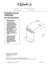
Soda Dispensing Towers
Part Number 020002777 10/11

We reserve the right to make product improvements at any time.
Specifications and design are subject to change without notice.
Safety Notices
As you work on Manitowoc equipment, be sure to pay
close attention to the safety notices in this manual.
Disregarding the notices may lead to serious injury and/
or damage to the equipment.
Throughout this manual, you will see the following types
of safety notices:
Procedural Notices
As you work on Manitowoc equipment, be sure to read
the procedural notices in this manual. These notices
supply helpful information which may assist you as you
work.
Throughout this manual, you will see the following types
of procedural notices:
NOTE: Text set off as a Note provides you with simple,
but useful, extra information about the procedure you
are performing.
Read These Before Proceeding:
NOTE: SAVE THESE INSTRUCTIONS.
!
Warning
Text in a Warning box alerts you to a potential
personal injury situation. Be sure to read the
Warning statement before proceeding, and work
carefully.
!
Caution
Text in a Caution box alerts you to a situation in
which you could damage the equipment. Be sure to
read the Caution statement before proceeding, and
work carefully.
Important
Text in an Important box provides you with
information that may help you perform a procedure
more efficiently. Disregarding this information will not
cause damage or injury, but it may slow you down as
you work.
!
Caution
Proper installation, care and maintenance are
essential for maximum performance and trouble-free
operation of your Manitowoc equipment. Read and
understand this manual. It contains valuable care
and maintenance information. If you encounter
problems not covered by this manual, do not
proceed, contact Manitowoc. We will be happy to
provide assistance.
Important
Routine adjustments and maintenance procedures
outlined in this manual are not covered by the
warranty.
!
Warning
PERSONAL INJURY POTENTIAL
Do not operate equipment that has been misused,
abused, neglected, damaged, or altered/modified
from that of original manufactured specifications.

We reserve the right to make product improvements at any time.
Specifications and design are subject to change without notice.
THIS PAGE INTENTIONALLY LEFT BLANK

We reserve the right to make product improvements at any time.
Specifications and design are subject to change without notice.

Part Number 020002777 10/11 i
Table of Contents
Section 1
General Information
Read This Manual. . . . . . . . . . . . . . . . . . . . . . . . . . . . . . . . . . . . . . . . . . . . . . . . . 1-1
Unit Inspection . . . . . . . . . . . . . . . . . . . . . . . . . . . . . . . . . . . . . . . . . . . . . . . . . . . 1-1
Model Numbers. . . . . . . . . . . . . . . . . . . . . . . . . . . . . . . . . . . . . . . . . . . . . . . . . . . 1-1
Attention: Marine Installations . . . . . . . . . . . . . . . . . . . . . . . . . . . . . . . . . . . 1-2
Outdoor Applications . . . . . . . . . . . . . . . . . . . . . . . . . . . . . . . . . . . . . . . . . . 1-2
Serial Plate Location . . . . . . . . . . . . . . . . . . . . . . . . . . . . . . . . . . . . . . . . . . . . . . 1-2
Warranty Information . . . . . . . . . . . . . . . . . . . . . . . . . . . . . . . . . . . . . . . . . . . . . . 1-2
Section 2
Installation
Dimensions and Clearances — All Models . . . . . . . . . . . . . . . . . . . . . . . . . . . . 2-1
Model 116 . . . . . . . . . . . . . . . . . . . . . . . . . . . . . . . . . . . . . . . . . . . . . . . . . . 2-1
Model 126 (V-Style) . . . . . . . . . . . . . . . . . . . . . . . . . . . . . . . . . . . . . . . . . . 2-1
Model 136 . . . . . . . . . . . . . . . . . . . . . . . . . . . . . . . . . . . . . . . . . . . . . . . . . . 2-1
Model 126 (S-Style) . . . . . . . . . . . . . . . . . . . . . . . . . . . . . . . . . . . . . . . . . . 2-1
Model 138 . . . . . . . . . . . . . . . . . . . . . . . . . . . . . . . . . . . . . . . . . . . . . . . . . . 2-2
Model 143 . . . . . . . . . . . . . . . . . . . . . . . . . . . . . . . . . . . . . . . . . . . . . . . . . . 2-2
Model 158 . . . . . . . . . . . . . . . . . . . . . . . . . . . . . . . . . . . . . . . . . . . . . . . . . . 2-2
Model 156 . . . . . . . . . . . . . . . . . . . . . . . . . . . . . . . . . . . . . . . . . . . . . . . . . . 2-2
Model 158 (High Cup Clearance) . . . . . . . . . . . . . . . . . . . . . . . . . . . . . . . . 2-3
Model 1310 (With Drain Pan) . . . . . . . . . . . . . . . . . . . . . . . . . . . . . . . . . . . 2-3
Model 1310 (No Drain Pan) . . . . . . . . . . . . . . . . . . . . . . . . . . . . . . . . . . . . 2-3
FootPrints - All Models . . . . . . . . . . . . . . . . . . . . . . . . . . . . . . . . . . . . . . . . 2-4
Model 116 . . . . . . . . . . . . . . . . . . . . . . . . . . . . . . . . . . . . . . . . . . . . . . . . . . 2-4
Model 126 (V & S-Style Towers) . . . . . . . . . . . . . . . . . . . . . . . . . . . . . . . . . 2-4
Model 136 . . . . . . . . . . . . . . . . . . . . . . . . . . . . . . . . . . . . . . . . . . . . . . . . . . 2-5
Model 138 . . . . . . . . . . . . . . . . . . . . . . . . . . . . . . . . . . . . . . . . . . . . . . . . . . 2-5
Model 143 . . . . . . . . . . . . . . . . . . . . . . . . . . . . . . . . . . . . . . . . . . . . . . . . . . 2-6
Model 156 (Left Hand Pass-Thru) . . . . . . . . . . . . . . . . . . . . . . . . . . . . . . . . 2-7
Model 156 (Right Hand Pass-Thru) . . . . . . . . . . . . . . . . . . . . . . . . . . . . . . 2-7
Model 158 . . . . . . . . . . . . . . . . . . . . . . . . . . . . . . . . . . . . . . . . . . . . . . . . . . 2-8
Model 1310 . . . . . . . . . . . . . . . . . . . . . . . . . . . . . . . . . . . . . . . . . . . . . . . . . 2-9
Safe Installation Dos and Don’ts. . . . . . . . . . . . . . . . . . . . . . . . . . . . . . . . . . . . . 2-10

Table of Contents (continued)
ii Part Number 020002777 10/11
Location Requirements . . . . . . . . . . . . . . . . . . . . . . . . . . . . . . . . . . . . . . . . . . . . 2-10
Location of the Dispensing Tower . . . . . . . . . . . . . . . . . . . . . . . . . . . . . . . . 2-10
Ratings . . . . . . . . . . . . . . . . . . . . . . . . . . . . . . . . . . . . . . . . . . . . . . . . . . . . 2-10
Kitchen Equipment Installer Representative Responsibilities . . . . . . . . . . . 2-10
Requirements . . . . . . . . . . . . . . . . . . . . . . . . . . . . . . . . . . . . . . . . . . . . . . . 2-11
Installer Instructions. . . . . . . . . . . . . . . . . . . . . . . . . . . . . . . . . . . . . . . . . . . . . . . 2-11
Preparation . . . . . . . . . . . . . . . . . . . . . . . . . . . . . . . . . . . . . . . . . . . . . . . . . 2-11
Electrical . . . . . . . . . . . . . . . . . . . . . . . . . . . . . . . . . . . . . . . . . . . . . . . . . . . . . . . . 2-11
General . . . . . . . . . . . . . . . . . . . . . . . . . . . . . . . . . . . . . . . . . . . . . . . . . . . . 2-11
Minimum Circuit Ampacity . . . . . . . . . . . . . . . . . . . . . . . . . . . . . . . . . . . . . . 2-11
Electrical Requirements . . . . . . . . . . . . . . . . . . . . . . . . . . . . . . . . . . . . . . . . 2-11
Electrical Specifications . . . . . . . . . . . . . . . . . . . . . . . . . . . . . . . . . . . . . . . . 2-11
Making the Electrical Connections . . . . . . . . . . . . . . . . . . . . . . . . . . . . . . . 2-11
Grounding Instructions . . . . . . . . . . . . . . . . . . . . . . . . . . . . . . . . . . . . . . . . 2-12
Mounting The Dispensing Tower. . . . . . . . . . . . . . . . . . . . . . . . . . . . . . . . . . . . . 2-13
Secured By Bolting To The Counter . . . . . . . . . . . . . . . . . . . . . . . . . . . . . . 2-13
Secured With Mounting Clamps . . . . . . . . . . . . . . . . . . . . . . . . . . . . . . . . . 2-13
Plumbing – General. . . . . . . . . . . . . . . . . . . . . . . . . . . . . . . . . . . . . . . . . . . . . . . . 2-14
Connecting The Syrup And Water Lines . . . . . . . . . . . . . . . . . . . . . . . . . . . 2-14
How to Insulate all the Connections . . . . . . . . . . . . . . . . . . . . . . . . . . . . . . . . . . 2-18
Section 3
Operation
Calibration of the Dispensing Valves . . . . . . . . . . . . . . . . . . . . . . . . . . . . . . . . . 3-1
Set The Flow (Water Flow Rate Only) . . . . . . . . . . . . . . . . . . . . . . . . . . . . . 3-1
Set The Ratio (Water To Syrup Mixture) . . . . . . . . . . . . . . . . . . . . . . . . . . . 3-2
Set The Volume (Drink Portion Sizes) . . . . . . . . . . . . . . . . . . . . . . . . . . . . . 3-2
Run mode . . . . . . . . . . . . . . . . . . . . . . . . . . . . . . . . . . . . . . . . . . . . . . . . . . 3-2
Program modes. . . . . . . . . . . . . . . . . . . . . . . . . . . . . . . . . . . . . . . . . . . . . . . . . . . 3-3
Program Mode CAL No. 1 (total volume) . . . . . . . . . . . . . . . . . . . . . . . . . . 3-3
Program Mode CAL No. 2 (incremental) . . . . . . . . . . . . . . . . . . . . . . . . . . . 3-3
Program Mode CAL No. 3 (Water/Soda) . . . . . . . . . . . . . . . . . . . . . . . . . . . 3-3
Top-off program mode . . . . . . . . . . . . . . . . . . . . . . . . . . . . . . . . . . . . . . . . . 3-4
Test And Sanitation Mode . . . . . . . . . . . . . . . . . . . . . . . . . . . . . . . . . . . . . . 3-4
Instructions For Dual Flavor Stations . . . . . . . . . . . . . . . . . . . . . . . . . . . . . 3-4
Entering Water/soda Programming Mode . . . . . . . . . . . . . . . . . . . . . . . . . . 3-4
Equipment Setup and Close Procedure . . . . . . . . . . . . . . . . . . . . . . . . . . . . . . . 3-4
Equipment Setup Procedure . . . . . . . . . . . . . . . . . . . . . . . . . . . . . . . . . . . . 3-4
Equipment Close Procedure . . . . . . . . . . . . . . . . . . . . . . . . . . . . . . . . . . . . 3-4

Table of Contents (continued)
Part Number 020002777 10/11
iii
Section 4
Maintenance
Maintenance Schedule. . . . . . . . . . . . . . . . . . . . . . . . . . . . . . . . . . . . . . . . . . . . . 4-1
Periodic Maintenance Listed By Major Components . . . . . . . . . . . . . . . . . 4-1
Periodic Maintenance Listed By Scheduled Frequency . . . . . . . . . . . . . . . 4-2
Cleaning & Sanitizing The Dispensing Valves And Product Lines . . . . . . . 4-3
Cleaning Equipment and Supplies . . . . . . . . . . . . . . . . . . . . . . . . . . . . . . . . . . . 4-3
Sanitizing. . . . . . . . . . . . . . . . . . . . . . . . . . . . . . . . . . . . . . . . . . . . . . . . . . . . . . . . 4-4
Beverage System Cleaning . . . . . . . . . . . . . . . . . . . . . . . . . . . . . . . . . . . . 4-4
Bag-In-Box System Sanitation . . . . . . . . . . . . . . . . . . . . . . . . . . . . . . . . . . 4-4
Figal Beverage System . . . . . . . . . . . . . . . . . . . . . . . . . . . . . . . . . . . . . . . . 4-5
Shipping, Storage and Relocation . . . . . . . . . . . . . . . . . . . . . . . . . . . . . . . . . . . 4-6
Section 5
Before Calling for Service
Checklist . . . . . . . . . . . . . . . . . . . . . . . . . . . . . . . . . . . . . . . . . . . . . . . . . . . . . . . . 5-1
No syrup or insufficient syrup in finished drink . . . . . . . . . . . . . . . . . . . . . . 5-1
No carbonated water or insufficient carbonated water in finished drink . . . 5-2
No water or insufficient water in finished drinks . . . . . . . . . . . . . . . . . . . . . 5-2


Part Number 020002777 10/11 1-1
Section 1
General Information
Read This Manual
Manitowoc Food Service developed this manual as a
reference guide for the owner/operator and installer of
this equipment. Please read this manual before
installation or operation of the machine. A qualified
service technician must perform installation and start-up
of this equipment, consult Section 5 within this manual
for service assistance.
If you cannot correct the service problem, call your
Manitowoc Beverage Equipment (MBE) Service Agent
or Distributor. Always have your model and serial
number available when you call.
Your Service Agent ____________________________
Service Agent Telephone Number_________________
Your Local MBE Distributor ______________________
Distributor Telephone Number____________________
Model Number _______________________________
Serial Number ________________________________
Installation Date ______________________________
Unit Inspection
Thoroughly inspect the unit upon delivery. Immediately
report any damage that occurred during transportation to
the delivery carrier. Request a written inspection report
from a claims inspector to document any necessary
claim.
Model Numbers
This manual covers the following models:
!
Warning
PERSONAL INJURY POTENTIAL
Do not operate equipment that has been misused,
abused, neglected, damaged, or altered/modified
from that of original manufactured specifications.
Soda Tower Models
116, 126CNK. 126ENK, 126LNK, 126LDP, 126LDPX,
136, 136PDP, 136PDPX, 138CDA, 136LDAX,
136EDLVX, 136LDLX, 138EDSX, 138EDSX, 138DS,
138LDAX, 138CDAL, 138PDLX, 138PDP, 138PDPX,
136FDL, 136FDP, 136FDS, 136EDL, 136FDL, 136FDP,
136FDS, 136LDAL, 136LDL, 138FDL, 138FDP,
138FDS, 138EDL, 138FDL, 138FDP, 138FDS,
138LDAL, 138LDL, EDA, FDA, LDA, 143LDAX,
143EDA, 143EDAX, 146, 146 Quad Control, 156,
156PDP, 156PDPX, 156EDL, 156EDRA, 156FDAX,
Pass-Thru, Quad Control, 156 Pass-Thru, 158FDLHX,
158LDLHX, 158PDPLH, 158PDPLHX, 158LDLHX,
1310EDC, 1310ENS, 1310LVD, 1310PDL, 1310PDP,
1510EDLH, 1510LDLHX

General Information Section 1
1-2
Part Number 020002777 10/11
ATTENTION: MARINE INSTALLATIONS
NOTE: This unit must be secured to the vessel during
installation.
OUTDOOR APPLICATIONS
TS Multiplex Beverage Recirculating units are approved
and listed by Underwriters Laboratories (UL). However
they are not UL approved for weather exposure
applications. These units must be installed in areas
where adequate protection from the elements is
provided, all other models are ETL listed.
Serial Plate Location
Warranty Information
Consult your local MBE Distributor for terms and
conditions of your warranty. Your warranty specifically
excludes all beverage valve brixing, general
adjustments, cleaning, accessories and related
servicing.
Your warranty card must be returned to MBE to activate
the warranty on this equipment. If a warranty card is not
returned, the warranty period can begin when the
equipment leaves the MBE factory.
No equipment may be returned to MBE without a written
Return Materials Authorization (RMA). Equipment
returned without an RMA will be refused at MBE’s dock
and returned to the sender at the sender’s expense.
Please contact your local MBE distributor for return
procedures.
!
Warning
This unit is for use on vessels over 66 ft (20 m) in
length. This unit must not be installed in the engine
space of a gasoline-powered ship.


Installation Section 2
2-10
Part Number 020002777 10/11
Safe Installation Dos and Don’ts
• DO adhere to all National and Local Plumbing and
Electrical Safety Codes.
• DO turn OFF incoming electrical service switches
when servicing, installing, or repairing equipment.
• DO check that all flare fittings are tight. This check
must be performed with a wrench to ensure a quality
seal.
• DO inspect pressure on regulators before starting up
equipment.
• DO protect eyes when working around refrigerants.
• DO use caution when handling metal surface edges
of all equipment.
• DO handle CO
2
cylinders and gauges with care.
Secure cylinders properly against abrasion.
• DO store CO
2
cylinder(s) in well ventilated areas.
• DO NOT exhaust CO
2
gas (example: syrup pump)
into an enclosed area, including all types of walk-in
coolers, cellars, and closets.
• DO NOT throw or drop a CO
2
cylinder. Secure the
cylinder(s) in an upright position with a chain.
• DO NOT connect the CO
2
cylinder(s) directly to the
product container. Doing so will result in an explosion
causing possible death or injury. It is best to connect
the CO
2
cylinder(s) to a regulator(s).
• DO NOT store CO
2
cylinders in temperature above
125°F (51.7°C) near furnaces, radiator or sources of
heat.
• DO NOT release CO
2
gas from old cylinder.
• DO NOT touch refrigeration lines inside units; some
may exceed temperatures of 200°F (93.3°C).
NOTICE: All utility connections and fixtures must be
sized, installed, and maintained in accordance with
Federal, State, and Local codes.
Location Requirements
LOCATION OF THE DISPENSING TOWER
1. Determine the location where the Multiplex
Dispensing Tower will be installed.
2. Locate the mounting template provided with the
tower installation kit.
3. Using the mounting template as a guide, punch out
the required holes in the counter top.
RATINGS
NOTE: Refer to nameplate on side of unit for voltage
and amperage specifications. Optional equipment may
require additional power supplies.
KITCHEN EQUIPMENT INSTALLER
REPRESENTATIVE RESPONSIBILITIES
Prior to scheduling Multiplex Equipment installer,
the following steps listed below must be completed:
1. Usable floor sewer drain.
2. Refer to electrical requirement chart for your model.
3. Usable potable water.
4. CO
2
Gas (bulk or bottled supply); minimum 3/8" line.
5. One 5 gallon (19 L) container or Bag-In-Box
container of each post mix syrup flavor.
6. A 120 VAC, 3-wire, 1 Phase, 60 Hz dual wall
receptacle for optional electrical equipment
(domestic only).
NOTE: Do not schedule the authorized Multiplex
Equipment Installer until all of the above have been
completed. It will only result in charge-backs to you for
the unnecessary trips.
!
Warning
Read the following warnings before beginning an
installation. Failure to do so may result in possible
death or serious injury.
!
Warning
Carbon Dioxide (CO
2
) displaces oxygen. Exposure
to a high concentration of CO
2
gas causes tremors,
which are followed rapidly by loss of consciousness
and suffocation. If a CO
2
gas leak is suspected,
particularly in a small area, immediately ventilate the
area before repairing the leak. CO
2
lines and pumps
must not be installed in an enclosed space. An
enclosed space can be a cooler or small room or
closet. This may include convenience stores with
glass door self serve coolers. If you suspect CO
2
may build up in an area, venting of the BIB pumps
and/or CO
2
monitors must be utilized.
/