Page is loading ...

Kit Features:
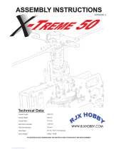
Specifications:
Lightweight yet extremely strong G10 or carbon fiber frames.
High gloss large diameter 25mm tail boom with belt drive system.
Blade grips accommodate blades 12mm (LT) to 18mm (HD) blade roots.
300 mL fuel tank for long engine run time.
Convenient and easy access to spark plug.
Triple bearing supported blade grips and tail blade grips.
Machined center dual ball bearing swashplate for 120 degree CCPM.
Adjustable bell-hiller ratio allows tuning for preferred cyclic response (HD)
Tunable flight characteristics for stability or speed.
Length: 1366mm
Height: 381mm
Width: 260mm
Main rotor diameter: 1435mm
Tail rotor diameter: 262mm
Main rotor blades: 600mm-640mm
Tail rotor blades: 95mm
Version 1.10
© 2010 Century Helicopter Products - All rights reserved.

Radikal Gasser
Page 2
INTRODUCTION
Warning
This radio controlled model is not a toy! It is a precision machine requiring proper assembly and setup to avoid accidents. It is the
responsibility of the owner to operate this product in a safe manner as it can inflict serious injury otherwise. It is recommended that if
you are in doubt of your abilities, seek assistance from experienced radio control modelers and associations. Keep loose items that can
get entangled in the rotor blades away for the main and tail blades, including loose clothing, hair, or other objects such as pencils and
screwdrivers. Especially keep your hands away from the rotor blades. As manufacturer, we assume no liability for the use of this product.
Pre-assembly Information
.launam eht fo snoitces eht ot dnopserroc hcihw ylbmessa fo esae rof deggab era strap tnenopmoc rojam eht lla ,tik eht gninepo nopU
Various assemblies have been pre-assembled however, only as a reference assembly. Final assembly is up to the user. Installation onto
the particular parts, screws and nuts required for each step are packaged in the same bag as the parts. Be careful when opening each
bag as not to lose any hardware. Care has been taken in filling and packing of each bag however mistakes do happen. If there is a parts
shortage or missing hardware please contact us at:
General Guidelines
Apply thread lock to all metal to metal thread contact points. Do not apply CA (cyanoacrylate) glue or thread lock to ny-lock nuts (metal nuts
with plastic inserts). Diagrams indicated by bounding boxes for screws, bearings, etc. are illustrated at a 1-to-1 ratio. All other illustrations
are not drawn to scale. Throughout this manual, you will find building tips. Please follow the tips and use common sense when building.
Century Helicopter Products
1740-C Junction Ave.
www.centuryheli.com
Flight Guidelines
Please note this checklist is not intended to be a replacement for the content included in this instruction manual. Although it can
be used as a quick start guide, we strongly suggest reading through this manual completely before proceeding.
Always turn the transmitter on first
Allow the gyro, and receiver to arm and initialize properly
Do a pre-flight check making sure all electronics are working and look for any mechanical issues
Fly the model
Land the model
Turn off the engine
Always turn the transmitter off last
San Jose, CA. 95112
Thank You
Congratulations on the purchase of the latest Century Gasser series, the Radikal G20. You’re about to build one of the world’s first fully
functional 3D aerobatic helicopters powered by the Zenoah 20cc gasoline engine. Be sure to read through and follow the instructions
during the build.

Radikal Gasser
Page 3
CN2050
PADDLE GAUGE
CN2034A
BALL LINK PLIERS
HOBBY KNIFE
RECEIVER BATTERY
SERVOS X 5
ZIP TIES
4-WAY WRENCH
GYRO
6 CHANNEL RECEIVER
(MINIMUM)
HOBBY SCISSORS
METRIC RULER OR
SIMILAR MEASURING
DEVICE
6 CHANNEL
CCPM TRANSMITTER
(MINIMUM)
CN2027
G-FORCE PITCH GAUGE
CN2051
ACCURATECH BLADE BAL-
ANCER V.2
CN2255
CONTROL ROD
SETUP GAUGE
NEEDLE NOSE
PLIERS
SYNTHETIC
OIL/GREASE
1.000
87 TO 92 OCTANE
GASOLINE
600MM TO 660MM
MAIN ROTOR BLADES
20CC ZENOAH
GASOLINE ENGINE
CN3070
20cc TORPEDO
GASSER TUNED
MUFFLER
2-STROKE
MOTOR OIL
SLOW &
Medium CA
GLUE
Medium
(Medium)
THREAD-
LOCK
DREMEL TOOL
OR SIMILAR
REQUIRED ITEMS
Century Helicopter Products warranties that the Products purchased (the “Product”) will be free from defects in materials and workman-
ship 30 days from the date of purchase by the Purchaser.
Warranty Period
(a) This warranty is limited to the original customer (“Purchaser”) and is not transferable. REPAIR OR REPLACEMENT AS PROVIDED
UNDER THIS WARRANTY I S THE EXCLUSIVE REMEDY OF T HE P URCHASER. This warranty covers only those Products purchased
from an authorized Century Helicopter Products dealer. Third party transactions are not covered by this warranty. Proof of purchase is
required for warranty claims. Further, Century Helicopter Products reserves the right to change or modify this warranty without notice
and disclaims all other warranties, express or implied.
(b) Limitations- CENTURY HELICOPTER PRODUCT MAKES NO WARRANTY OR REPRESENTATION, EXPRESS OR IMPLIED, ABOUT NON-
INFRINGEMENT, MERCHANTABILITY OR FITNESS FOR A PARTICULAR PURPOSE OF THE PRODUCT. THE PURCHASER ACKNOWLEDG-
ES THAT THEY ALONE HAVE DETERMINED THAT THE PRODUCT WILL SUITABLY MEET THE REQUIREMENTS OF THE PURCHASER’S
INTENDED USE.
(c) Purchaser Remedy- Century Helicopter Products’s sole obligation hereunder shall be that Century Helicopter Products will, at its
option, (i) repair or (ii) replace, any Product determined by Century Helicopter Products to be defective. In the event of a defect, these
are the Purchaser’s exclusive remedies. Century Helicopter Products reserves the right to inspect any and all equipment involved in
a warranty claim. Repair or replacement decisions are at the sole discretion of Century Helicopter Products. This warranty does not
cover cosmetic damage or damage due to acts of God, accident, misuse, abuse, negligence, commercial use, or modification of or to any
part of the Product. This warranty does not cover damage due to improper installation, operation, maintenance, or attempted repair by
anyone other than Century Helicopter Products. Return of any goods by Purchaser must be approved by Century Helicopter Product s
before shipment.
Limited Warranty
1.000
CN2031
CN2017
HEX DRIVERS
1.5, 2.0, 2.5, 3.0, 4.0, 5.0
ELECTRONIC
I G N I T I O N
BATTERY

Radikal Gasser
Page 4
AMA RULES & REGULATIONS
1) I will not fly my model aircraft in sanctioned events, air shows or model flying demonstrations until it has been proven to be airwor-
thy by having been previously, successfully flight tested.
2) I will not fly my model higher than approximately 400 feet within 3 miles of an airport without notifying the airport operator. I will
give right-of-way and avoid flying in the proximity of full-scale aircraft. Where necessary, an observer shall be utilized to supervise flying
to avoid having models fly in the proximity of full-scale aircraft.
3) Where established, I will abide by the safety rules for the flying site I use, and I will not willfully or deliberately fly my models in a
careless, reckless and/or dangerous manner.
4) The maximum takeoff weight of a model is 55 pounds, except models flown under Experimental Aircraft rules.
5) I will not fly my model unless it is identified with my name and address or AMA number on or in the model. (This does not apply to
models while being flown indoors.)
6) I will not operate models with metal-bladed propellers or with gaseous boosts, in which gases other than air enter their internal
combustion engine(s); nor will I operate models with extremely hazardous fuels such as those containing tetranitromethane or hy-
drazine.
1) I will have completed a successful radio equipment ground range check before the first flight of a new or repaired model.
2) I will not fly my model aircraft in the presence of spectators until I become a qualified flier, unless assisted by an experienced helper.
3) At all flying sites a straight or curved line(s) must be established in front of which all flying takes place with the other side for
spectators. Only personnel involved with flying the aircraft are allowed at or in front of the flight line. Intentional flying behind the flight
line is prohibited.
4) I will operate my model using only radio control frequencies currently allowed by the Federal Communications Commission. (Only
properly licensed Amateurs are authorized to operate equipment on Amateur Band frequencies.)
5) Flying sites separated by three miles or more are considered safe from site-to site interference, even when both sites use the
same frequencies. Any circumstances under three miles separation require a frequency management arrangement, which may be
either an allocation of specific frequencies for each site or testing to determine that freedom from interference exists. Allocation
plans or interference test reports shall be signed by the parties involved and provided to AMA Headquarters. Documents of agree-
ment and reports may exist between
(1) Two or more AMA Chartered Clubs, (2) AMA clubs and individual AMA members not associated with AMA Clubs, or (3) two or
more individual AMA members.
6) For Combat, distance between combat engagement line and spectator line will be 500 feet per cubic inch of engine displacement.
(Example: .40 engine = 200 feet.); electric motors will be based on equivalent combustion engine size. Additional safety requirements
will be per the RC Combat section of the current Competition Regulations.
7) At air shows or model flying demonstrations, a single straight line must be established, one side of which is for flying, with the
other side for spectators.
8) With the exception of events flown under AMA Competition rules, after launch, except for pilots or helpers being used, no powered
model may be flown closer than 25 feet to any person.
9) Under no circumstances may a pilot or other person touch a powered model in flight.
General
Radio Control

Radikal Gasser
Page 5
HEAD ASSEMBLY (HD VERSION)
1
2
3
4
5
6
Take special care when pressing in these bearings. Do not
press in on the inner sleeve of the bearing
7
8
9
10
Do not secure all the screws until lining up the
components in the following steps.
CNBB0730
CNBB0840
HI3167G
CNM3X14BHCS
CNM3X6BHCS
CNM2.5X8CS
Insert one ball bearing into each bearing cup and insert into
the offset plate. Apply one small drop of slow cyanoacrylate
glue (Slow CA) to the joint between the backside of the
bearing cup and the offset plate. Insert one ball
bearing into each tie bar. Using an available
M3 socket cap screw, form threads
into both ends of the tie
bars. Insert one
M3x6 button head
screw through
the right side
hole of the
offset plate
and thread
into one
tie bar.
M a k e
t w o
i d e n t i c a l
s u b a s s e m -
blies . Note that
the bearing cups face
outwards from the head
block. Insert one M3x14 but-
ton head screw through the tie
bar bearing, slide one steel spacer
and carefully apply Medium threadlock to
the exposed threads and insert into the right
side of the head block. Do not overtighten. Repeat
for the second sub-assembly. Once complete apply
a small amount of slow cyanoacrylate glue and insert one
CNLR1020 special long thread ball into each offset plate to com-
plete the assembly.
Do not open all the bags prior to starting assembly. Open the bags step by step as you go through the instruction manual. The
components are bagged to make assembly easier. The next few pages will pertain to the assembly of the head. Please follow
the instructions based on the head type you own. Make sure to apply threadlock to any screws going into metal.
BAG 1
No.
Description
Qty
1
2
3
4
5
Part #
6
7
8
9
10
NX Rotor Head Yoke(主旋翼中心座)
Seesaw Tie Bar Set( 平衡杆控制臂)
2
2
2
2
2
2
CNBB0730
CNBB0840
HI3167B
HI3167G
CNM3X14BHCS
HI3167G
2
2
1
HI6160A
CNM3X6BHCS
CNM2.5X8CS
2
Stainless Ball, 3mm Thread, Medium(M3球头螺丝)
Seesaw Offset Plates( 平衡杆固定片)
3x7x3 Ball Bearing( 轴承)
M3x6 Button Head Cap Screws( 伞头螺丝)
4x8x3 Ball Bearing( 轴承)
3x5x6 Seesaw Tie Bar Set( 铁套)
M3x14 Button Head Cap Screws( 伞头螺丝)
M2.5x8 Cap Screws( 杯头螺丝)
CNLR1017 L=6.5MM
CNLR1017

Radikal Gasser
Page 6
HEAD ASSEMBLY (LT VERSION)
Do not secure all the screws until lining up the
components in the following steps.
Insert one ball bearing into each bearing cup and insert into
the offset plate. Apply one small drop of slow cyanoacrylate
glue (Slow CA) to the joint between the backside of the
bearing cup and the offset plate. Insert one ball
bearing into each tie bar. Using an available
M3 socket cap screw, form threads
into both ends of the tie
bars. Insert one
M3x6 button head
screw through
the right side
hole of the
offset plate
and thread
into one
tie bar.
Make two identical
subassemblies . Note
that the bearing cups
face outwards from the head
block. Insert one M3x14 but-
ton head screw through the tie bar
bearing, slide one steel spacer and care-
fully apply Medium threadlock to the exposed
threads and insert into the right side of the head
block. Do not overtighten. Repeat for the second
sub-assembly. Once complete apply a small amount of
slow cyanoacrylate glue and insert one CNLR1020 special
long thread ball into each offset plate to complete the assembly.
Do not open all the bags prior to starting assembly. Open the bags step by step as you go through the instruction manual. The
components are bagged to make assembly easier. The next few pages will pertain to the assembly of the head. Please follow
the instructions based on the head type you own. Make sure to apply threadlock to any screws going into metal.
1
2
3
4
6
5
7
9
8
CNLR1017 L=6.5MM
3x5x7.5
CNM3x6BHCS
CNM3x14BHCS
CNBB48
CNBB37
Take special care when pressing in these bearings. Do not
press in on the inner sleeve of the bearing
BAG 1
No.
Part #
Description
1
2
3
4
6
7
Qty
5
8
9
2
Button Head Screw( 圆头螺丝)M3x6
CNM3x6BHCS
2
2
Bearing(滚珠轴承)4x8x3
CNBB48
2
2
Bearing(滚珠轴承)3x7x3
CNBB0730
Seesaw Offset Plate(平衡杆控制器)
HI3167B
2
HI3167S
HI3167G
Seesaw Offset Plate 2(平衡杆控制器2)
2
2
Button Head Screw( 圆头内六角螺丝)M3x14
CNM3x14BHCS
Head Block(主旋翼中心座)
HI6160A
1
3x5x7.5 Seesaw Tie Bar Set(
铁套)
Stainless Ball, 3mm Thread, Medium(M3球头螺丝)
CNLR1017

Radikal Gasser
Page 7
HEAD ASSEMBLY (HD VERSION)
Pushrod assembly (parts 2 through 4) is already assembled but check that the length is
actually 43mm (center to center). As the pushrods are built and installed they should be
checked for tightness. Press one ball link onto each double studded steel ball, making sure
that pressure is applied from the side of the ball link with circle mark. While holding one fly-
bar control arm, apply a small amount of slow cyanoacrylate glue and thread one end of the
double studded steel ball into each standoff. When it becomes difficult to turn with fingers,
apply slow CA to the threads and start screwing in the tapered control arm stand-off on
the other end of the ball. Slide and center the flybar through the head assembly. Care-
fully look at the flybar control arm assemblies from the previous step and notice
that when installed correctly, the securing set screw is on top. Insert one
M4x6x0.5 micro washer #CNLR1006 against each bearing then slide
the control arm halves onto each side, so that they match togeth-
er and the set screw remains on top. Insert one M3x12 but-
ton head socket screw to secure the opposite standoff.
Hold the tapered standoff using pliers while tight-
ening the screw as the rotor head
rotates clockwise.
Apply a small amount of cya-
noacrylate glue to the special
long thread ball.
All ball links are molded to be in-
stalled in only one direction. Look
carefully at the hole for the ball
as that side is 1mm larger .
Loosely tighten the M4x5 set screws into the round aluminum inserts aligned with the flat spots on the flybar. Tighten both set screws, one
at a time using Medium threadlock. Make a pencil mark 5mm past the threads on both ends of the flybar. Thread the flybar paddles onto the
flybar until the mark is reached and align the paddles parallel. Again using the ruler, rotate one paddle or the other to get equal distances while
remembering the leading edge of the paddles turn clockwise.
NOTICE SIZE OF HOLES ON BALL LINKS
THE SIDE WITH THE SMALLER HOLE
SHOULD FACE OUTWARDS
1
2
3
4
5
6
7
8
9
10
Make sure the distance on
both sides are equal
Make sure the distance on
both sides are equal
BAG 1
No.
Description
Qty
1
2
3
4
5
Part #
6
7
8
9
10
2
2
2
2
2
2
CNM4X5SS
CNM3X12BHCS
2
1
2
HI3176C
HI3176C
HI3176C
HW3173A
HI6179B
HI6145
HW6192
Flybar Paddles( 平衡翼)
4mm Flybar 500mm(
平衡杆)
M4x5 Socket Head Set Screw( 无头内六角螺丝)
Pushrod Set( 拉杆)
Flybar Arms(
Flybar Arms(
Flybar Arms(
平衡翼控制臂)
球头双牙螺丝)
Ball Link Set(球头连接头)
M3x12 Button Head Cap Screws( 圆头螺丝)
CNLR1006
M4X6X0.5 Washer( 平面垫片)
2
平衡翼控制臂)
CNM3X12BHCS
CNM4X5SS
C
A
HW3176C

Radikal Gasser
Page 8
HEAD ASSEMBLY (LT VERSION)
Pushrod assembly (parts 2 through 4) is already assembled but check that the length is
actually 43mm (center to center). As the pushrods are built and installed they should be
checked for tightness. Press one ball link onto each double studded steel ball, making sure
that pressure is applied from the side of the ball link with circle mark. While holding one
flybar control arm, apply a small amount of slow cyanoacry-
late glue and thread one end of the double studded steel ball
into each standoff. When it becomes difficult to turn with fin-
gers, apply slow CA to the threads and start screwing in the
tapered control arm stand-off on the other end of the ball.
Slide and center the flybar through the head assembly. Care-
fully look at the flybar control arm assemblies from the previ-
ous step and notice that when installed correctly, the secur-
ing set screw is on top. Insert one M4x6x0.5 micro washer
#CNLR1006 against each bearing then slide the control
arm halves onto each side, so that
they match together and the set
screw remains on top. Insert one
M3x12 button head socket screw
to secure the opposite standoff.
Hold the tapered standoff using
pliers while tightening the screw
as the rotor head rotates clock-
wise.
Loosely tighten the M4x5 set screws into the round aluminum inserts aligned with the flat spots on the flybar. Tighten both set screws, one
at a time using Medium threadlock. Make a pencil mark 5mm past the threads on both ends of the flybar. Thread the flybar paddles onto the
flybar until the mark is reached and align the paddles parallel. Again using the ruler, rotate one paddle or the other to get equal distances while
remembering the leading edge of the paddles turn clockwise.
NOTICE SIZE OF HOLES ON BALL LINKS
THE SIDE WITH THE SMALLER HOLE
SHOULD FACE OUTWARDS
Make sure the distance on
both sides are equal
Make sure the distance on
both sides are equal
1
4
5
7
6
8
9
10
3
2
CNM3X12BHCS
CNM4X5SS
2
4
Seesaw Tie Bars( 稳定翼控制臂)
2
2
Pushkod Set(拉杆)
Ball Link Set(26 Long,4 Short)( 球头连接头)
Washer 4x6x0.5( 平面垫片)
M3 Two-tooth Screw Ball( M3球头双牙螺丝)
2
No.
Description
Qty
1
2
3
4
5
Part #
6
M4x5 Socket Head Set Screw (无头内六角螺丝)
7
8
9
10
Seesaw Tie Bars( 平衡杆控制臂)
M3x12 Button Head Cap Screws( 圆头内六角螺丝)
Flybar Paddles( 平衡片)
HI3167C
HI6145
Hw6192
HI3167C
CNLR1006
CNM4X5SS
HI3167C
CNM3X12BHCS
HI6179B
2
2
2
2
1
(平衡杆)
HW6173A
4mm FLYBAR 500mm
BAG 1
C
A
HW3176C

Radikal Gasser
Page 9
HEAD ASSEMBLY (HD VERSION)
There are two types of dampeners provided. The hard black plastic dampeners
(HI6520A) should only be used for hard 3D flying. Press in the head dampers
into the rotor head block. Lubricate the inside surface of each damper with light
oil. Press one M8x16 ball bearing into both ends of each main rotor blade grip.
Slide one M14 thrust washer against the bearing closest
to the main rotor blade. Make sure that the bearing and
the thrust washer are properly seated into the deep
end of the blade grip. If necessary use a socket
that matches the outside diameter of the
bearing and press into position. The 8x13
washer/spacer (#15) is used to adjust
tightness of the head. If the head is
binding after tightening the M5
bolt (#6), remove one or more
spacers from each side. Make
two assemblies.
BELL MIXER RATIOS STYLE
BAG 1
6
7
8
9
10
11
12
13
16
15
14
HW6205
CNLR1020
CNBB0730
CNLR1014
CNM5X10CS
HW6180A
CNBB715T
CNBB816
M3X18CS
CNM3X6BHCS
Press one M3x7 flanged ball
bearing into one side followed
by one M3x5 spacer and another
flanged bearing from the opposite side.
If the bearing is tight, lightly sand the bell
mixer and use Red threadlock to bond the
bearing in place. Install the CNLR1014 short
steel ball into the single hole side of the bell mixer
and install the CNLR1020 medium steel ball using
Blue threadlock. Install the medium steel ball accord-
ing to the table to suit your flying preference. Use the
center hole for sport flying. Make two assemblies.
Using an available M3 screw, carefully form the
threads in the blade grip arm. Slide the M3x18
special socket shoulder screw through the bell
mixer arm from the flat side, add one M3x5x3
spacer and apply a drop of Slow Cyanoacrylate
glue or Epoxy glue to the end of the threads
before installing into the blade grip. Tight-
en the bolt until there is no end to
end movement, but do not
overtighten the bolt as
you can strip out the
hole. Make two as-
semblies.
BELL MIXER RATIOS STYLE
3D1:1.6
1:1.3
1:1
3D & SPORT
SPORT & FAI
Do not over-
tighten as you
can strip the
blade grip.
3
4
5
2
1
LARGER ID TOWARDS THE GRIP
SIDE PROFILE - BLADE GRIP
RECESSED CREVICE FACES MAIN SHAFT
THRUST BEARING INSTALLATION GUIDE
GROOVES INSIDE
17
1
2
3
4
5
6
7
8
9
10
11
12
13
14
2
2
2
4
2
2
2
2
2
2
2
2
2
15
16
(主桨控制臂)
(垫圈)
(M3球头螺丝)
CNBB0730
(轴承)
(M3球头螺丝)
(有头内六角螺丝)
(垫圈)
(止推轴承)
(轴承)
(主旋翼夹片)
(垫圈)
(有头内六角螺丝)
(平面垫片)
(平面垫片)
(轴承)
HI6189
HW6205
CNLR1020
CNLR1014
CNM5X10CS
HW6180A
CNBB715T
HW6182
HW6182
CNBB816
HI6184A
HW6205
CNM3x18CS
CNBB816
2
HI6181B
2
17
4
A
(平面垫片)
4
6
M5X8X15
HW6183
HW6183
7
HW6182
8X13
HW6182
8X15
NX Main Rotor Blade Grips
M3x5x3 Spacer
M3x18 Socket Head Cap Screws
8x15 Head Shim Set
8x13 Head Shim Set
8x16x5 Bearing
Hard Head Dampeners Black
8x16x5 Bearing
QtQt yy
Enhanced Metal Bell Mixer Set
M5x10 Socket Head Cap Screws
3x7x3 Ball Bearing
M5x8x15 Head Shim Set
M3x5x3 Spacer
M5x10x1 Feathering Shaft with Center Ball
Stainless Ball, 3mm Thread, Short
Stainless Ball, 3mm Thread, Medium
7x15x5 Blade Grip Thrust Ball Bearing
No No.
Descriptio Description n
Part # Part #
Standard Head Dampeners Red
HI6181A
17

Radikal Gasser
Page 10
HEAD ASSEMBLY (LT VERSION)
Press one M3x7 ball bear-
ing into one side followed by one
M3x5 spacer and another flanged
bearing from the opposite side. Install the
CNLR1014 short steel ball into one side of the
bell mixer and install the CNLR1020 medium steel
ball on the opposite side. Secure using
Slow Cyanoac-
rylate glue. Make two assemblies.
Press in the head dampers into the rotor head block. Lubricate the inside surface
of each damper with light oil. Press one M9X13 flat washer into the end of each
blade grip. If necessary use a socket that matches the diameter of the washer
and press into position. Then press in one M7X13 ball bearing into both ends
of each main rotor blade grip. Slide one M9 thrust washer against the bear-
ing closest to the main rotor blade. Make sure that the bearing and the thrust
washer are properly seated into the deep end of the blade grip. If necessary use
a socket that matches the outside diameter of the bearing and press into posi-
tion. Torque down on the M5 locknut (#1) until snug making sure the grip
still turns without binding. If you tighten down too much, you will crush
the thrust bearings. If this happens, you will need to replace the
thrust bearings. Make two assemblies.
LARGER ID TOWARDS THE GRIP
SIDE PROFILE - BLADE GRIP
RECESSED CREVICE FACES MAIN SHAFT
THRUST BEARING INSTALLATION GUIDE
GROOVES INSIDE
1
3
2
5
4
6
7
8
9
11
12
13
10
14
15
3
9x13x1
3x5x3
CNBB1370T
CNM5LOCK
CNM3x14BHSC
M3 CNLR1014
M3 CNLR1016A
CNBB0730
CNBB1360
3x5x0.5
2
M5 Locknut(M5 防松螺母)
CNM5LOCK
2
CNBB1370T
Thrust Ball Bearing(止推轴承)7x13x4.5
4
8
CNBB1370
Bearing(滚珠轴承)7x13x4
Washer(垫片)9x13x1
2
Main Rotor Blade Grip(主桨夹片)
HI3184
1
2
2
Spacer(铝套)
Dampener
R
ubber(橡胶圈)
7mm Feathering S haft(横轴)
HI6181B
2
4
Spacer(铁套)3x5x3
Bearing(滚珠轴承)3x7x3
CNBB0730
CNLR1014
2
M3 Linkage Ball(M3 球头螺丝牙长3.5mm)
HI3189A
Bell Mixer Arm(混控臂)
2
CNM3x14BHSC
2
Buton Head Socket Screw( 圆头内六角螺丝)M3x14
CNLR1016A
2
M3 Long Linkage Ball(M3 球头螺丝球头12mm)
2
Washer(垫片)3x5x0.5
CNLR1003
CNM9X13FW
HW6180S
HW6180C
No.
Description
Qty
1
2
3
4
6
7
5
8
9
10
12
13
11
14
15
HW6205
Part #
Using an available M3 screw, carefully form the
threads in the blade grip arm. Slide the M3x18
button head cap screw through the bell mixer arm
from the flat side, add one M3x5x0.5 micro washer
and apply a drop of Slow Cyanoacrylate glue to the
end of the threads before installing into the blade
grip. Tighten the bolt until there is no end to end
movement, but do not overtighten the bolt as you
can strip out the hole. Make two assemblies.
Do not over-
tighten as you
can strip the
blade grip.
BAG 1
C
A
Do not apply threadlock to
the nylock nut!
Red dampener is used for normal flight #HI6181A. Black
dampeners are used for 3D flight #HI6181B.

Radikal Gasser
Page 11
HEAD ASSEMBLY (HD VERSION)
Slide the washout guide and the rotor head onto
the main shaft. Insert the M4x22 shoulder socket
cap screw through the rotor head hub and main
shaft and secure with one M4 locknut, torque
down the screw. Apply Medium threadlock to the
M2.5x8 socket cap screws and tighten into the
bottom of the rotor head block to clamp against
the main shaft, do not over torque. Position the
washout guide against the collar and align one
hole to the vertical slot in the rotor head. Apply
Medium threadlock to the M3x4 set screws and
evenly tighten set screws in place.
1
2
3
4
5
6
Do not apply CA or
thread lock to lock nut!
M3x4
M4x22
M2.5x8
M4防松螺母
BAG 1
Do not over-tighten!
No.
Description
Qty
1
2
3
4
5
6
Part #
1
2
1
1
1
Aluminum Washout Guide( 剪型臂导柱)
CNM3x4SS
HW6053A
M4 Lock-nut(M4 螺母)
HI6153
10mm Main Shaft( 主轴)
CNM4LOCK
CNM4x22CS
M3x4 Socket Head Set Screw( 无头内六角螺丝)
M4x22 Cap Screws( 杯头内六角螺丝)
2
CNM2.5x8CS
Cap Screw(杯头内六角螺丝)M2.5x8

Radikal Gasser
Page 12
HEAD ASSEMBLY (LT VERSION)
Slide the washout guide and the rotor head onto
the main shaft. Insert the M3X18 shoulder
socket cap screw through the rotor head
hub and main shaft and secure with one
M3 locknut, torque down the screw. Apply
Medium threadlock to the M2.5x8 sock-
et cap screws and tighten into the bot-
tom of the rotor head block to clamp
against the main shaft, do not over-
torque. Position the washout guide
against the collar and align one
hole to the vertical slot in the rotor
head. Apply Medium threadlock to
the M3x4 set screws and evenly
tighten set screws in place.
CNM2.5x8CS
CNM3LOCK
CNM3x18CS
CNM3x4SS
1
2
3
4
5
6
HW3053B
2
CNM2.5x8CS
Cap Screw(杯头内六角螺丝)M2.5x8
1
M3 Locknut(防松螺母)
CNM3LOCK
1
Cap Screw(杯头内六角螺丝)M3x18
CNM3x18CS
1
Main Shaft(主旋翼轴)
2
Set Screw(无头内六角螺丝)M3x4
CNM3x4SS
1
CNC Washout Guide(剪型臂滑座)
HI6153
No.
Description
Qty
1
2
3
4
6
5
Part #
BAG 1
Do not apply CA or
thread lock to lock nut
Do not over-tighten!

Radikal Gasser
Page 13
WASHOUT AND SWASHPLATE
1
2
3
4
5
6
7
8
9
10
Comes pre-assembled
It is up to you to determine whether this assembly is correct. Please make
sure to check it prior to installation.
Starting with the inside race, apply Medium thread-
lock to the silver steel balls and attach them across
from each other. The balls need to be started by
hand then tightened with an M2.0 hex key. Insert the
other two steel balls across from each other using
Medium threadlock. Install three long steel balls on
the outer arms using Slow Cyanoacrylate glue.
10
11
12
BAG 1
M10x12x5 HI3152C
M3 L=7.8MM CNLR1014
CNBB0730
M3x5x0.5 CNLR1003
CNM3x16BHCS
M3 L=18MM
Ø2x12
No.
Description
Qty
1
2
3
4
5
Part #
6
7
8
9
10
11
12
CNLR1014
CNM3x16BHCS
HI3152A
HI3152C
CNLR1003
HW6146C
HI3152A
CNLR1014
CNLR1021
2
摆臂)
2
3x5x3 Bellcrank Spacer(铜套)
2
Washout Set (控制臂固定座)
3x5x0.5 Micro Washer(
垫圈
)
2
4
2
1
2
2
4
2
CNBB0730
HI3152A
Radikal Swashplate(十字盘 )
1
M3 Ball Link(M3球头螺丝)
3x7x3 Bearing(轴承)
M3x16 Button Head Cap Screws(
圆头内六角螺丝
)
Radius Link w/ Pin(插销)
Radius Link w/ Pin(三角控制臂)
M3 Ball Link(M3球头螺丝)
M3 Ball Link L=18MM(M3球头螺丝)
Washout Set (10mm) (
M3X5X3 HW6205
HW6205

Radikal Gasser
Page 14
WASHOUT AND SWASHPLATE (LT VERSION)
Starting with the inside race, apply Medium threadlock to the silver steel balls and attach
them across from each other. The balls need to be started by hand then tightened with an
M2.0 hex key. Insert the other two steel balls across from each other using Medium thread-
lock. Install three long steel balls on the outer arms using Slow Cyanoacrylate glue.
It is up to you to determine whether this assembly is correct. Please make sure to check it
prior to installation.
1
2
3
4
8
7
5
9
6
11
10
12
Comes pre-assembled
BAG 1
No.
Description
Qty
1
2
3
4
5
Part #
6
7
8
9
10
11
12
CNLR1014
CNM3x16BHCS
HI3152A
HI3152C
CNLR1003
HW6146C
HI3152A
CNLR1014
CNLR1021
2
2
3x5x3 Bellcrank Spacer(铜套)
2
Washout Set (控制臂固定座)
3x5x0.5 Micro Washer(
垫圈
)
2
4
2
1
2
2
4
2
CNBB0730
HI3152A
Radikal Swashplate(十字盘 )
1
M3 Ball Link(M3球头螺丝)
3x7x3 Bearing(轴承)
M3x16 Button Head Cap Screws(
圆头内六角螺丝
)
Radius Link w/ Pin(插销)
Radius Link w/ Pin(三角控制臂)
M3 Ball Link(M3球头螺丝)
M3 Ball Link L=18MM(M3球头螺丝)
M10x12x5 HI3152C
M3 L=7.8MM CNLR1014
CNBB0730
M3x5x0.5 CNLR1003
CNM3x16BHCS
M3 L=18MM
Ø2x12
摆臂)
Washout Set (10mm) (
M3X5X3 HW6205
HW6205

Radikal Gasser
Page 15
HEL PFUL TOOL
PART# CN2255: CONTROL ROD SETUP GAUGE
PART# CN2219A: BALL LINK
EASY DRIVER
HELPFUL TOOL:
HEAD PUSHROD LENGTHS (HD VERSION)
NOTICE SIZE OF HOLES ON BALL LINKS
THE SIDE WITH THE SMALLER HOLE
SHOULD FACE OUTWARDS
DRAWN TO A SCALE OF
1-TO-1. YOU CAN MATCH
YOUR LINKS UP TO THIS
PAGE FOR PROPER MEA-
SUREMENTS.
A
C
B
1
2
3
4
5
A
B
C
43
25
14
75
No.
Description
Qty
1
2
3
4
5
Part #
2
4
8
2
2
Ball Link Set (26 Long, 4 Short)(
球头连接杆
)
HI6145
HI6145
HW6192A
Pushrod Set( 连杆)
HW6192A
HW6192A
Ball Link Set (26 Long, 4 Short)(球头连接杆 )
Pushrod Set( 连杆)
Pushrod Set( 连杆)
BAG 1
25.5
95

Radikal Gasser
Page 16
HEL PFUL TOOL
PART# CN2255: CONTROL ROD SETUP GAUGE
PART# CN2219A: BALL LINK
EASY DRIVER
HELPFUL TOOL:
HEAD PUSHROD LENGTHS (LT VERSION)
NOTICE SIZE OF HOLES ON BALL LINKS
THE SIDE WITH THE SMALLER HOLE
SHOULD FACE OUTWARDS
94
43
25
25
14
1
2
3
5
4
A
B
C
75
HI6145
Ball Link(塑胶球头连接头)
HW6192
Pushrod(连杆)L=25MM
2
HW3192A
Pushrod(连杆)L=80MM
HW6192
Pushrod(连杆)L=14MM
2
HI6145
Short Ball Link( 短塑胶球头连接头)
8
2
4
No.
Description
Qty
1
2
3
4
5
Part #
DRAWN TO A SCALE OF
1-TO-1. YOU CAN MATCH
YOUR LINKS UP TO THIS
PAGE FOR PROPER MEA-
SUREMENTS.
BAG 1

Radikal Gasser
Page 17
SKELETAL SUPPORT BRACES
1
2
4
5
6
12
11
10
7
8
9
COMES
PRE-ASSEMBLED
BAG 2
Landing Gear Frame( 引擎座底板)
CNM3x10FHCS
Box Frame Support( 机身加强支架)
Button Head Cap Screw( 圆头内六角螺丝)M3x12
CNM3x12BHCS
Bearing(滚珠轴承
Aluminum Post( 铝柱)
Electronics Plate(电子点火固定板
)
HW6117G20
HW6119
HW6042G
HI6032G
HI6113
No.
Description
Qty
1
2
3
4
6
7
5
8
9
10
12
11
Part #
Flush Head Cap Screws( 斜头内六角螺丝)M3x10
1
2
2
Lower Main Shaft Bearing Block(主轴下轴承座)
1
2
1
Pin(插销)Ø2x24
HI6032G
1
A-Arm(A型控制臂)
1
1
HI6032G
A-Arm Base(A 型控制臂座
)
1
1
Flush Head Cap Screws( 斜头内六角螺丝
)M2.5x6
CNM2.5x6FHCS
2
This bearing is already pressed
into the bearing block.
3
If you have carbon fiber frames, just add a “C” to the end of the frame
part number.
HW6113S
CNM3x10FHCS
CNM2.5x6FHCS
CNM3x12BHCS
CNBB1022
Ø2X24
CNBB1022
) 10X22X5

Radikal Gasser
Page 18
CNM3x8BHCS
CNBB1019
REAR SIDEFRAME (LEFT)
BAG 2
Flanged bearing is already
pressed into frames. Make sure
the flange is facing inwards.
This bearing is already pressed
into the bearing block.
Dry fit the electronics tray built from
the previous page into the left rear
sideframe prior to mounting onto
the skeletal support frame assembly.
Once done, install the M3x8 button
head cap screws as shown. Apply
medium threadlock to all the screws.
If you have carbon fiber frames, just add a “C” to the end of the frame
part number.
2
3
4
1
5
6
Main Frames( 左右后侧板)
Button Head Cap Screw( 圆头内六角螺丝)M3x8
CNM3x8BHCS
Bearing(滚珠轴承)10x19x5
CNBB1019
HI6116L
HW6042GU
No.
Description
Qty
1
2
3
4
Part #
5
6
Bearing(滚珠轴承)10x19x5
CNBB1019
Button Head Cap Screw( 圆头内六角螺丝)M3x6
CNM3x6BHCS
2
8
2
Upper Bearing Block( 主轴上轴承座)
1
1
1

Radikal Gasser
Page 19
FUEL TANK
CNM3.5x24ST
Bend one of the lon-
ger brass tubes into
this shape. This will
be the vent tube.
Pay close attention when assembling the fuel tank.
The vent tube must be bent and facing upwards when
installed into the rubber stopper. There are 3 holes
on the rubber stopper but notice only 2 are through
holes. Cut the fuel line and attach the clunk to the
line. Then attach the fuel line to the short brass tube.
When cutting the fuel line, make sure you have enough
slack in the fuel line so the clunk can reach all corners
of the fuel tank. After installing the shorter brass tube
with the fuel line, install the vent tube. Make sure the
vent tube is positioned to point upwards in the fuel
tank. Once you have everything positioned, slowly turn
the M3.5x24 Phillips screw so that you barely grab
the end of the small cap (#4). Once you insert the
fuel tubing assembly into the tank, it will be very dif-
ficult to get this small cap out if you happen to drop
it within the fuel tank. Making sure you still have the
small cap (#4) attached to the fuel tubing assembly,
push the fuel tubing assembly into the tank and start
tightening the Phillips screw. This will pull the small
cap (#4) closer to the large cap (#2) and expand the
rubber stopper. Once tightened, gently tug on the as-
sembly to make sure it is properly installed. It should
not come out of the fuel tank.
HI6139
HI6139
HI6139
HI6139
HI6139
HI6139
HI6139
HI6139
HI6139
No.
Description
Qty
1
2
3
4
6
7
5
8
9
Part #
Tapping Screw( 十字紧固螺丝)M3.5x24
Large Cap(油箱盖)
Rubber Stoper( 油箱塞)
Small Cap(油箱塞固定座)
Long Tube-straight( 长直铜油管)
Fuel Tubing( 塑胶油管)
Fuel Tank Set( 吸油嘴)
Pickup Tube-straight(短直铜油管)
Fuel Tank(油箱)
1
1
1
1
1
1
1
1
1
BAG 2
9
1
2
3
4
5
6
7
8
HI6139A: Fuel Tank Fittings Set Only

Radikal Gasser
Page 20
REAR SIDEFRAME (RIGHT)
BAG 2
Canopy Standoff( 机头罩支架)
Button Head Cap Screw( 圆头内六角螺丝)M3x25
CNM3x25BHCS
M3 Linkage Ball( 球头螺丝
)
CNLR1014
Bell Crank(左右控制臂)
Bearing(滚珠轴承)3x7x3
CNBB0730
Bellcrank Spacer( 垫片)3x8x3.5
Elevator Lever Flange Bearing( 带边滚珠轴承)
CNBB812F
Button Head Cap Screw( 圆头内六角螺丝)M3x8
CNM3x8BHCS
Aluminum Post( 铝柱)
Button Head Cap Screw( 圆头内六角螺丝)M3x12
CNM3x12BHCS
HI6031G
HI6031G
HW6125B
HI6031S
HI6032GB
HI6139B
No.
Description
Qty
1
2
3
4
6
7
5
8
9
10
12
13
14
11
Bellcrank Spacer( 垫片)3x5x7.5
HI6031G
Part #
2
2
8
2
4
2
2
2
10
1
1
Elevator Bellcrank(
控制臂)
2
Fuel Tank Isolators(油箱橡胶垫)
2
左右后侧板
)
1
HI6116R
Right Rear Frame (
1
2
3
4
6
7
8
10
9
2
11
12
13
14
5
CNM3x8BHCS
CNM3x25BHCS
CNLR1014
CNBB0730
3x8x3.5
CNM3x12BHCS
CNBB812F
C
A
When installing the elevator bellcrank, make sure to apply medium
CA to the M3x12 button head cap screw.
Assemble the aileron bellcranks by
first pressing in the 3x7x3 bearing
followed by the 3x5x7.5 spacer. In-
stall the remaining bearing along with
the metal balls. It is easier to thread
the M3 linkage balls into the plastic
bell cranks if you use an available M3
screw to make threads. Apply me-
dium CA to the linkage balls. Once
you have the aileron bell cranks built,
install the right rear frame and ap-
ply medium threadlock to the M3x8
button head screws and tighten onto
the skeletal support frame. Apply
medium threadlock to the M3x25
button head cap screws and install
the aileron bell cranks onto the alu-
minum post.
If you have carbon fiber frames, just add a “C” to the end of the frame
part number.
/