Page is loading ...

Predator
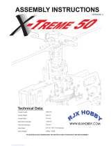
60/ 70
SE & Max 90
60/7060/70
60/7060/70
60/70 60/70 SE60/70 SE
60/70 SE60/70 SE
60/70 SE Max 90Max 90
Max 90Max 90
Max 90
MAIN BLADES MAIN BLADES
MAIN BLADES MAIN BLADES
MAIN BLADES 690mm690mm
690mm690mm
690mm 690mm690mm
690mm690mm
690mm 720mm720mm
720mm720mm
720mm
MAIN ROTOR SPAN MAIN ROTOR SPAN
MAIN ROTOR SPAN MAIN ROTOR SPAN
MAIN ROTOR SPAN 60.6 in60.6 in
60.6 in60.6 in
60.6 in 60.6 in60.6 in
60.6 in60.6 in
60.6 in 62.9 in62.9 in
62.9 in62.9 in
62.9 in
TAIL ROTOR SPAN TAIL ROTOR SPAN
TAIL ROTOR SPAN TAIL ROTOR SPAN
TAIL ROTOR SPAN 10.5 in10.5 in
10.5 in10.5 in
10.5 in 10.5 in10.5 in
10.5 in10.5 in
10.5 in 11.2 in11.2 in
11.2 in11.2 in
11.2 in
OVERALL LENGTH OVERALL LENGTH
OVERALL LENGTH OVERALL LENGTH
OVERALL LENGTH 54.5 in54.5 in
54.5 in54.5 in
54.5 in 54.5 in54.5 in
54.5 in54.5 in
54.5 in 55.7 in55.7 in
55.7 in55.7 in
55.7 in
HEIGHT HEIGHT
HEIGHT HEIGHT
HEIGHT 17.2 in17.2 in
17.2 in17.2 in
17.2 in 17.2 in17.2 in
17.2 in17.2 in
17.2 in 18.2 in18.2 in
18.2 in18.2 in
18.2 in
ENGINE ENGINE
ENGINE ENGINE
ENGINE 60 ~ 7060 ~ 70
60 ~ 7060 ~ 70
60 ~ 70 60 ~ 7060 ~ 70
60 ~ 7060 ~ 70
60 ~ 70 80 ~ 9080 ~ 90
80 ~ 9080 ~ 90
80 ~ 90
Century Helicopter Products
Designed and Developed in USA
1st Edition, Copyright March 2003. All rights reserved.
SPECIFICATIONS
Instruction
Manual

Building Instructions for the Predator series eCCPM helicopter kits.Building Instructions for the Predator series eCCPM helicopter kits.
Building Instructions for the Predator series eCCPM helicopter kits.Building Instructions for the Predator series eCCPM helicopter kits.
Building Instructions for the Predator series eCCPM helicopter kits.
IntroductionIntroduction
IntroductionIntroduction
Introduction
Congratulations on your purchase of Century Helicopter Product's newest RC helicopter
model. The Predator eCCPM is the most anticipated and long awaited Century model helicop-
ter. The attention is well deserved as the Predator will be unmatched in affordability, quality
and performance. Compared to other 60 class models, pilots will be elated to find the Predator
is built to please. This kit will exceed your expectations for precision control at an affordable
price.
It is recommended that the Predator be equipped with high quality radio equipment that has 8
to 9 channels and a minimum of 5 points on the throttle and pitch curves. Servos used should
be quality coreless, ball bearing and having a minimum torque rating of 70 oz/in. The gyro and
its servo should be quality with a servo speed of 0.11sec/600 or faster.
WarningWarning
WarningWarning
Warning
This radio controlled model is not a toy! It is a precision machine requiring proper assembly
and setup to avoid accidents. It is the responsibility of the owner to operate this product in a
safe manner as it can inflict serious injury otherwise. It is recommended that if you are doubt
of your abilities, seek assistance from experienced radio control modelers and associations. As
manufacturer, we assume no liability for the use of this product.
Pre-assembly InformationPre-assembly Information
Pre-assembly InformationPre-assembly Information
Pre-assembly Information
Upon opening the kit, all the major component parts are bagged by relationship to the differ-
ent sections of the helicopter. Various assemblies have been pre-assembled only requiring the
final assembly and installation onto the particular part, screws and nuts required for each step
are packaged in the same bag as the parts. Be careful when opening each bag as not to lose
any hardware. Care has been taken in filling and packing of each bag however mistakes do
happen, if there is a parts shortage or missing hardware please contact us at:
Century Helicopter Products
523 Sinclair Frontage Road
Milpitas, CA 95035
Tel: 1-408-942-9525
www.centuryheli.com

#HI6160
Rotor Head
Block
#HI6181
Head Damping
O-Rings
Press in the damping o-rings into the rotor head block.
Lubricate with light oil.
#CN2215A
Silver Head Button
Bond the threaded stud into the head button using permanent
locktight then apply more permanent locktight and bond into
the top of the rotor head block.
SE & Max
only
Assemble the seesaw part around the rotor head block. Bond
the bearing cups to the metal offset plates.
#HI3167B
Offset Plates
#HI3167F
Bearing Cups
#HI3167G
Tie Bars &
Spacers
#CNBB37
#CNBB48
#HI6167
Special Ball
Make sure that the steel ball is mounted on the left when on
the rotor head.
Steel Ball on
Left side.
The washout guide should be positioned against the rotor head
block, with the pins aligned parallel to the feathering spindle.
#HI6153
Washout
Guide
#HI6189
Bell Mixing
Arm
M3x15 Button
Head Screw
#HW6001
M3x6
Button Head
Screw
M3x4 Set
Screw
Press the M3x7 Flanged bearings into the seesaw capturing
one steel spacer in between. Attach to the blade grip with the
special shoulder bolt.
M3x18 Special
Shoulder Bolt
#HW6001
#CNBB37F
#CNLR1014
Short Ball
#CNLR1020
Medium Ball
1:1 3D
1:1.3 3D & Sport
1:1.6 Sport & FAI
Bell Mixer Ratios
3
21
34
56

#HI3176C Flybar
Control Yoke
Assemble each flybar control arm half before it is installed by
threading the double studded ball into the end of the tapered
end of the control arm.
Pushrod A
47mm (center
to center)
M3x12
Button Head
Screw
M4x6
Washer
M4x5 Set
Screw
#HW6180
Feathering Spindle
#HI6184
Main Blade Grip
#CNBB815T
M5x10 Socket
Screw & M5
Flat Washer
Slide three shims onto the feathering spindle, followed by the
blade grip assembly. Pitch arm is on leading edge. Grease and
install the thrust bearing and secure with the M5x10 socket
screw and washer using threadlock.
#CNBB816 M14 Thrust
Washer
Insert one ball bearing into each end of the main blade grip.
Slide the M14 Thrust Washer against the inside bearing.
Assemble the flybar, paddles and flybar yoke around the rotor
head and secure with the M4x5 set screws attached from the
top of the arms using threadlock.Adjust pushrod and attach to
from the seesaw to the medium ball on the adjustable side of
the bell mixer.
Bell mixer
assembly
Flybar Yoke
Assembly
#HW6173 Flybar
HI6179 20gr 3D Grey SE-Max
HI6179A 30gr Sport Black 60
Pushrod B
26mm (center to
center)
9.0:1 60 & SE 4
9.3:1 3
8.18:1 Max 1
8.45:1 Max 0
Gear Ratio Kit # Shims
M4x16 Socket
Screw
#HW6017
Engine Mount
Shims x 8
Before installing the engine, check the gear ratio to determine
the correct number of shims to install between the mounting
lugs on the engine and the engine mount.
Attach the seesaw assembly with one M3x18 special socket
screw threaded into the blade grip. Be careful not to over-
tighten the screw.
M3x18 Special Socket
Shoulder Screw
#HW6001
#CNLR1014
Short Ball #CNLR1020
Medium
Ball
#HI6181
Damping
Shims
7 8
9
1211
10
4

Install the engine into the mount using the correct number of
shims and ensure that the engine is centered in the mount. Use
locktight on the M4 socket screws.
Engine
centered in
engine
mount.
If a governor is planned to be installed, install the magnets
into the holes already molded into the bottom of the cooling
fan.
Hole for
govenor
magnet.
#HI6009
Cooling Fan
#HW6012
Fan Hub
The fan and hub are pre-assembled in the kit. The engine
collets will fit both O.S. Max and Y.S. crankshafts.
#HW6015
Lower Split
Collet #HW6015
Upper Split
Collet
Engine
Nut
M3x6 Flat
Head Socket
Screw x 4
Ensure that the split in the collet is positioned away from
slot for the Woodruff key. The lower collet is a tight fit to
the crankshaft. Use the engine nut to start the collet onto the
crankshaft, apply oil to collet.
Lower
Collet
Engine
Thrust
Washer
Position the fan assembly, apply oil to the collet and insert
the upper split collar and the original engine nut. Clean the
engine threads and apply locktight to the engine nut and
tighten in place.
Apply light grease to the Torrington bearing in the center of
the clutch shoe. Be sure that no grease contacts the
clutchbell.
#HW6011
Clutch Shoe
M3x6
Button Head
Screws x 2
Oil Collets
before
tightening
13 14
15
1817
16
5

Attach the clutch shoe with the M3 button socket bolts using
threadlock.
Clutch
Shoe
Fan
Assembly
Clean the clutchbell and inside of the bearing with alcohol.
Apply a small amount of permanent locktight around the top
15mm edge of the aluminum clutchbell where it will contact the
bearing. Ensure the bearing is against the clutchbell. Press
evenly and firmly as this is a very tight fit.
#HW6045
Lower
Short
Bearing Block
(top surface is
flat)
#HW6013 Clutch Bell Assembly 10T
#HW6013A Clutch Bell Assembly 11T
#HW6014 Replacement Clutch Lining
#HW6007
Clutch Shaft
Bearing Block
#HW6045
Lower
Long
Bearing
Block
M3x12 Socket Screw x 2
Clean the top of the clutchbell gear and inside of the upper
bearing with alcohol. Apply a small amount of permanent
locktight around the top edge of the clutch gear where it will
contact the bearing. Press the clutch shaft bearing block in
place. Attach the long bearing block with M3x12 socket
screws but do not tighten at this time.
#HW6042
Main Shaft Bearing Block
M3x8 Socket Screws x 8
26mm
Threaded Hex
Spacer
Attach the clutchbell and bearing block assembly, main shaft
bearing block and front hex threaded spacer with M3x8 socket
screws to the left upper side frame. Do not use locktight at this
time. Notice the countersunk hole below the bearing is on the
outside.
#HW6110
Upper left Side
Frame
Prepare the rear ccpm servo, attach the rubber servo tabs and
the eyelets from the top of the servo.
#HI3205
Servo
Mount
Tabs
Rubber servo tabs,
eyelets and screws
provided with radio.
Install the rear ccpm servo into the inside of the right side of
the upper side frames. Be careful, look for the countersunk
hole below the bearing is on the outside.
Servo
output
shaft to
rear of
helicopter.
19 20
22
6
21
23 24

Install the rear ccpm lever into the upper frames flush with
the bearing on the left side, having the mount extend out the
right side frame. Assemble the upper frames but do not use
locktight at this time.
#HI6031
CCPM
Cyclic
Bellcranks
#HI6110
Upper Side Frames
Left & Right
#HI6032
Rear CCPM Lever
#CNLR1014
Short Ball
#CNLR1020
Medium
Ball
M3x30
Socket Screw
#HW6000
Stepped
Standoff
26mm
Threaded
Spacer
The stepped standoff is positioned with the step against the
ball bearing in the ccpm bellcrank. Correct orientation has the
two symmetric steel ball facing outwards and the obtuse angle
towards the swashplate.
#CNBB37
Apply locktight to the threads on the inside standoff, insert
between the frames and attach the ccpm cyclic bellcranks
being careful to observe the correct direction. For 140
Degree ccpm setup, move bellcranks to forward holes.
M3x30
Socket Screw
#HW6000
120 Degree
CCPM Setup
Press the rear ccpm lever onto the mount that sticks out of the
right side of the upper frames with the steel ball downwards.
Secure with the M3 button head screw.
M3x10 Button
Head Screw
#CNLR1014
Short Ball
#HW6112A
Vertical Front
Frame
#HI6020
Cooling Fan
Mount
M3x8 Self Tap Screw (from behind)
8.45:1
only !
Attach the front cooling fan mount to the vertical front frame
inserting the M3 screw from the flat side of the frame. Note:
8.45:1 gear ratio requires the shroud mount hole to be modified.
#HW6127
Front Frame
Standoff Set
Ensure that the correct standoffs are used in the correct
locations. The 26mm threaded hex standoffs are not shown.
#HW6127A
Rear Frame
Standoff Set
X-Frame x 2
15mm Servo
Frames x 4
17mm Rear
Frames x 4
26mm Threaded
Standoffs x 2
26
29
30
7
28
27
25

M3x12
Socket
Screw
Attach two M3x12 Socket screws from the inside of the
battery tray at the forward holes and two M3x10 Socket
screws to the rear holes. Attach the vertical frame (note
flanges are rearward) to the battery tray with M3x8 screws.
M3x10
Socket Screw
#HW6112A Battery Tray &
Vertical Front Frame
M3x8
Socket
Screw &
Locknut
26mm
Threaded Hex
Standoff
Attach the servo frames, battery tray and upper frames
together using M3x25 Socket screws. Do not use locktight at
this time. These will be secured after the engine alignment is
complete.
M3x25
Socket
Screw
#HW6112
Servo Side
Frames
15mm
Standoffs x 4
Assemble the fuel tank fittings. Gently bend the vent line and
test until it reaches the top of the fuel tank. Order is larger
outside cap, rubber stopper, smaller inside cap. Test the
pickup line so it can move freely in the fuel tank.
#HI6138 Fuel Tank &
Fittings
M2.5x18
Self Tap
Screw
#HI6138 Fuel Tank & Fittings
Cable Tie
Upper tube for
vent line.
Side tube
for pickup.
After the fuel tank fittings are inserted, tighten the M2.5x18
self tap screw and attach the cable tie around the outside of
the stopper.
Install the rubber insulators to the frames. Install the left side
front lower frame over the M3 threaded studs on the battery
tray. Attach the shorter canopy standoff to the front stud and a
locknut to the rear stud. Attach the longer, rear canopy
standoff to the upper frames using M3x10 Button head screw
from the inside of the frames.
#HI6115 Front
Lower Frame
Rubber
Insulator
#HW6125
Front Short
Canopy
Mount
M3x8
Socket
Screw &
Locknut
M3
Locknut
Install fuel tank (only fits one way) and attach the other front
lower side frame. Similarly secure it to the vertical frame with
M3x8 socket screws and locknuts.
#HW6125
Rear Canopy
Mount w/
M3x8 Button
Head Screw
#HW6125
Front
Canopy
Mount
32
36
31
8
33
35
34

17mm
Standoff x 4
Attach the X Frame to the lower side frames first using M3x8
Socket screws and locknuts at the lower hole on a flat surface.
Attach to the upper frames with M3x25 Socket screws, apply
threadlock to the holes on the upper side frames.
#HW6115A
Rear Lower
Frames
#HW6117 Rear X Frame
X-Frame
Standoff x 2
26mm Threaded Standoff
M3x25
Socket
Screws
Before the main gear assembly can be inserted, make sure
that the M10x14x3.5 spacer is positioned on top of the lower
main shaft bearing. It will simply self align in the block.
Remember, do not locktight any bolts on the clutchbell or
starting shaft bearing blocks until the engine is installed.
#HW6054 Spacer
Slide the autohub for the slipper drive from the bottom of the
main gear. Attach with M3 button head screws and tightening
evenly. Insert the slipper cap assembly, capturing the o-ring
under the cap against the autohub.
#HW6001 Main
Shaft Pin & M4x4
Set Screws x 2
#M3x8 Button
Head Screw x 4
Thread the slipper cap onto the sleeve until the holes align
together. Insert two M4x4 set screws at 180 degrees apart and
tighten gently. Later when the main shaft pin is attached, these
can be removed and locktighted in place.
#HW6001
M4x4 Set
Screw x 2
#HI6058J
Slipper Sleeve
#HI6058K
Slipper Cap
#HI6058L
Slipper O-Ring
#HI6058P
Autohub -
Slipper
#HI6056 Main Gear
90T - Slipper Drive
#HI6058M
Autohub - Inner
Gear CT Drive
#HI6058B
Machined Inner
Gear 70T - CT
Drive
M3x6 Flat Head
Screws x 4
Install inner gear autohub from the bottom side the inner (tail)
gear using threadlock. Attach with M3 flat head screws and
tightening evenly. Note the autohub is pre-assembled.
M3x6 Flat Head
Screws x 4
Install outer gear autohub from the bottom side the outer main
gear using threadlock. Attach with M3 flat head screws and
tightening evenly. Overtigtening these screws could touch the
upper side frames.
#HI6058N
Autohub - Outer
Gear CT Drive
#HI6058C
Machined Outer
Gear 90T - CT Drive
#HI6058D
Machined Outer
Gear 93T - CT Drive
SE & Max
60/70 Kit
38
42
9
37
39
40
41

Insert the main gear assembly from the side and slide the
main shaft through the upper main shaft bearing block. Align
the M4 threaded hole with 3mm hole on the main shaft and
insert the pin.
#HW6001 Main Shaft M3 Pin
Main gear
assembly, slipper
or constant drive
type.
#HW6001 M4x4 Set Screw x 2
After the main shaft pin is started, press it in and start
threading the M4 set screws. Continue adjusting until the pin
is centered in the autohub assembly. Remove one at a time
and apply locktight. These do not need to torqued down.
Inspect the bottom collar, make sure the step in the collar is
towards the ball bearing. Press firmly on the main shaft until
the top threaded hole aligns with the holes in the bottom
collar. Apply locktight to the M3 Flat head screws.
#HW6054 Bottom Collar &
M3x6 Flat head screws x 2
Slipper
Main Gear
Install the main shaft thrust bearing (SE & Max only) and
0.25mm shim against the lower bearing followed by the bottom
collar. Make sure the step in the collar is away from the thrust
bearing. Apply locktight to the two M3 Flat head screws.
#HW6054 Bottom Collar &
M3x6 Flat head screws x 2
#CNBB1018T
& 0.25mm Shim
Constant
Drive
Main Gear
#HW6054
Mast Stopper
& M2.6x8
Socket screw
To set the upper mast stopper, press down firmly on the main
shaft and tighten the M2.6 Socket screw using locktight.
Install the starting shaft, pull up on the shaft and apply
locktight to the top of the shaft and position one of the set
screws on the flat spot.
#HW6002
Hex Coupler
& M4x4 Set
Screw x 2
Check once more that everything is ready on the engine.
Make sure that the carburetor has been seated properly and
the securing screw is tight.
#HW6005
Starting
Shaft Completed
engine
assembly.
#HW6011
Clutch Shoe
#HW6009
Cooling Fan
#HW6053 Main Shaft
44
45
48
10
43
46
47

#HW6017
M4x10 Socket
Screws &
M4x12 Flat
washers x 6
Slide the engine assembly in place and install the M4 Socket
bolts and washers. Do not locktight these and leave these
loose until the clutch is aligned to the clutchbell. Some fore -
aft adjustment is possible. Install the M3 screws for the
shroud and leave loose for adjustment later.
Paper strip
to set gear
mesh.
Cut a strip of paper 1/2” (12mm) wide to set the gear mesh
between the clutch bell and the main gear. The paper should
run through the gears without tearing. After the M4 engine
screws are tight, the M3x12 screws are tighted last.
Remove and locktight
M3x8 Socket screw.
M3x8 Self Tap
Screw x 2
Sighting the bottom of the clutch bell, adjust until the
clutch is parallel to the clutchbell in both the left/right and
front/back directions. Fore-Aft is adjusted by the M3 screws at
the top of the servo tray. Once satisfied, carefully remove and
locktight all the M3 and M4 bolts. Insert the M2.6 screw to
capture the front of the cooling shroud.
Parallel
M3 Socket Screws
M4 Socket
Screws
By loosening the M3x8 and M2.6 self tap screws that hold
the cooling fan shroud to the frames, the shroud can be
adjusted until it does not to touch the cooling fan.
M3x12
Socket
Screws x 2
Install both left and right front ccpm servos to the servo
frames. Secure using the servo tabs held by pliers from
behind. Install the short steel ball to the underside of the servo
arm at a 20mm radius with M2 hex nut on top. Ensure the 90
degree angle on bellcrank to swashplate pushrod at midstick.
Pushrod D 120mm
(center to center) x 4
Left front
ccpm
servo
900
Parallel
D
#HI6020
Cooling Fan Shroud
Match the cooling fan shroud together and secure with M2.6
screws. Do not install the frontmost screw at this time.
#HI6020
M2.6x10 Self Tap
Screws x 2
M2.6x10
Screw
Gap
Clutch must
be parallel
fore - aft and
side to side.
49
50
52
11
51
53
54

Install throttle servo to the right side frames. Attach the short
ball with M2 thread to the carburetor lever arm with M2 nut
and the short steel ball to the top side of the servo arm at
13.5mm. Ensure the 90 degree angle from the pushrod to the
servo and carburetor arm for linear setup at midstick.
Parallel
Parallel
Pushrod E 100mm
(center to center)
Pushrod F
116mm (center
to center)
#CNLR1018 Ultra
Short Steel Ball
Optional metal
servo arms
shown.
The double bearing swashplate requires no maintenance. If a
steel ball needs changing, insert the 2.5 hex key through one
of the extra holes in the outside ring. Two medium ball on the
inside race.
#HI6146 Swashplate
Assembly
#CNLR1014 Short
Steel Ball x 5
#CNLR1019 Long
Steel Ball x 2
Pushrod G 56.5mm
(center to center) x 2
Parallel
Install the swashplate on the main shaft and connect to the
rear and front ccpm pushrods. Trim the radio to level the
swashplate, set to 90 degrees to the main shaft.
90
0
#HI3152C Washout
Assembly #HI3152A
Radius Link
& Pin
M3x16
Button Head
Screw x 2
#CNBB37 x 4
#CNLR1020
Medium Steel
Ball x 2
The washout unit comes assembled. Slide onto the main shaft
and ensure that the screw is on the left side of the main shaft.
M3x5x0.5
Micro Washer
x 2
Slide the washout guide and align the washout pins with the
washout guide. Attach the rotor head with M4 socket head
cap screw and M4 locknut. Insert the M3 set screws and
position the guide with the screws aligned to the slot in the
head block.
Pushrod A
47mm (center
to center) x 2
M4x22 Shoulder
Socket Screw &
M4 Locknut
M3x4 Set
Screw x 2
Pushrod C
102mm (center
to center) x 2
Attach pushrod C from the long ball on the inside race of the
swashplate to the single ball (non adjustable) on the bell-
hiller mixing arms. These pushrod lengths are starting points,
adjustment is necessary for the particular style of flying.
#HW6192A
Lower Linkage
Set (8 rods)
#HI6145 Ball Link Set
(26 long & 4 short)
Pushrod B
26mm (center
to center) x 2
M3x5x3 Steel
Spacer x 2
56
58
12
55
57
59 60

The main rotor grips will accept rotor blades that have a root
thickness that is from 12mm to 18mm and have a 5mm hole.
Carbon Rotortech and wooden Aerotech blades are designed
for 5mm blades bolts.
#HW6001 M5x35
Shoulder Socket
Screw x 2 & M5
Locknut x 2
Assemble the landing skids onto the struts, note the correct
direction is to have the struts sweep forward. Position the rear
strut at approximately 37mm from the end and secure the skid
with the M3 set screw. Leave the front loose for now.
#HI6122 Landing
Struts x 2
60/70 & SE
#HW6123 10mm
Landing Skids x 2
~ 1 1/2”
[37mm]
M3x4 Set
Screws x 4
Attach the landing gear frame to the mechanics with M3x8
socket screws and locknuts. Attach the landing gear with
M3x20 socket screws, M3x10 flat washers (against struts)
and locknuts, sliding the front skids into final position.
Secure the M3 set screws.
M3x20
Socket
Screws x 4
& M3x10
Flat Washers
M3x8 Socket Screws x 4
& M3 Locknuts x 8
Note
locknut
on top.
#HW6117
Landing
Gear Frame #HI6122A Landing
Struts - Carbon x 2
#HW6123A 12mm
Landing Skids x 2
60/70 & SE
Max 90
Attach the landing gear frame to the mechanics with M3x8
socket screws and locknuts. Attach the landing gear with
M3x20 socket screws, M3x10 flat washers (against struts),
M3x9x4 spacers and M3 locknuts, sliding the front skids into
final position. Mark, scuff and bond the skids to the structs
with JB Weld.
The front tail transmission is assembled. Open and apply
locktight to the back edge of the bevel gear for added security.
#HI6060 Front Tail
Transmission
#HI6154
Torque Tube
Drive Coupler
& M4x5 Set
Screw
M5x10 Collar &
M3x5 Set Screw
#CNBB511 x 2
#HW3057 Tail
Bevel Gear &
M3x5 Set Screw
M5x7x2
Spacer x 4
#HW6059 Tail Transmission
Drive Shaft 26mm Threaded
Hex Spacers x 3
#HW6062 Tailboom 795mm 60/70 & SE
#HW6062A Tailboom 825mm Max 90
#HW6063 Torque Drive Shaft 60/70 & SE
#HW6063A Torque Drive Shaft Max 90
Insert the 26mm hex spacers into the transmission half.
#HW6192 Upper
Linkage Set (6 rods)
#HI6145 Ball Link Set
(26 long & 4 short)
61
13
62
64
63
65 66

Looking down on the two tail gears notice that the black gear
has teeth that are in the opposite direction to the silver gear.
Make sure the black gear is mounted to the tail output shaft.
#HW6075 Tail
Gear Set
Black Gear - Tail Output Shaft
Counter-Clockwise Teeth Silver Gear - Tail
Input Shaft
Clockwise Teeth
Align the hole in the black gear over the hole in the end of tail
output shaft and secure with the M3 set screw using locktight.
Slide the spacer tube against the gear.
#HW6073 Tail
Output Shaft
#HW6074 Spacer Tube -
Tail Output Shaft
M3x4 Set Screw
Recessed hole.
Align the hole in the silver gear over the hole in the end of the
tail input shaft and secure with the M3 set screw. Slide two
M5x13 bearings and install temporarily into one half of the
gearbox (positioning the bearings) and secure the torque
coupler with M4 set screw over the flat spot using threadlock.
#CNBB513 x 2
#HI6154 Torque Tube
Coupler & M4x5 Set
Screw
#HW6070 Tail Input
Shaft
Black
Gear
Silver
Gear
M3x4 Set Screw
Press one M5x13 bearing into the right hand side (with mount
for tail pitch lever) of the tail gearbox. Position the tail output
shaft and input shaft into the gearbox half. Adjust torque
fitting if necessary. Pack gears with quality grease.
#HI6078 Tail
Gearbox Half
#CNBB513
Insert the torque drive shaft using a little oil on the o-rings as
it is pressed into the tailboom (press towards the bearing) and
align the tailboom end to the molded key in the tail gearbox.
Close the gearbox with the M3 socket screws and locknuts.
#CNBB511
Use high performance
grease for metal gears.
#HI6078 Tail
Gearbox
M3x20 Socket Screw
(middle bottom)
M3x15
Socket Screw
(middle top)
M3x10 Socket
Screw
M3 Locknut
x 3 #HI3087A
Pitch Slider
Set
#HI6102 Tail
Pitch Lever Set
#HI3089 Tail Pitch
Ball Links x 2
#CNLR1014
Short Steel
Ball
#HW6001
M3x15 Shoulder
Screw
#CNBB37F
x 2
M3x5 Spacer
#CNLR1003
M3x5x0.5 Micro
Washer
Slide the tail pitch slider set onto the tail output shaft and
insert the M3 shoulder screw from the bottom of the pitch
lever with the micro washer between the lever and the mount
on the gearbox and tighten in place.
68
72
70
14
67
69
71

Press the M4 bearing into the end, slide the M3 thrust
bearing (in correct order), micro washer, M3 bearing and
locknut from inside the grip. Use locktight on the locknut.
#HW3098A Steel
Tail Rotor Hub
#CNBB410 x 2
#HI3096A Tail
Grips x 2
#CNLR1013 x 2 Short Steel Ball
#CNBB49T x 2
#CNBB0930
x 2
#CNLR1003 M3x5x0.5
Micro Washer
M3 Locknut x 2
Insert tail rotor grip assembly onto the tail output shaft,
aligning the set screw over the indent in the shaft using
locktight. Attach the tail pitch ball links to the balls, the steel
ball is on the leading edge of the blades.
M3x4 Set Screw
Tail rotor
assembly
Tail rotor blades are installed with the leading edge rotating
upwards into the downwash of the main blades. Looking at
the left side of the Predator, the blades turn clockwise with
the steel ball on the leading edge.
#CN260956 Rotortech 95mm Tail Blades - SE
#CN261056 Rotortech 105mm Tail Blades - Max 90
#HI6099 Tail Rotor
Blades - 60/70
#HW6001 M3x18 Shoulder
Socket Screw x 2
M3x10x1.5
Spacers x 4
M3 Locknut x 2
The carbon tail blades will not fit the tail rotor grips without
trimming the ends. Attach the two blades together and grind
3-4mm off the end of the blades as shown.
Bolt both blades
together.
Grind 3-4mm
off end.
Install the tail rotor blades to the tail rotor grips with the M3
shoulder socket cap screws, M3 spacers on both sides the the
blades and secured with M3 locknuts, fitted into the molded
recess on the tail blade grips.
Completed tail
gearbox assembly.
Locknuts
face
outside.
Insert the front of the tail boom into the front tail transmis-
sion half and close the transmission. Secure with M3 socket
screws locknuts. Attach the tail boom assembly to the
mechanics with M3x8 screws first then the Flat head screws.
Attach first, then remove and locktight all the screws.
M3x10 Flat Head
Screw x 2
M3x8 Socket Screw x 4
M3x12 Socket
Screw x 4
& M3 Lock-
nut x 4
#CNLR1014
Short Steel
Ball
74
15
73
75
76
77 78

Insert the M2 threaded rod 10mm into the grey ball link.
Slide the end cap over the carbon tube and make a mark,
remove and sand the carbon up to this mark for better
adhesion. Using JB Weld or Epoxy bond in place. Only
complete one end at this time. Thread the ball link into the
end cap until it stops using threadlock.
#HW6065 Tail
Pushrod Set
#CNLR1000S
Insert 10mm into
grey ball link.
End Cap
Only
complete
one end
now!
SE & Max 90 only.
Insert and mark each end of the carbon struts where the strut
fittings will overlap. Remove and sand down each carbon
end until they slide easily into the fittings. Scratch inside the
fittings also. Using JB Weld or Epoxy, bond the fittings in
place. Make sure each strut has the fittings 900 degrees to
each other.
#HW6202A Carbon
Support Struts x 2
#HI6080 Tail
Servo Mount
Set
Install the rudder servo into the tail rudder servo mounts
using M2.5 self tapping screws inserted through the top of
the servo grommets into the vertical mounts.
M2.5x12 Self
Tapping
Screw x 4
Wrap the tail mount liners around the tail boom and trim if
necessary. Install the rudder servo mount assembly onto the
tail boom, over the liners and secure using the M2.5 socket
screws. Leave these loose until after the tail pushrod has
been attached. Attach the rudder servo horn, positioning the
steel ball at 12-14mm from the servo center.
M2.5x12
Socket
Screw x 2
M2.5x12 Socket
Screw x 2
60/70 only.
#HI6067 Tail Fin Set -
Horizontal & Vertical
Install the decals for the fins at this time.
#HI6080 Tail
Mount Liner x 2
The Aluminum support struts are ready for installation.
#HW6202
Tail Support
Strut Set -
Aluminum
60/70 only.
79 80
81
16
83 84
82

Attach the struts (aluminum or carbon) to the main mechanics
using M3 socket screws, M3x9x3 plastic spacer on the outside
and secure with M3 locknuts on the inside of the frames.
M3x12 Socket Screws x 2 &
M3 Locknuts x 2
M3x9x3
Spacer x 2
Slide the bottom fin mount (taller side of angled ends
towards mechanics) over the M3 screws and insert the
carbon tail struts and secure with M3 locknuts.
#M3x40 Socket Screws x 2
& M3 Locknuts x 2
Angled
bottom fin
mount
#HI6067A Carbon
Horizontal Fin #HI6068 Tail Fin
Mount Set
M3x40 Socket
Screws x 2
SE & Max 90
only.
Insert the M3 socket screws through the top of the carbon
fin and through the top tail fin mount (straight ends).
Notice that the bottom fin mount is angled for comparison.
#HI6067
Horizontal
Fin
#HI6068 Tail Fin
Mount Set
M3x35 Socket
Screws x 2
Insert the M3 socket screws through the top of the plastic fin
and through the top tail fin mount (straight ends). Notice that
the bottom fin mount is angled for comparison.
60/70 only.
M3x35 Socket
Screws x 2
Insert the M3 socket screws through the front holes in the
plastic vertical fin and through the vertical fin mount.
#HI6067
Vertical Fin
Slide the bottom fin mount (taller side of angled ends
towards the mechanics) over the M3 screws and insert the
aluminum tail struts and secure with M3 locknuts.
#M3x35 Socket Screws x 2
& M3 Locknuts x 2
Angled
bottom fin
mount
85 86
90
88
17
89
87

Assemble the support bridge with M3 hardware. Press each
side onto the support strut and secure with the cable tie
wraps provided.
Cable Tie x 4
SE & Max 90
only.
#HI6082 Tail
Support Bridge M3x15 Socket
Screw, M3x8
Flat Washer x 2
& M3 Locknut
Slide the two tail pushrod clamps over the unfinished end of
the tail pushrod and attach to the tail boom. Press the ball
link onto the steel ball on the tail pitch bellcrank. Position
the one guide infront of the horizontal fin and one half way
between the fin and the mechanics bringing the pushrod to
the right side of the helicopter.
Tail pushrod
with one end
assembled.
#HI6106
Adjustable Tail
Guides
Remove the pushrod from the servo and slide through the
entire range of movement. Continue adjusting the guides
until the pushrod moves very smooth and then secure the tail
guides with the cable ties.
Assemble the other pushrod end cap and ball link to mark
and cut the tail pushrod to match the steel ball on the servo.
Bond the end cap in place and fine tune the position by
moving the rudder servo mount and then tighten in place.
Cut, sand and bond the
tail pushrod end cap.
Tighten after final
positioning.
Engage the rear M3 socket screws through the mounts on the
tail gear box and attach the forward gear box mount captur-
ing the tail boom and secure in place with M3 locknuts.
#HI6068 Forward
Gearbox Mount
M3 Locknut x 4 Carbon or Plastic
Vertical Fin
91 92
93
9695
94
18
Insert the M3 socket screw through the vertical fin and
through the first gearbox mount.
#HI6067A Carbon
Vertical Fin
#HI6067 Plastic
Vertical Fin
#HI6068 Front
Gearbox Mount
M3x35 Socket
Screws x 2
M3x25 Socket
Screws x 2

#HI6133
Windshield
Leave the protective coating in place until after it is drilled
for mounting screws. Rough cut the windshield leaving 3mm
[1/8”] then carefully cut out the windshield following the
line molded into the winshield.
Position the windshield and tape in place. Mark and drill
pilot holes around the windshield edge, centered through the
matching recess of the canopy.
#HI6130 Fiberglass
Gelcoat Canopy
Drill 8-9 holes.
Bond the wood inside mounts into the inside of the canopy
with Epoxy. Center each block over the holes with the top
edge flush to the canopy edge. Once cured, drill the final
hole size for the screws.
#HW6125
Wood inside
mounts
Flush to canopy
edge.
Clean the canopy. Trim the decals from the sheet and apply
to the side of the canopy before the lower grommet is
installed. Cut through the decal and install the lower grom-
met through the canopy.
#HI6131 Decal
Sheet
#HW6125
Rubber
Grommets x 4
Install lower
grommet after the
decal is applied.
M3x6 Self Tap
Screws x 10
Attach the windshield with the M3 self tapping screws
being careful not to overtighten them.
After the canopy is finished, the wooden blocks can be
painted white to match the canopy. The rubber grommets
should be reinforced using “Goop” adhesive or similar.
Reinforce the
rubber gromments
on the inside using
“Goop” adhesive.
60/70 SE &
Max 90 Decal Locations
1. 8. Lower cheek of canopy.
2. 7. Middle, below windshield.
3. 6. From edge below rear grommet
4. 10. Horizontal Fin (top & bottom on 60/70).
5. 9. Vertical Fin (above & below on 60/70).
97 98
102
100
19
99
101

HI6009 COOLING FAN
HI6020 COOLING FAN SHROUD SET
HI6031 CCPM CYCLIC BELLCRANKS
HI6032 CCPM ELEVATOR LEVER SET
HI6056 MAIN GEAR - 90T
HI6058B MACHINED TAIL GEAR - 70T CT DRIVE
HI6058C MACHINED MAIN GEAR - 90T CT DRIVE
HI6058D MACHINED MAIN GEAR - 93T CT DRIVE
HI6058F CONSTANT TAIL DRIVE ASSEMBLY - 90T
HI6058G CONSTANT TAIL DRIVE ASSEMBLY - 93T
HI6058J SLIPPER SLEEVE
HI6058K SLIPPER CAP
HI6058L SLIPPER O-RINGS (2)
HI6058M INNER TAIL GEAR AUTO HUB - CT DRIVE
HI6058N OUTER MAIN GEAR AUTO HUB W/T.B. - CT DRIVE
HI6058P SLIPPER AUTOROTATION HUB W/T.B.
HI6060 FRONT TAIL TRANSMISSION (L&R)
HI6067 TAIL FIN SET - PLASTIC
HI6067A TAIL FIN SET - CARBON
HI6068 TAIL FIN MOUNT SET
HI6078 TAIL GEARBOX (L&R)
HI6080 TAIL BOOM SERVO MOUNT SET
HI6082 TAIL STRUT SUPPORT BRIDGE SET
HI3087A TAIL PITCH SLIDER SET
HI3089 TAIL PITCH BALL LINKS
HI3096A TAIL BLADE GRIP SET
HI6099 TAIL ROTOR BLADES - PLASTIC (2)
HI6102 TAIL PITCH LEVER SET
HI6106 TAIL PUSHROD GUIDES - ADJUSTABLE SLOT
HI6122 LANDING STRUTS - PLASTIC
HI6122A LANDING STRUTS - CARBON
HI6130 FIBERGLASS CANOPY ONLY
HI6131 PREDATOR & MAX DECAL
HI6132 INSTRUCTION MANUAL - 60, SE & MAX
HI6133 WINDSHIELD ONLY
HI6138 FUEL TANK w/FUEL FITTINGS & ISOLATORS
HI6145 BALL LINK SET (26 LONG, 4 SHORT)
HI3152A RADIUS LINK W/PIN (2)
HI3152C WASHOUT SET - 10MM
HI6153 WASHOUT GUIDE
HI6154 TORQUE TUBE DRIVE COUPLER
HI6160 ROTOR HEAD YOKE
HI6167 SPECIAL BALL SET
HI3167B SEESAW OFFSET PLATES (2)
HI3167F BEARING CUPS & SPACERS (2) - M8
HI3167G SEESAW TIE BAR & SPACERS (2)
HI3176C SYMMETRICAL FLYBAR YOKE SET
HI6179 FLYBAR PADDLES - 20 GRAM 3D
HI6179A FLYBAR PADDLES - 30 GRAM SPORT
HI6181 HEAD DAMPING O-RINGS (6)
HI6184 MAIN ROTOR BLADE GRIPS (2)
HI6189 METAL BELL MIXER ARM SET
HI3205 SERVO MOUNTING TABS (10)
HW6000 HARDWARE PACK
HW6001 HEAD BOLT & WASHER SET
HW6002 HEX ADAPTER
HW6005 STARTER SHAFT
HW6007 START SHAFT BEARING BLOCK w/BB
HW6011 CLUTCH SHOE
HW6012 COOLING FAN HUB
HW6013 CLUTCH BELL ASSEMBLY - 10T
HW6013A CLUTCH BELL ASSEMBLY - 11T
HW6014 CLUTCH LINING
HW6015 SPLIT COLLET SET - OS/YS
Predator 60, SE & Max Replacement Parts
HW6017 ENGINE MOUNT - OS/YS w/SHIMS
HW6042 MAIN SHAFT BEARING BLOCK w/BEARING
HW6045 LOWER BEARING BLOCK ASSEMBLY w/BB
HW6053 MAIN SHAFT
HW6054 MAST STOPPER w/BOTTOM COLLAR
HW3057 TAIL TRANSMISSION BEVEL GEAR
HW6059 TAIL TRANSMISSION DRIVE SHAFT
HW6062 TAIL BOOM - 60/70
HW6062A TAIL BOOM - MAX 90
HW6063 TAIL DRIVE SHAFT SET - 60/70
HW6063A TAIL DRIVE SHAFT SET - MAX 90
HW6065 TAIL PITCH CONTROL ROD SET - CARBON
HW6070 TAIL GEARBOX INPUT SHAFT
HW6073 TAIL GEARBOX OUTPUT SHAFT
HW6074 SPACER TUBE - TAIL OUTPUT SHAFT
HW6075 TAIL GEAR SET
HW3098A STEEL TAIL ROTOR HUB
HW6110 UPPER SIDE FRAME - L&R
HW6112 SERVO SIDE FRAMES (2)
HW6112A VERTICAL FRAME & BATTERY TRAY
HW6115 FRONT LOWER FRAMES - L&R
HW6115A REAR LOWER FRAME - L&R
HW6117 LANDING GEAR FRAME & REAR X FRAME
HW6123 LANDING SKIDS - ALUMINUM
HW6123A LANDING SKIDS - CARBON
HW6125 CANOPY MOUNTS & GROMMET SET
HW6127 FRONT FRAME STANDOFF SET
HW6127A REAR FRAME STANDOFF SET
HW6146 CCPM SWASHPLATE 120-140 DEGREE
HW6173 FLYBAR
HW6180 FEATHERING SHAFT
HW6192 UPPER LINKAGE SET (6 RODS)
HW6192A LOWER LINKAGE SET (8 RODS)
HW6202 TAIL BOOM SUPPORT STRUTS (2)
HW6202A TAIL BOOM SUPPORT STRUTS - CARBON
CN2215A HEAD BUTTON - SILVER
CN2341 AEROTECH 690mm H/P ARF MAIN BLADES
CN267001 ROTORTECH 700mm 3D CARBON BLADES
CN267201 ROTORTECH 720mm 3D CARBON BLADES
CN260956 ROTORTECH TAIL BLADES 95mm
CN261056 ROTORTECH TAIL BLADES 105mm
CNBB37 Bearing - seesaw, washout, cyclic & bell mixers
CNBB37F Bearing - tail pitch lever
CNBB0930 Bearings - tail grip (2)
CNBB48 Bearing - flybar
CNBB49T Bearing - tail grip thrust
CNBB410 Bearing - tail grip
CNBB511 Bearing - start shaft, tail trans & output
CNBB513 Bearing - tail trans, tail input & output
CNBB610 Bearing - tail pitch plate
CNBB812F Bearing - elevator lever
CNBB815T Bearing - main grip thrust
CNBB816 Bearing - main grips, tail drive support
CNBB1018T Bearing - main shaft thrust
CNBB1019 Bearing - main shaft
CNLR1000S BALL LINK 2MM Rudder Pushrod (10)
CNLR1013 SHORT STEEL BALL M2 (2)
CNLR1014 SHORT STEEL BALL M3 (2)
CNLR1018 ULTRA SHORT STEEL BALL M2 (2)
CNLR1019 LONG STEEL BALL M3 (2)
CNLR1020 MEDIUM STEEL BALL M3 (2)
20
/