Whirlpool AKR 926 IX Program Chart

Category
Cooker hoods
Type
Program Chart

This manual is also suitable for

AKR 926-927
5019 100 75185/A
INSTALLATIONSANGABEN
Mindestabstand zur Kochfläche: 65 cm (Elektroplatten), 75 cm (Gas-, Öl-, Kohlekochmulde).
Bei der Installation die Nummerierung befolgen (1
Ö
2
Ö
3
Ö
.....). Das Auslassrohr und die
Befestigungsschellen (15) werden nicht mitgeliefert und müssen gesondert erworben
werden. Überprüfen Sie, ob Sie den Kamin von unten an der Dunstabzugshaube (16)
festgeschraubt haben und ob diese korrekt an der Wand (10) befestigt wurde. Das Gerät darf
erst nach erfolgter Installation an die Stromversorgung angeschlossen werden. Der Stecker
der Dunstabzugshaube muss mit einer normgerechten und gut zugänglichen Steckdose
verbunden werden. Wenn die Dunstabzugshaube nicht mit einem Stecker versehen ist
(direkter Netzanschluss), muss ein zweipoliger, normgerechter, (gut zugänglicher) Schalter
eingebaut werden, dessen Kontakte einen Abstand von mindestens 3 mm aufweisen.
INSTALLATION SHEET
Minimum height above cooker: 65 cm (electric cookers), 75 cm (gas, gas oil or coal cookers).
To install follow points (1
Ö
2
Ö
3
Ö
.....). The exhaust pipe and fixing clamps (15) are not
provided and should be bought separately. Ensure that the hood is fitted to the wall (10) and
the bottom flue to the hood (16). Do not connect the appliance to the electrical power supply
until installation is completed. The power plug of the hood must be connected to a socket
that complies with current regulations, located in an easily accessible point. If the hood is
not fitted with a plug (direct connection to the power supply), fit a two-pole switch in
compliance with regulations, with minimum break distance between contacts of 3 mm
(easily accessible).
FICHE D'INSTALLATION
Distance minimale par rapport à la cuisinière : 65 cm (cuisinière électrique), 75 cm
(cuisinière à gaz, mazout ou charbon). Pour le montage, suivez la numérotation
(1
Ö
2
Ö
3
Ö
.....). Le tuyau d'évacuation et les colliers de fixation (15) ne sont pas fournis avec
l'appareil et doivent être achetés à part. Assurez-vous d'avoir fixé la hotte à la paroi (10) et la
cheminée inférieure à la hotte (16). Ne branchez pas l'appareil tant que l'installation n'est pas
terminée. La fiche de la hotte doit être branchée dans une prise conforme aux normes en
vigueur, placée dans un endroit accessible. Si la hotte est dépourvue de fiche branchement
direct sur le réseau, appliquez un interrupteur bipolaire conforme aux normes ayant une
ouverture minimale de 3 mm entre les contacts (accessible).
INSTALLATIEKAART
Minimumafstand tot het kooktoestel: 65 cm (elektrische kooktoestellen), 75 cm
(kooktoestellen op gas, olie of kolen). Volg voor de montage de nummering (1
Ö
2
Ö
3
Ö
.....).
De afvoerleiding en de bevestigingsklemmen (15) worden niet bijgeleverd en dienen
aangeschaft te worden. Controleer of de wasemkap aan de muur (10) en de onderste schouw
aan de wasemkap (16) is vastgezet. Geef het apparaat geen stroom totdat de installatie
geheel voltooid is. De stekker van de kap moet op een goed toegankelijk stopcontact
aangesloten worden dat aan de geldende veiligheidsvoorschriften voldoet. In het geval dat
de kap geen stekker heeft (directe aansluiting op het elektriciteitsnet) dient u een tweepolige
schakelaar te gebruiken met een afstand tussen de contacten van minstens 3 mm, die aan
de geldende voorschriften voldoet.
D
GB
F
NL
75185A.fm5 Page 1 Monday, November 6, 2000 3:57 PM
5019 100 75185/A
AKR 926-927
FICHA DE INSTALACIÒN
Distancia mínima desde los fuegos: 65 cm (fuegos eléctricos), 75 cm (fuegos de gas,
gasóleo o carbón). Para el montaje, siga la numeración (1
Ö
2
Ö
3
Ö
.....). El tubo de salida y las
abrazaderas de fijación (15) no se suministran con la campana y deben comprarse aparte.
Asegúrese de haber fijado la campana a la pared (10) y la chimenea inferior a la campana
(16). No conecte el aparato a la corriente eléctrica hasta que la instalación esté
completamente finalizada. La clavija eléctrica de la campana debe conectarse a una toma de
corriente conforme a las normas vigentes y situada en un lugar accesible. Si la campana
carece de clavija (conexión directa a la red), se debe instalar un interruptor bipolar
homologado con una distancia de apertura de los contactos no inferior a 3 mm y situado en
una posición accesible.
FICHA DE INSTALAÇÃO
Distância mínima dos fogões: 65 cm (fogões eléctricos), 75 cm (fogões a gás, óleo ou
carbono). Para a montagem siga a numeração (1
Ö
2
Ö
3
Ö
.....). O tubo de descarga e tiras de
fixação (15) não são fornecidos com o aparelho pelo que devem ser adquiridos. Certifique-
se de ter fixado bem o exaustor à parede (10) e a chaminé inferior ao exaustor (16). Não ligue
o aparelho à corrente eléctrica até a instalação estar concluída. A ficha eléctrica do exaustor
deve estar ligada a uma tomada em conformidade com as normas em vigor, e colocada num
sítio acessível. Se o exaustor não estiver equipado com uma ficha (ligação directa com a
rede eléctrica) aplique um interruptor bipolar segundo as normas com uma distância dos
contactos à abertura não inferior a 3 mm (acessível).
SCHEDA INSTALLAZIONE
Distanza minima dai fuochi: 65 cm (fuochi elettrici), 75 cm (fuochi a gas, gasolio o carbone).
Per il montaggio seguire la numerazione (1
Ö
2
Ö
3
Ö
.....). Tubo di scarico e fascette di
fissaggio (15) non sono fornite e vanno acquistate. Assicurarsi di aver fissato la cappa alla
parete (10) e il camino inferiore alla cappa (16). Non dare corrente all’apparecchio finché
l’installazione non è totalmente completata. La spina elettrica della cappa deve essere
allacciata ad una presa conforme alle norme vigenti posta in zona accessibile. Se la cappa è
sprovvista di spina (collegamento diretto alla rete) applicare un interruttore bipolare a norme
con una distanza dei contatti in apertura non inferiore a 3 mm (accessibile).
ùüùü+ùùùþ
ü$12.)12.1.)2"0120" FP02!"0120" FP0120".0! #
02!0. #0! # +.2221.  #1202.!1
Ö
Ö
Ö

1&."..&".2. !.120!&1"/0/.202.02. !! 32!.
.!0.. 2 *$&!12ú0.&020.2120!&12 #. !! 32!.12
2 $ .2"2&./."12. !! 32!.2! 3 / 2020002!)
!0*.21#10#!2  !&12"0.212.1"02!)3"2 #
. !! 32!.!0.1#/0010!.102 #1$* 2 ". 1 *
2  0210! 101 10ü . !! 32!."/0/.203".0#0."
1*/0102 /2# 2  02120./ )/.)2102&. 1+0
0$12  .02.*2&0.3+ PP10! 101 10
E
P
I
GR
75185A.fm5 Page 2 Monday, November 6, 2000 3:57 PM
AKR 926-927
5019 100 75185/A
Nur in der Umluftversion
For Filter Version only
Uniquement pour la Version
filtrante
Uitsluitend voor de filterversie
Sólo para el modelo con filtros
Apenas para Versão filtrante
Solo per Versione filtrante
) . 2
..!!)31"
75185A.fm5 Page 3 Monday, November 6, 2000 3:57 PM
5019 100 75185/A
AKR 926-927
1
4
2
2
3
1.
Control panel
2.
Grease filters
3.
Lighting unit
4.
Telescopic flue
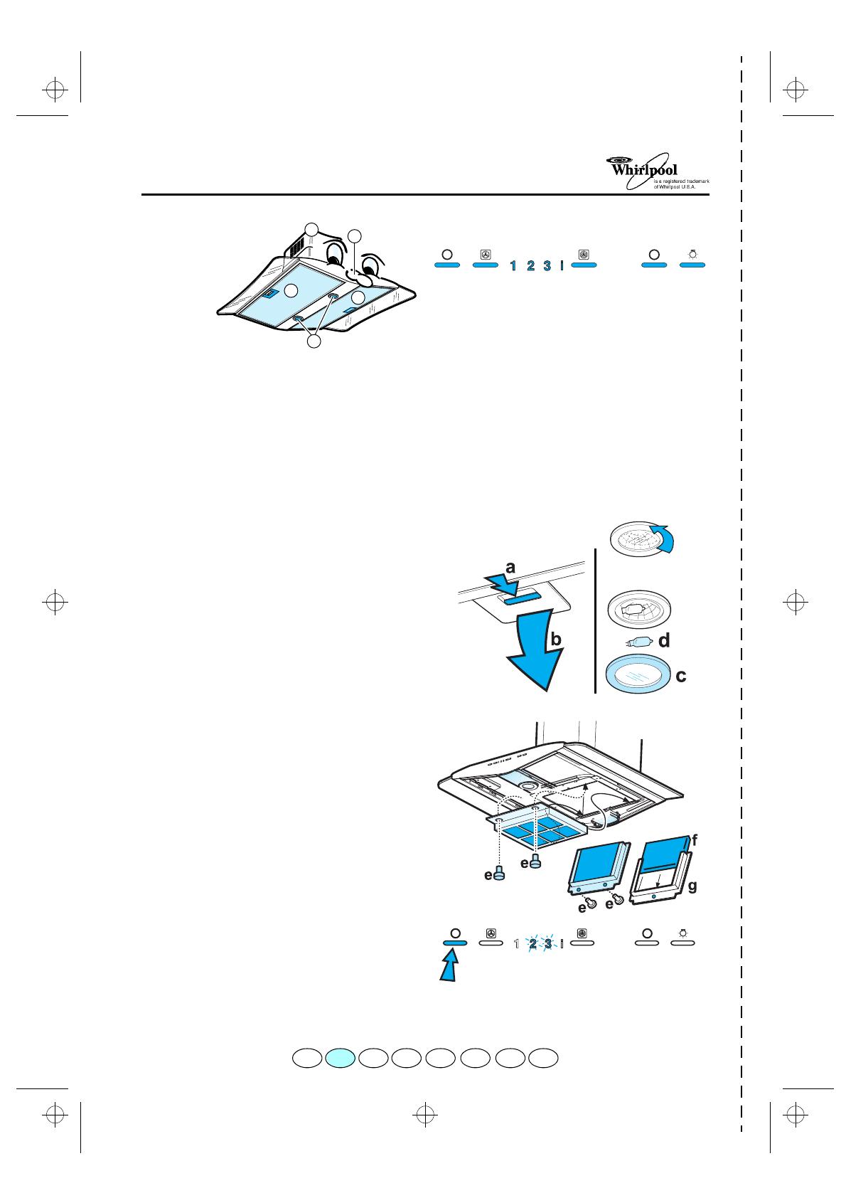
Cleaning the grease filter
Wash the grease filter once a month, or whenever
the grease filter saturation indicator flashes
(Extraction speed indicator
2
).
1.
Unplug the appliance or disconnect the mains
power supply.
2.
Remove the grease filters: push the handles
towards the lighting unit, then downwards
(a,b - Fig. 1)
.
3.
After washing the metal grease filter, remount in
reverse order ensuring that the entire extraction
surface is covered.
Replacing bulbs
1.
Unplug the appliance or disconnect the mains
power supply.
2.
Unscrew the lighting unit
(c - Fig. 2)
.
3.
Remove the burnt-out bulb
(d - Fig. 2)
.
Replace using 20W max bulbs only.
4.
Screw the lighting unit back in place.
Carbon filter Fitting and Maintenance
Fitting the carbon filter:
1.
Unplug the appliance or disconnect the mains
power supply.
2.
Remove the grease filters
(a,b - Fig. 1)
.
3.
Remove the screw and then the filter holder
(e - Fig. 3)
.
4.
Fit the carbon filter
(f - Fig. 3)
in the filter holder
(g - Fig. 3)
.
5.
Refit the filter holder and secure it to the hood
with the screws
(g - Fig. 3)
.
6.
Refit the grease filters.
Carbon filter maintenance:
Unlike traditional carbon filters, this carbon filter can
be washed and reactivated.
With normal hood use, the filter should be cleaned
once a month or whenever the carbon filter
saturation indicator flashes (extraction speed
indicator
3
). The filter is best washed in a
dishwasher at the highest temperature possible,
using a normal dishwasher detergent. To avoid
particles of food or dirt settling on the filter during
washing and giving rise to unpleasant smells, it is
advisable to wash the filter on its own. After
washing, dry the filter in the oven at 100° C for
10 minutes to reactivate it.
The filter will retain its odour-absorbing capacity for
three years, after which it will have to be replaced.
Reset filter indicator:
Press the extraction OFF
button until LED
2
and/or LED
3
stop flashing.
THE CONTROL PANEL
1.
Extraction OFF button.
2.
Extraction ON speed increase button
- 1
Ö
3
Ö
1 ......
3.
Extraction speed indicator
1
.
4.
Extraction speed indicator
2
and grease filter
saturation indicator (when flashing).
5.
Extraction speed
3
and carbon filter saturation
indicator (when flashing):
this function is
normally deactivated. In order to activate it
press buttons 2 and 7 at the same time until the
carbon filter saturation indicator starts flashing.
To deactivate the function repeat the operation
.
6. Intensive
extraction speed indicator.
7.
Timed intensive speed button: the hood
operates at this speed for 5 minutes and then
returns to the previous settings.
This function can be cancelled by pressing
button
1
or
2
.
8.
Light OFF button.
9.
Light ON button.
1
2
3
45
6
7
89
Fig. 2
Fig. 1
Fig. 3
Fig. 4
PRODUCT SHEET
F NL E PGBD GRI
75185A.fm5 Page 6 Monday, November 6, 2000 3:57 PM
1 / 1

Whirlpool AKR 926 IX Program Chart

Category
Cooker hoods
Type
Program Chart
This manual is also suitable for

Ask a question and I''ll find the answer in the document

Finding information in a document is now easier with AI

Ask the document

in other languages