
USER MANUAL
Part No.:
Revision:
Date:
4031 600 88001
7
23 March, 2022
GPS-Controlled Frequency Standards
GPS-88 / GPS-89
Reproducon and distribuon of this technical manual
is authorized for United States Government purposes.
© 2022 Pendulum Instruments.
All rights reserved.

II
4031 600 88001
Rev. 07 December 2022
© 2022, Pendulum Instruments

Table of Contents
Warranty.............. . . . . ......... . IV
Declaration of Conformity............... V
1 Preface
Introduction .............. . ........ . 1-2
2 Preparation for Use
Safety Instructions ............ . . ... . 2-2
Introduction .............. . ........ . 2-2
Safety Precautions ............ . . ... . 2-2
Grounding .... .... ..... ... ... . . . ... 2-3
Unpacking .... ... . ..... ... ... . . . .. 2-5
Unpacking Instructions . ... . . . ... ... . . 2-5
Installation .... .... ..... ... ... . . . . . 2-6
Supply Voltage .... ..... ... . . ... ... . 2-6
Orientation and Cooling . ... . . . ... ... . 2-6
Fold-down Support ..... .......... ... 2-7
Rackmount Adapter ....... ....... . . .2-7
Antenna Installation ............... . . 2-8
Connecting to a PC ............... . . 2-8
Optional Ethernet Connection
(Option 76) .............. . ... . . . . 2-8
3 Using the Controls
Basic Controls ................ . ... . 3-2
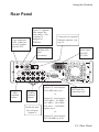
Rear Panel ................... . . . . . 3-3
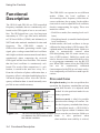
Functional Description . ............ . . 3-4
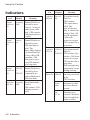
Indicators ................... . . . ... 3-6
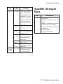
Satellite Strength Bars . ............ . . 3-7
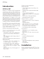
4 GPSView
Introduction .............. . ........ . 4-2
Installation .............. . ........ . 4-2
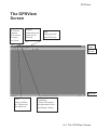
The GPSView Screen ... . . . . ......... 4-3
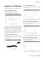
Graphs in GPSView ................. 4-9
5 Performance Check
General Information . . . . ........... . . 5-2
Preparations . . . . ................. . . 5-2
Front Panel Controls . . . . ........... . . 5-3
Rear Panel Outputs . . . . ........... . . 5-3
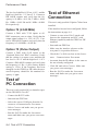
Test of PC Connection . . . . ........... 5-4
Test of Ethernet Connection . . . . ...... . 5-4
6 Preventive Maintenance
Calibration . . . . .................... 6-2
Fan Replacement . . . . .............. . 6-3
7 Specifications
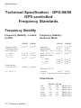
Frequency Stability . . . . .............. 7-2
Ordering Information . . . . ........... . . 7-6
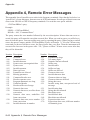
8 Appendix
Appendix 1, Antenna Installation . . . . ... 8-2
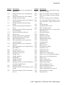
Appendix 2, Device Error Messages . . . . 8-9
Appendix 3, Command Reference . . . . . 8-10
Appendix 4, Remote Error Messages ... 8-44
9 Index
Index . . . . ......................... 9-2
10 Service
Sales and Service Office . . . . ...... . . 10-II
III
Environmental Considerations. ... . . . ... 2-4

Warranty
The Warranty Statement is part of the folder Important Information that is
included with the shipment.
IV

V
Declaration of Conformity
The complete text with formal statements concerning product identification,
manufacturer and standards used for type testing is available on request.
-

This page is intentionally left blank.
VI

Chapter 1
Preface

Introduction
Cesium-controlled Frequency
via GPS Satellites
The GPS-controlled frequency standards -
GPS-88 and GPS-89 - deliver a precision fre-
quency and time reference, everywhere in the
world. They receive their long-term frequency
stability from built-in Cesium standards in the
GPS-satellites. The GPS-88/89 are designed to
provide a very-high short-term stability. They
are cost-efficient, traceable and extremely accu-
rate frequency standards.
The GPS-88/89 are very suitable as
frequency standards in the telecom-
munication and electronics indus-
try. They fit in the calibration labo-
ratory, as frequency reference in test
systems and as a local reference in
the design department.
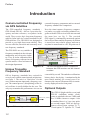
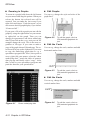
Unique Traceable
Frequency Standard
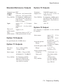
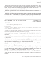
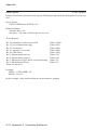
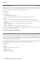
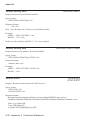
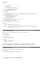
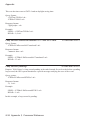
Off-air frequency standards have existed for
several years with the same internal architecture,
see figure 1. The unit is a “black box” for the
user, with an antenna input and a frequency out-
put. The control process (disciplining) of the lo-
cal oscillator is totally hidden for the user. The
only way to monitor the performance is to use an
external frequency comparator and an external
frequency standard for comparison.
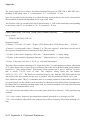
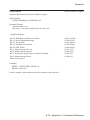
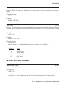
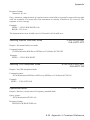
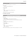
Now the timer/counter (frequency compara-
tor) and a very stable secondary standard is to-
gether with the GPS receiver built into one and
the same box, see fig. 2. The received
GPS-signal is continuously measured against
the local oscillator and the frequency deviation
is stored in a non-volatile storage and can at
any time be transferred to a PC for print-out of
a traceability record. The unbroken calibration
history chain - day by day - is maintained in the
non-volatile memory for several years. Fur-
thermore the current 24h mean offset is contin-
uously displayed on the front panel.
Optional Outputs
The GPS-88 (high-stability oven) and
GPS-89 (rubidium atomic clock)
come as standard with one 5 MHz and
five 10 MHz sinewave outputs. Also
as standard there is a 1 pps (one pulse
per second) output. There are four op-
tions to choose from, options 70, 71,
72 and option 75. Options 70, 71 and
1- 2
Preface
GPS-
Receiver
Refererence Out (10 MHz)
Phase
comparator
Local
os ci lla tor
(VCO)
Figure 1-1. A typical “black-box GPS-receiver.
GPS
Re ce iv er 10 and 5 MHzoutputs
Hi gh r eso lu ti o n
counter
Measurement
st or ag e
(Calibration data)
F r on t p an el di s pl a y of fr eq ue nc y o ffs et To PC ( RS2 3 2)
Rubidium
or O CX O
os c illa t or
Micr o pr oce ss or
1 pps
output opt.
other frequencies
programmable pul se
output opt.
Figure 1-2. The GPS-88/89 have built-in comparison
between the GPS-receiver and the internal
oscillator.

72 allow for five extra frequency outputs to be
mounted and are mutually exclusive.
Option 70 gives 5 extra 10 MHz outputs.
Option 71 gives four 1Vrms sine wave outputs
of resp. 10 MHz, 5 MHz, 1 MHz and 0.1 MHz,
plus a 0.1 MHz square wave output.
Option 72 gives five extra 2.048MHz outputs
for telecommunication testing and clock syn-
chronization (G.703:10)
Option 75 allows the user to define his own
pulse frequency output, as long as the pulse pe-
riod is an integer multiple of 100 ns.
Two Operating Modes
To fully eliminate long-term frequency changes
(aging) you should have an automatic adjust-
ment (known as disciplining). This disciplined
mode is the default mode in the GPS-88/89. As
long as there is a valid satellite signal, the inter-
nal local oscillator is monitored and adjusted.
When using the received GPS-signal for disci-
plining, the stability is reduced for averaging
times of 100s to 1000s.
The manual Hold-over mode removes the auto-
matic adjustment, thereby improving the
short-term stability. This mode is intended for
critical applications, like jitter and wander mea-
surements, where the frequency standard used,
must have an excellent short-term stability.
The manual Hold-over mode makes it possible
to temporarily switch over from disciplined to
Hold-over mode during the actual measurement,
thereby achieving a superior frequency accuracy
at the start of the measurement and a superior
stability through the measurement.
Made for Portability
When using manual Hold-over mode, the
GPS-88/89 acts like a stand-alone OCXO or Ru-
bidium frequency standard. This means that
GPS-88/89 are up and running after just 10
minutes after a change of location.
Best of Two Worlds
The GPS-88 and GPS-89 have a unique design
with a built-in measurement kernel for contin-
uous comparison of two independent fre-
quency sources; the received 1pps signal from
the GPS-satellites and the very high-stability
internal oscillator. Thanks to this design, the
very-high stability built-in Rubidium or
OCXO oscillator is continuously calibrated
and traceable to the primary frequency stan-
dards in the US Naval Observatory, and ulti-
mately to all national standards (e.g. NIST,
NPL, PTB, SP etc.) In the disciplined mode,
the calibration data is used to adjust the inter-
nal oscillator to fully compensate for the aging
of the local oscillator.
1- 3
Preface

This page is intentionally left blank.
1- 4
Preface

Chapter 2
Preparation for Use

Safety Instructions
Introduction
Read this page carefully before you install and
use the instrument.
This instrument has been designed and tested ac-
cording to safety Class 1 requirements of
EN61010-1 and CSA 22.2 No.1010.1, and has
been supplied in a safe condition. The user of
this instrument must have the required knowl-
edge of it. This knowledge can be gained by
thoroughly studying this manual.
This instrument is designed to be used by trained
personnel only. Removal of the cover for repair
or rack-mounting of the instrument must be
done by qualified personnel who are aware of
the hazards involved. There are no
user-serviceable parts inside the instrument.
Safety Precautions
To ensure the correct and safe operation of this
instrument, it is essential that you follow gener-
ally accepted safety procedures in addition to the
safety precautions specified in this manual.
Caution and Warning
Statements
CAUTION: Shows where incorrect
procedures can cause damage to,
or destruction of equipment or
other property.
WARNING: Shows a potential danger
that requires correct procedures or
practices to prevent personal injury.
Symbols
Shows where the protective ground ter-
minal is connected inside the instrument.
Never remove or loosen this screw.
Indicates that the operator should con-
sult the manual.
If in Doubt about Safety
Whenever you suspect that it is unsafe to use
the instrument, you must make it inoperative
by doing as follow
–Disconnect the line cord
–Clearly mark the instrument to prevent its
further operation
–Inform your local Pendulum Service Cen-
ter.
For example, the instrument is likely to be un-
safe if it is visibly damaged.
Fuse
A 1.6A/250V slow blow fuse is placed in the
internal power supply.
CAUTION: If this fuse is blown, it is
likely that the power supply is
badly damaged. Do not replace
the fuse. Send the instrument to
your local Service Center.
Grounding
Whenever an instrument is connected to the
line voltage, a grounding fault will make it po-
tentially dangerous. Before connecting any
2-2 Introduction
Preparation for Use

unit to the power line, you must make sure that
the protective ground functions correctly. Only
then can a unit be connected to the power line
and only by using a three-wire line cord. No
other method of grounding is permitted. Exten-
sion cords must always have a protective ground
conductor.
WARNING: If a unit is moved from a
cold to a warm environment, con-
densation may cause a shock
hazard. Ensure, therefore, that the
grounding requirements are strictly
met.
WARNING: Never interrupt the
grounding cord. Any interruption of
the protective ground connection
inside or outside the instrument or
disconnection of the protective
ground terminal is likely to make
the instrument dangerous.
2-3 Grounding
Preparation for Use
Do not operate in an
explosive atmosphere.
The instrument must not be placed in
potentially explosive atmospheres.
Do not operate near
flammable liquids
Do not operate the instrument in the presence
of flammable liquids or near containers of such
liquids.
Do not operate the
instruments in wet
environments
Under no circumstances should you operate the
instrument at the locations where there could
be a risk of water and other liquids penetrating.
Cleaning the instrument
Clean the machine only with soft, lint-free,
slightly-dampened cloth. Do not use
detergents or chemical solvents.
Do not modify the
instrument
Do not install replacement parts or make any
unauthorized modifications to the product.
Return the product to Pendulum’s service
office for repair to ensure that safety features
are maintained.
Terminals
WARNING: The BNC shells of the
input/output terminals are
connected to the instrument
chassis. Verify polarity before
making any connections to the
input/output terminals.
WARNING: IEC Measurement
Category I. Do NOT connect
inputs to AC mains or to
circuits derived from AC
mains.

This section provides information about the
environmental impact of the product.
Product End-of-Life Handling
Observe the following guidelines when
recycling an instrument or component:
Equipment recycling
Production of this equipment required the
extraction and use of natural resources. The
equipment may contain substances that could
be harmful to the environment or human
health if impropely handled at the product's
end of life. To avoid release of such
substances into the environment and to reduce
the use of natural resources, we encourage you
to recycle this product in an appropriate
system that will ensure that most of the
materials are reused or recycled appropriately.
This symbol indicates that this
product complies with European
Union requirements according to
Directives 2012/19/EU and
2006/66/EC on waste electrical
and electronic equipment
(WEEE) and batteries.
2-4 Environmental Considerations
Preparation for Use
Environmental Considerations

Unpacking
Unpacking
Instructions
Check that the shipment is complete and that no
damage has occurred during transportation. If
the contents are incomplete or damaged, file a
claim with the carrier immediately. Also notify
your local Pendulum sales or service office in
case repair or replacement may be required.
Check List
The shipment should contain the following:
–The frequency standard.
–Line cord.
–GPSView™ program disk.
–This Operators Manual.
–If you ordered one of the options 70, 71, 72
and/or the options 75, 76, they should al-
ready be installed. See “Identification” be-
low.
–Other options you ordered, e.g. antenna
(option 01), antenna cable (option 02), rack
mount kit (option 22) or carrying case (op-
tion 27/27H) are shipped in separate boxes.
–Certificate of Calibration.
Option 72: 5 BNC-connectors mounted in the
area designated “Option 72 Outputs”.
Option 75: 1 BNC-connector mounted in the
area designated “Optional Pulse Output”.
Option 76: 1 RJ45 Ethernet connector to the
right of the antenna input + 1 switch desig-
nated “Ethernet-RS232” to the left of the
RS232 connector.
Identification
Options installed inside the cover are identified
on the rear panel according to the list below.
Option 70: 5 BNC-connectors mounted in the
area designated “Optional 10 MHz Outputs”.
Option 71: 5 BNC-connectors mounted in the
area designated “Option 71 Outputs”.
Preparation for Use
2-5 Environmental Considerations

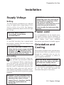
Installation
Supply Voltage
Setting
The GPS frequency standard may be connected
to any AC supply with a voltage rating of 100 to
240 Vac (±10%), 47 to 63 Hz. The frequency
standard automatically adjusts itself to the input
line volt-age.
Fuse
A 1.6A/250V slow-blow fuse is placed inside
the frequency standard. This fuse rating is used
for the full voltage range.
CAUTION: If this fuse is blown, it is
likely that the power supply is badly
damaged. do not replace the fuse.
Send the frequency standard to the
local Pendulum Service Center.
Grounding
Grounding faults in the line voltage sup-
ply will make any instrument connected
to it dangerous. Before connecting any
unit to the power line, you must make sure that
the protective ground functions correctly. Only
then can a unit be connected to the power line
and only by using a three-wire line cord. No
other method of grounding is permitted. Exten-
sion cords must always have a protective ground
conductor.
WARNING: If a unit is moved from a
cold to a warm environment, con-
densation may cause a shock
hazard. Ensure, therefore, that the
grounding requirements are
strictly met.
WARNING: Never interrupt the
grounding cord. Any interruption
of the protective ground connec-
tion inside or outside the
instrument or disconnection of the
protective ground terminal is
likely to make the instrument dan-
gerous.
Orientation and
Cooling
The frequency standard can be operated in any
position desired. Make sure that the air flow
through the ventilation slots are not ob-
structed. Leave 1 centimeter (½ inches) of
space around the GPS-88/89.
CAUTION: Never cover the ventila-
tion slots at the right or left side. If
the slots are covered, the fre-
quency standard will overheat.
2-6 Supply Voltage
Preparation for Use
CAUTION: Never connect a
line-voltage outside limits
described above.
Power cord
It is recommended to use the original power
cord supplied together with the instrument. In
case the power cord needs to be replaced,
please contact your local Pendulum
Instruments representative for further support.
The unit should be positioned in a way that
the user can access and disconnect the
instrument from power if necessary.

The GPS-88/89 Fan Control
The fan is used to adjust the temperature inside
the frequency standard to compensate for varia-
tions in ambient temperature.
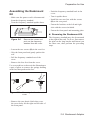
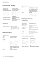
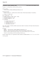
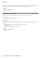
Fold-down Support
For bench-top use, a fold-down support is avail-
able for use underneath the frequency standard.
This support can also be used as a handle to carry
the instrument.
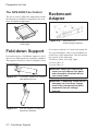
Rackmount
Adapter
If you have ordered a 19 inch rack mount kit
for your instrument, it has to be assembled af-
ter delivery of the instrument. The rack mount
kit consists of the following:
2 brackets, (short, left; long, right)
4 screws, M5 x 8
4 screws, M6 x 8
WARNING: When you remove the
cover you will expose live parts
and accessible terminals which
can cause death.
WARNING: Capacitors inside the in-
strument can hold their charge
even if the instrument has been
separated from all voltage
sources.
2-7 Fold-down Support
Preparation for Use
Figure 2-1 Air flow through the
GPS-88/89.
Figure 2-2 Fold-down support for comfort-
able bench-top use.
Figure 2-3 Use the support to carry the
frequency standard.
Figure 2-4 Dimensions for
rackmounting hardware.

Assembling the Rackmount
Kit
–Make sure the power cord is disconnected
from the frequency standard.
–Turn the frequency standard upside down.
–Loosen the two screws (B) in the rear feet.
–Grip the front panel and gently push at the
rear.
–Pull the frequency standard out of the
cover.
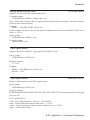
–Remove the four feet from the cover.
Use a screwdriver as shown in the illustration or
a pair of pliers to remove the springs holding
each foot, then push out the feet.
–Remove the two plastic labels that cover
the screw holes on the right and left side of
the front panel.
–Push the frequency standard back in the
cover.
–Turn it upside down.
–Install the two rear feet with the screws
(B) to the rear panel.
–Fasten the brackets at the left and right
side with the screws included.
–Fasten the front panel and mounting plate.
nReversing the Rackmount Kit
The frequency standard may also be mounted
to the right in the rack. To do so, first remove
the plate on the long bracket and fasten it on
the short one, then perform the preceding
steps.
2-8 Rackmount Adapter
Preparation for Use
Figure 2-5 Removing feet from the
cover.
A
B
B
Figure 2-6 Remove the screws and
push out the frequency
standard from the cover.

Antenna Installation
The antenna (option 01), is intended for outdoor
mounting on a wall or preferably on a roof. The
more free sky that is visible from the antennas
position, the better the satellite contact.
The antenna cable is a 20 meter (option 02) or
50 m (option 02/50) high quality RG213 cable
that connects in one end to the antenna and in the
other end to the rear panel of the frequency stan-
dard. For installation details and instructions on
connecting other antennas/cables than those
supplied by Pendulum, please consult Appendix
2 in this manual.
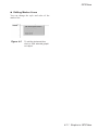
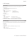
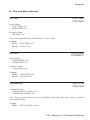
Connecting to a PC
A PC is connected to the RS232-port at the rear
of the instrument. A cable for connecting to a PC
should have female DB9-connectors in both
ends and be designed as a “null-modem” cable.
Optional Ethernet
Connection
(Option 76)
After configuration by means of the GPSView
SW over the standard RS232 interface, Option
76 lets the operator communicate with the
GPS frequency standard in much the same
way as with any Ethernet node. Remote con-
trol and data logging over Internet is thus a
simple task.
Standard Cat 5 patch cords of good quality
with RJ45 connectors can be used.
Note: There are two types available,
straight-through and cross-wired. The first one
is used when connecting to a wall outlet or a
hub, the second one when connecting directly
to a PC or other controller.
2-9 Antenna Installation
Preparation for Use
Figure 2-7 Connecting to a PC

Chapter 3
Using the Controls
Page is loading ...
Page is loading ...
Page is loading ...
Page is loading ...
Page is loading ...
Page is loading ...
Page is loading ...
Page is loading ...
Page is loading ...
Page is loading ...
Page is loading ...
Page is loading ...
Page is loading ...
Page is loading ...
Page is loading ...
Page is loading ...
Page is loading ...
Page is loading ...
Page is loading ...
Page is loading ...
Page is loading ...
Page is loading ...
Page is loading ...
Page is loading ...
Page is loading ...
Page is loading ...
Page is loading ...
Page is loading ...
Page is loading ...
Page is loading ...
Page is loading ...
Page is loading ...
Page is loading ...
Page is loading ...
Page is loading ...
Page is loading ...
Page is loading ...
Page is loading ...
Page is loading ...
Page is loading ...
Page is loading ...
Page is loading ...
Page is loading ...
Page is loading ...
Page is loading ...
Page is loading ...
Page is loading ...
Page is loading ...
Page is loading ...
Page is loading ...
Page is loading ...
Page is loading ...
Page is loading ...
Page is loading ...
Page is loading ...
Page is loading ...
Page is loading ...
Page is loading ...
Page is loading ...
Page is loading ...
Page is loading ...
Page is loading ...
Page is loading ...
Page is loading ...
Page is loading ...
Page is loading ...
Page is loading ...
Page is loading ...
Page is loading ...
Page is loading ...
Page is loading ...
Page is loading ...
Page is loading ...
Page is loading ...
Page is loading ...
Page is loading ...
Page is loading ...
Page is loading ...
Page is loading ...
Page is loading ...
Page is loading ...
Page is loading ...
Page is loading ...
Page is loading ...
Page is loading ...
Page is loading ...
Page is loading ...
Page is loading ...
-
 1
1
-
 2
2
-
 3
3
-
 4
4
-
 5
5
-
 6
6
-
 7
7
-
 8
8
-
 9
9
-
 10
10
-
 11
11
-
 12
12
-
 13
13
-
 14
14
-
 15
15
-
 16
16
-
 17
17
-
 18
18
-
 19
19
-
 20
20
-
 21
21
-
 22
22
-
 23
23
-
 24
24
-
 25
25
-
 26
26
-
 27
27
-
 28
28
-
 29
29
-
 30
30
-
 31
31
-
 32
32
-
 33
33
-
 34
34
-
 35
35
-
 36
36
-
 37
37
-
 38
38
-
 39
39
-
 40
40
-
 41
41
-
 42
42
-
 43
43
-
 44
44
-
 45
45
-
 46
46
-
 47
47
-
 48
48
-
 49
49
-
 50
50
-
 51
51
-
 52
52
-
 53
53
-
 54
54
-
 55
55
-
 56
56
-
 57
57
-
 58
58
-
 59
59
-
 60
60
-
 61
61
-
 62
62
-
 63
63
-
 64
64
-
 65
65
-
 66
66
-
 67
67
-
 68
68
-
 69
69
-
 70
70
-
 71
71
-
 72
72
-
 73
73
-
 74
74
-
 75
75
-
 76
76
-
 77
77
-
 78
78
-
 79
79
-
 80
80
-
 81
81
-
 82
82
-
 83
83
-
 84
84
-
 85
85
-
 86
86
-
 87
87
-
 88
88
-
 89
89
-
 90
90
-
 91
91
-
 92
92
-
 93
93
-
 94
94
-
 95
95
-
 96
96
-
 97
97
-
 98
98
-
 99
99
-
 100
100
-
 101
101
-
 102
102
-
 103
103
-
 104
104
-
 105
105
-
 106
106
-
 107
107
-
 108
108


Ask a question and I''ll find the answer in the document
Finding information in a document is now easier with AI
Related papers


Other documents
-
Symmetricom ET6500-TCXO User manual
-
-
 Orolia 8194 GPS Ageless Oscillator User manual
-
 Orolia GPS Ageless Master Oscillator 8194B, 8195B, 8197B User manual
-
 Orolia SecureSync 1200 Time and Frequency Synchronization System User manual
-
 Orolia SecureSync Time and Frequency Synchronization System User manual
-
 Orolia NetClock 9400 Series Time Server User manual
-
 Orolia SecureSync 2400 Time and Frequency Synchronization System User manual
-
 Orolia 8197 GPS Ageless Master Oscillator User manual
-
 Orolia 8195A GPS Ageless Oscillator User manual


