Page is loading ...

GPS AGELESS
®
MASTER OSCILLATOR
MODEL 8194B, 8195B, 8197B
INSTRUCTION MANUAL
SPECTRACOM CORPORATION
95 METHODIST HILL DRIVE
ROCHESTER, NY 14623
PHONE +1.585.321.5800
FAX +1.585.321.5219
www.spectracomcorp.com
Part Number 1132-5000-0050
Manual Revision D
August 2007

Copyright © 2007 Spectracom Corporation. The contents of this publication may not be
reproduced in any form without the written permission of Spectracom Corporation. Printed in
USA.
Specifications subject to change or improvement without notice.
Spectracom, NetClock, Ageless, TimeGuard, TimeBurst, TimeTap, LineTap, MultiTap,
VersaTap, and Legally Traceable Time are Spectracom registered trademarks. All other
products are identified by trademarks of their respective companies or organizations. All rights
reserved.

SPECTRACOM 95 Methodist Hill Drive Rochester, NY 14623
+1.585.321.5800 FAX: +1.585.321.5218 www.spectracomcorp.com sa[email protected]
SPECTRACOM LIMITED WARRANTY
LIMITED WARRANTY
Spectracom warrants each new product manufactured and
sold by it to be free from defects in software, material,
workmanship, and construction, except for batteries, fuses, or
other material normally consumed in operation that may be
contained therein AND AS NOTED BELOW, for five years after
shipment to the original purchaser (which period is referred to
as the “warranty period”). This warranty shall not apply if the
product is used contrary to the instructions in its manual or is
otherwise subjected to misuse, abnormal operations, accident,
lightning or transient surge, repairs or modifications not
performed by Spectracom.
The GPS receiver is warranted for one year from date of
shipment and subject to the exceptions listed above. The
power adaptor, if supplied, is warranted for one year from date
of shipment and subject to the exceptions listed above.
THE ANALOG CLOCKS ARE WARRANTED FOR TWO
YEARS FROM DATE OF SHIPMENT AND SUBJECT TO THE
EXCEPTIONS LISTED ABOVE.
THE TIMECODE READER/GENERATORS ARE WARRANT-
ED FOR ONE YEAR FROM DATE OF SHIPMENT AND
SUBJECT TO THE EXCEPTIONS LISTED ABOVE.
The Rubidium oscillator, if supplied, is warranted for two years
from date of shipment and subject to the exceptions listed
above.
All other items and pieces of equipment not specified above,
including the antenna unit, antenna surge suppressor and
antenna pre-amplifier are warranted for 5 years, subject to the
exceptions listed above.
WARRANTY CLAIMS
Spectracom’s obligation under this warranty is limited to in-
factory service and repair, at Spectracom’s option, of the
product or the component thereof, which is found to be
defective. If in Spectracom’s judgment the defective condition
in a Spectracom product is for a cause listed above for which
Spectracom is not responsible, Spectracom will make the
repairs or replacement of components and charge its then
current price, which buyer agrees to pay.
Spectracom shall not have any warranty obligations if the
procedure for warranty claims is not followed. Users must
notify Spectracom of the claim with full information as to the
claimed defect. Spectracom products shall not be returned
unless a return authorization number is issued by Spectracom.
Spectracom products must be returned with the description of
the claimed defect and identification of the individual to be
contacted if additional information is needed. Spectracom
products must be returned properly packed with transportation
charges prepaid.
Shipping expense: Expenses incurred for shipping
Spectracom products to and from Spectracom (including
international customs fees) shall be paid for by the customer,
with the following exception. For customers located within the
United States, any product repaired by Spectracom under a
“warranty repair” will be shipped back to the customer at
Spectracom’s expense unless special/faster delivery is
requested by customer.
Spectracom highly recommends that prior to returning
equipment for service work, our technical support department
be contacted to provide trouble shooting assistance while the
equipment is still installed. If equipment is returned without
first contacting the support department and “no problems are
found” during the repair work, an evaluation fee may be
charged.
EXCEPT FOR THE LIMITED WARRANTY STATED ABOVE,
SPECTRACOM DISCLAIMS ALL WARRANTIES OF ANY
KIND WITH REGARD TO SPECTRACOM PRODUCTS OR
OTHER MATERIALS PROVIDED BY SPECTRACOM,
INCLUDING WITHOUT LIMITATION ANY IMPLIED
WARRANTY OR MERCHANTABILITY OR FITNESS FOR A
PARTICULAR PURPOSE.
Spectracom shall have no liability or responsibility to the
original customer or any other party with respect to any liability,
loss, or damage caused directly or indirectly by any
Spectracom product, material, or software sold or provided by
Spectracom, replacement parts or units, or services provided,
including but not limited to any interruption of service, excess
charges resulting from malfunctions of hardware or software,
loss of business or anticipatory profits resulting from the use or
operation of the Spectracom product or software, whatsoever
or howsoever caused. In no event shall Spectracom be liable
for any direct, indirect, special or consequential damages
whether the claims are grounded in contract, tort (including
negligence), or strict liability.
EXTENDED WARRANTY COVERAGE
Extended warranties can be purchased for additional periods
beyond the standard five-year warranty. Contact Spectracom
no later than the last year of the standard five-year warranty for
extended coverage.


Spectracom Corporation 8194B, 8195B, 8197B
GPS Ageless Master Oscillator Instruction Manual iii
Table of Contents
1 GENERAL INFORMATION ..................................................................... 1-1
1.1 Introduction....................................................................................................................................1-1
1.2 Features........................................................................................................................................1-1
1.3 Warranty Information and Product Support...................................................................................1-3
1.4 Manual Errata and Special Documentation...................................................................................1-4
1.5 Unpacking......................................................................................................................................1-4
1.6 Specifications................................................................................................................................1-5
1.6.1 Receiver........................................................................................................................................1-5
1.6.2 Standard Frequency Outputs.........................................................................................................1-5
1.6.3 Ovenized Oscillator Frequency Stability........................................................................................1-6
1.6.4 Rubidium Oscillator Frequency Stability........................................................................................1-7
1.6.5 1PPS Output..................................................................................................................................1-7
1.6.6 1544 kHz Timing Outputs..............................................................................................................1-8
1.6.7 2048 kHz Timing Outputs..............................................................................................................1-8
1.6.8 Data Clock Timing Outputs............................................................................................................1-9
1.6.9 Data Sync Timing Outputs.............................................................................................................1-9
1.6.10 Indicator Lamps...........................................................................................................................1-10
1.6.11 Alarms.........................................................................................................................................1-10
1.6.12 Communication Ports..................................................................................................................1-14
1.6.13 Input Power.................................................................................................................................1-14
1.6.14 Mechanical..................................................................................................................................1-15
1.6.15 Environmental..............................................................................................................................1-15
1.6.16 Agency Approval .........................................................................................................................1-15
1.6.17 Model 8225 GPS Antenna Specifications....................................................................................1-16
2 INSTALLATION ..................................................................................... 2-1
2.1 Introduction....................................................................................................................................2-1
2.2 Model 8225 GPS Antenna.............................................................................................................2-1
2.2.1 Antenna Installation.......................................................................................................................2-1
2.3 Antenna Cable...............................................................................................................................2-2
2.3.1 Cable Lengths............................................................................................................
...................2-3
2.4 Model 8226 Impulse Suppressor...................................................................................................2-3
2.5 Model 8227 GPS Inline Amplifier...................................................................................................2-6
2.6 Master Oscillator Preparation for Use............................................................................................2-8
2.6.1 Antenna Connection......................................................................................................................2-8
2.6.2 AC Power......................................................................................................................................2-8
2.6.3 DC Power......................................................................................................................................2-9
2.6.4 Chassis Ground.............................................................................................................................2-9
2.7 Initial Operation ...........................................................................................................................2-10
2.8 Qualifying the Installation.............................................................................................................2-10
2.8.1 GPS Signal Status.......................................................................................................................2-11
2.8.2 Tracking Histogram .....................................................................................................................2-12
2.9 Reception Troubleshooting..........................................................................................................2-13
2.9.1 No Reception...............................................................................................................................2-13
2.9.2 Low GPS Quality.........................................................................................................................2-15

8194B, 8195B, 8197B Spectracom Corporation
GPS Ageless Master Oscillator Instruction Manual iv
2.10 Default Factory Configuration......................................................................................................2-15
3 OPERATION .......................................................................................... 3-1
3.1 Introduction....................................................................................................................................3-1
3.2 Front Panel Functions ...................................................................................................................3-1
3.2.1 Status Lamps.................................................................................................................................3-1
3.2.2 Alarm Lamps.................................................................................................................................3-1
3.2.3 Battery Lamps (Option 02 only).....................................................................................................3-4
3.2.4 RS-232 Com..................................................................................................................................3-4
3.2.5 10 MHz Output..............................................................................................................................3-5
3.2.6 1PPS Output..................................................................................................................................3-5
3.3 Rear Panel Functions....................................................................................................................3-6
3.3.1 GPS Antenna.................................................................................................................................3-6
3.3.2 Frequency Outputs........................................................................................................................3-6
3.3.3 1544 kHz and 2048 kHz Timing Outputs.....................................................................................3-10
3.3.4 Data Clock Timing Outputs..........................................................................................................3-12
3.3.5 Set Up Switches..........................................................................................................................3-14
3.3.6 RS-485 COM...............................................................................................................................3-15
3.3.7 Data Sync Timing Outputs...........................................................................................................3-16
3.3.8 Major Alarm Contacts..................................................................................................................3-18
3.3.9 Alarm Outputs..............................................................................................................................3-18
3.3.10 DC Power....................................................................................................................................3-20
3.3.11 AC Power....................................................................................................................................3-21
3.3.12 Cooling fan..................................................................................................................................3-22
3.3.13 Chassis Ground...........................................................................................................................3-22
3.3.14 Battery Disconnect Switch...........................................................................................................3-22
4 SOFTWARE COMMANDS....................................................................... 4-1
4.1 Introduction....................................................................................................................................4-1
4.2 RS-232 Commands.......................................................................................................................4-1
4.3 RS-232 Command descriptions.....................................................................................................4-2
4.3.1 Antenna Cable Delay.....................................................................................................................4-3
4.3.2 Alarm Timeouts.............................................................................................................................4-4
4.3.3 Battery Status (Option 02 only)......................................................................................................4-5
4.3.4 Clear Alarm....................................................................................................................................4-5
4.3.5 Configuration.................................................................................................................................4-6
4.3.6 Display Alarm Log .........................................................................................................................4-7
4.3.7 Date ..............................................................................................................................................4-8
4.3.8 Display Frequency Measurements................................................................................................4-9
4.3.9 Display Oscillator Log....................................................................................................................4-9
4.3.10 Display Tracking Histogram.........................................................................................................4-12
4.3.11 Event Output................................................................................................................................4-13
4.3.12 GPS Signal Status.......................................................................................................................4-14
4.3.13 Help ............................................................................................................................................4-17
4.3.14 Location.......................................................................................................................................4-18
4.3.15 Signature Control.........................................................................................................................4-19
4.3.16 Set Mode.....................................................................................................................................4-19
4.3.17 Status Information .......................................................................................................................4-20

Spectracom Corporation 8194B, 8195B, 8197B
GPS Ageless Master Oscillator Instruction Manual v
4.3.18 Time ............................................................................................................................................4-20
4.3.19 Test Mode....................................................................................................................................4-21
4.3.20 Time Zone Offset.........................................................................................................................4-22
4.3.21 UTC To GPS Time ......................................................................................................................4-23
4.3.22 Version........................................................................................................................................4-23
4.3.23 Frequency Offset.........................................................................................................................4-24
4.3.24 1PPS Offset.................................................................................................................................4-26
4.4 RS-485 Command Structure .......................................................................................................4-27
4.5 RS-485 Command Descriptions..................................................................................................4-28
4.5.1 Antenna Cable Delay...................................................................................................................4-29
4.5.2 Alarm Event History.....................................................................................................................4-29
4.5.3 Alarm Status................................................................................................................................4-30
4.5.4 Alarm Timeouts...........................................................................................................................4-30
4.5.5 Clear Alarm History .....................................................................................................................4-30
4.5.6 GPS Signal Status.......................................................................................................................4-31
4.5.7 Location.......................................................................................................................................4-32
4.5.8 Signal Selection...........................................................................................................................4-33
4.5.9 Short Status.................................................................................................................................4-33
4.5.10 Time And Date.............................................................................................................................4-33
4.5.11 Time Zone Offset.........................................................................................................................4-34
4.5.12 Who – Model Identification..........................................................................................................4-34
4.5.13 10MHz Offset...............................................................................................................................4-35
4.5.14 1PPS Offset.................................................................................................................................4-36
5 OPTIONS AND ACCESSORIES ............................................................... 5-1
5.1 Introduction....................................................................................................................................5-1
5.2 Option 02 - Internal Battery Backup...............................................................................................5-1
5.2.1 Frequency Lock Recovery.............................................................................................................5-2
5.2.2 Battery Lamps...............................................................................................................................5-2
5.2.3 Clear Battery Alarm.......................................................................................................................5-3
5.2.4 Option 02 Specifications................................................................................................................5-3
5.3 Option 03 Built-in Distribution Amplifier.........................................................................................5-3
5.3.1 System Components.....................................................................................................................5-4
5.3.2 Design of Distribution Networks.....................................................................................................5-7
5.4 OPTION 06 – 12.8 MHZ outputs ...................................................................................................5-9
5.5 OPTION 07 – 5 MHZ outputs......................................................................................................5-10
5.6 OPTION 11 – Rack Mount Slides................................................................................................5-10
5.7 OPTION 14 - CTCSS Outputs One and Two...............................................................................5-12
5.7.1 Data Sync Timing Outputs...........................................................................................................5-12
5.7.2 Data Sync Alarm Contacts...........................................................................................................5-13
5.7.3 RS-485 Timing Signals................................................................................................................5-14
5.7.4 RS-232 CTCSS Configuration.....................................................................................................5-14
5.7.5 RS-485 CTCSS Configuration.....................................................................................................5-16
5.7.6 Model 1118 CTCSS.....................................................................................................................5-16
5.8 OPTION 16 – 1PPS Rear Panel Frequency Outputs...................................................................5-20
5.9 OPTION 17 – CTCSS Outputs Three and Four...........................................................................5-21
5.10 OPTION SP294 – DS1 Framed All Ones....................................................................................5-22
5.11 OPTION SP295 – E1 Framed All Ones.......................................................................................5-24

8194B, 8195B, 8197B Spectracom Corporation
GPS Ageless Master Oscillator Instruction Manual vi
6 SERVICE INFORMATION ....................................................................... 6-1
6.1 Introduction....................................................................................................................................6-1
6.2 Battery Replacement.....................................................................................................................6-1
6.2.1 Battery Replacement Instructions..................................................................................................6-1
6.3 OCXO Oscillator Adjustment (8194B and 8195B ONLY)...............................................................6-3
6.3.1 OCXO Adjustment Procedure (8194B and 8195B ONLY).............................................................6-4
A.1 Appendix A...........................................................................................A-1
A.1 Introduction................................................................................................................................... A-1
A.2 GPS qualifying algorithm selection............................................................................................... A-2
A.3 GQA Command............................................................................................................................ A-3
List of Figures
Figure 1-1 Spectracom Ageless Master Oscillator......................................................................................1-1
Figure 2-1 Antenna Installation...................................................................................................................2-2
Figure 2-2 Model 8226 Impulse Suppressor...............................................................................................2-3
Figure 2-3 Grounding Panel Installation .....................................................................................................2-4
Figure 2-4 N Connector Assembly Instructions...........................................................................................2-6
Figure 2-5 Model 8227 Inline Amplifier.......................................................................................................2-6
Figure 2-6 Cable Guidelines.......................................................................................................................2-7
Figure 2-7 DC Backup Wiring.....................................................................................................................2-8
Figure 2-8 DC Power Connector.................................................................................................................2-9
Figure 3-1 Spectracom Master Oscillator Front Panel................................................................................3-3
Figure 3-2 RS-232 Com Pin Numbering.....................................................................................................3-5
Figure 3-3 Spectracom Master Oscillator Model 8195B and 8197B Rear Panel........................................3-7
Figure 3-4 Spectracom Master Oscillator Model 8194B Rear Panel...........................................................3-8
Figure 3-5 Timing Output Connector........................................................................................................3-10
Figure 3-6 RS-485 Output........................................................................................................................3-11
Figure 3-7 Single-Ended Connection........................................................................................................3-12
Figure 3-8 Data Clock Connector.............................................................................................................3-12
Figure 3-9 RS-485 Line Driver..................................................................................................................3-13
Figure 3-10 RS458 COM Connector.........................................................................................................3-15
Figure 3-11 RS-485 Connection...............................................................................................................3-16
Figure 3-12 Data Sync Connector............................................................................................................3-16
Figure 3-13 Data Sync Drivers .................................................................................................................3-18
Figure 3-14 Alarm Outputs Terminal Block...............................................................................................3-19
Figure 3-15 DC Backup Wiring.................................................................................................................3-20
Figure 3-16 DC Power Connector.............................................................................................................3-21
Figure 3-17 AC Power Module .................................................................................................................3-22
Figure 4-1 Command Structure..................................................................................................................4-1
Figure 5-1 Line Tap Number and Distance Chart..................................................................................
.....5-8
Figure 5-2 Typical Interconnection Diagram...............................................................................................5-9
Figure 5-3 Slides Assembly......................................................................................................................5-11
Figure 5-4 Data Sync Connector..............................................................................................................5-12
Figure 5-5 Data Sync Drivers ...................................................................................................................5-14
Figure 5-6 Data Clock Connector.............................................................................................................5-21

Spectracom Corporation 8194B, 8195B, 8197B
GPS Ageless Master Oscillator Instruction Manual vii
Figure 5-7 DS1 Framed All Ones Connector............................................................................................5-22
Figure 5-8 Frame Selection Jumper.........................................................................................................5-22
Figure 5-9 Programmable Jumper Locations............................................................................................5-23
Figure 5-10 E1 Framed All Ones Connector.............................................................................................5-24
Figure 5-11 Frame Selection Jumpers......................................................................................................5-24
Figure 5-12 Programmable Jumper Locations..........................................................................................5-25
List of Tables
Table 1-1 Product Comparison Table.........................................................................................................1-2
Table 1-2 Ancillary Kits...............................................................................................................................1-4
Table 2-1 DC Power Configurations...........................................................................................................2-9
Table 2-2 Typical Antenna Cable Resistance Values...............................................................................2-13
Table 2-3 Default Setting..........................................................................................................................2-15
Table 3-1 RS-232 Com Pin Assignments...................................................................................................3-5
Table 3-2 UHF Simulcast Offsets...............................................................................................................3-9
Table 3-3 VHF HI Simulcast Offsets...........................................................................................................3-9
Table 3-4 Timing Output Pin Assignments ...............................................................................................3-11
Table 3-5 Data Clock Pin Assignments....................................................................................................3-12
Table 3-6 Address Selection.....................................................................................................................3-14
Table 3-7 RS-485 COM Pin Assignments ................................................................................................3-15
Table 3-8 Data Sync Pin Assignments.....................................................................................................3-17
Table 3-9 Alarm Operation .......................................................................................................................3-19
Table 3-10 DC Power Configurations.......................................................................................................3-20
Table 4-1 Alphabetical List of RS-232 Commands.....................................................................................4-2
Table 4-2 Common Offset Values.............................................................................................................4-22
Table 4-3 UHF Simulcast Offsets SC1.....................................................................................................4-24
Table 4-4 VHF HI Simulcast Offsets SC2.................................................................................................4-24
Table 4-5 RS-485 Command Protocol......................................................................................................4-27
Table 4-6 Alphabetical List of RS-485 Commands...................................................................................4-28
Table 4-7 Common Offset Values.............................................................................................................4-34
Table 4-8 UHF Simulcast Offsets.............................................................................................................4-35
Table 4-9 VHF Simulcast Offsets..............................................................................................................4-36
Table 5-1 Line Tap Loads...........................................................................................................................5-7
Table 5-2 Option 11 Checklist ..................................................................................................................5-10
Table 5-3 Option 14 Data Sync Pin Assignments.....................................................................................5-12
Table 5-4 CTCSS #1 and CTCSS #2 Frequency List...............................................................................5-13
Table 5-5 CTCSS Tones List – CTCSS #1 & #2.......................................................................................5-15
Table 5-6 CTCSS Standard Frequency Chart..........................................................................................5-17
Table 5-7 Option 17 Data Sync Pin Assignments.....................................................................................5-21
Table 5-8 CTCSS Tones List – CTCSS #3 & #4.......................................................................................5-21
Table A-1 Television Stations with GPS Jamming Potential...................................................................... A-1
Table A-2 FM Radio Frequencies with GPS Jamming Potential................................................................ A-1

8194B, 8195B, 8197B Spectracom Corporation
GPS Ageless Master Oscillator Instruction Manual viii

Spectracom Corporation 8194B, 8195B, 8197B
GPS Ageless Master Oscillator Instruction Manual 1
-
1
1 General Information
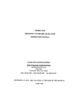
1.1 Introduction
The patented Spectracom Ageless
®
Master Oscillator*, shown in Figure 1-1, is a highly
accurate frequency source available in oven-stabilized crystal oscillator (OCXO) and
Rubidium versions. Its outputs are locked to the United States Naval Observatory via
the NAVSTAR Global Positioning System (GPS). Spectracom’s field-proven Ageless
Oscillator technology provides continual automatic frequency control. A long-term
averaging algorithm compensates for oscillator aging and temperature drift.
The Spectracom Ageless Master Oscillator is ideally suited as a site master oscillator
for communication systems. Typical transmitter applications include land mobile
simulcast, SMR (Specialized Mobile Radio), paging simulcast, satellite/microwave
communications links, cellular telephone, and broadcast television.
Figure 1-1 Spectracom Ageless Master Oscillator
1.2 Features
The Master Oscillator offers the following features:
• Accuracy: Continuous self-calibration to GPS provides ± 1.0 x 10
-11
frequency
accuracy with the OCXO versions and ± 1.0 x 10
-12
frequency accuracy for Rubidium
version.
• Precise Offsets: The Model 8194B/8195B disciplined 10 MHz outputs can be offset
in precise steps to improve VHF - Hi simulcast.
* PATENT NO. 4,525,685

8194B, 8195B, 8197B Spectracom Corporation
GPS Ageless Master Oscillator Instruction Manual 1-2
• Reliable Worldwide Operation: The Master Oscillator can receive and track up to
twelve satellites simultaneously. Receivers qualify the received GPS broadcast
using T-RAIM. T-RAIM, Time Receiver Autonomous Integrity Monitoring is an
algorithm that disqualifies a satellite from a solution if its message is not within a
reasonable window of other satellites currently tracked.
• Flexibility: Several power and output options are available to suit various
applications. Refer to Table 1-1 for a comparison of product features and available
options.
S = Standard, O = Option Available, NA = Not Available
Ageless GPS Master Oscillator
Model 8195B Model 8197B Model 8194B
Standard Features
Oscillator
Quartz S NA S
Rubidium NA S NA
Front Panel
(1) 10 MHz S S S
(1) 1 PPS S S S
(1) RS-232 Comm Port S S S
Rear Panel
(4) 10 MHz Output S S S
(1) Timing Output 1544 kHz S S NA
(1) Timing Output 2048 kHz S S NA
(1) Data Clock Output (including disciplined 1 PPS) S S S
(1) Data Sync Output S S NA
(1) RS-485 Comm Port S S NA
Software Features
Simulcast Frequency Offset S NA S
Fast Frequency Lock Recovery S (w/ Opt 02) NA S (w/ Opt 02)
Available Options
02 – Internal Battery O (w/ AC only) NA O (w/ AC only)
03 – Internal Frequency Distribution Amplifier O O O
06 – 12.8 MHz Outputs O O NA
07 – 5 MHz Outputs O O O
11 – Mounting Slides O O O
14 – CTCSS Outputs One and Two O O NA
16 – 1PPS on Third and Fourth Rear Panel
Frequency Output O O NA
17 – CTCSS Outputs Three and Four O O NA
52 – 12 VDC Power O O O
53 – 24 VDC Power O O O
54 – 48 VDC Power O O O
SP294 – Adds (2) DS1 outputs
O
(NA w/ Opt 02)
O NA
SP295 – Adds (2) E1 outputs
O
(NA w/ Opt 02) O NA
Table 1-1 Product Comparison Table

Spectracom Corporation 8194B, 8195B, 8197B
GPS Ageless Master Oscillator Instruction Manual 1
-
3
1.3 Warranty Information and Product Support
Warranty information is found on the leading pages of this manual. This product
includes component assemblies that are not manufactured by Spectracom Corporation.
The components listed below shall carry the original manufacturer’s warranty.
• The GPS receiver carries a one-year warranty.
• The Rubidium oscillator carries a two-year warranty.
The remainder of the product is covered under Spectracom’s five-year warranty.
Should it become necessary to exercise the warranty, contact Spectracom Corporation
to obtain a replacement or service.
Spectracom continuously strives to improve its products and therefore greatly
appreciates any and all customer feedback given. Please participate in Spectracom’s
Customer Satisfaction Survey found on our web site:
http://www.spectracomcorp.com
Technical support is available by telephone, e-mail, or online. Please direct any
comments or questions regarding application, operation, or service to Spectracom
Customer Service Department. Customer Service is available Monday through Friday
from 8:30 A. M. to 5:00 P.M. Eastern time.
Telephone Customer Service at: 585.321.5800.
In addition, please contact Customer Service to obtain a Return Material Authorization
Number (RMA#) before returning any instrument to Spectracom Corporation. Please
provide the serial number and failure symptoms. Transportation to the factory is to be
prepaid by the customer. After obtaining an RMA#, ship the unit back to the following
address:
Spectracom Corporation
Repair Department, RMA# xxxxx
95 Methodist Hill Drive
Rochester, NY 14623
Product support is also available by e-mail. Questions on equipment operation and
applications may be e-mailed to Spectracom Sales Support at:
Repair or technical questions may be e-mailed to Spectracom technicians at:

8194B, 8195B, 8197B Spectracom Corporation
GPS Ageless Master Oscillator Instruction Manual 1-4
Visit our web page for product information, application notes and upgrade notices as
they become available at:
http://www.spectracomcorp.com
1.4 Manual Errata and Special Documentation
Information concerning manual corrections or product changes occurring after printing is
found in the Errata Section. The Errata Section, when required, is found at the end of
this manual. Please review and incorporate changes into the manual whenever an
Errata Section is included.
Spectracom will make instrument modifications on special request. A documentation
packet associated with the modification will be provided in addition to this manual.
1.5 Unpacking
On receipt, carefully examine the carton and its contents. If there is damage to the
carton resulting in damage to the unit, contact the carrier immediately. Retain the carton
and packing materials in the event the carrier wishes to witness the shipping damage.
Failing to report shipping damage immediately may forfeit any claim against the carrier.
In addition, notify Spectracom Corporation of shipping damage or shortages to obtain a
replacement or repair services.
Remove the packing list from the envelope on the outside of the carton. Check the
packing list against the contents to be sure all items have been received, including an
instruction manual and ancillary kit. Table 1-2 lists the items included in the various
ancillary kits. Please note that all items included in the ancillary kit may not be required
for some configurations of the product. For example, a line cord is not required on units
equipped with DC input power Options 52, 53 and 54. Replace fuses with only the
same type and rating as originally installed for the product configuration.
Description Part Number Standard Option 03 Distribution
Fuse, 2.0A Slo-Blo F012R0 1 1
Fuse, 1.5A Slo-Blo F011R5 1 1
Fuse, 10.0A F0010R 1 1
Fuse, 6.25A Slo-Blo F016R0 1 1
Fuse, 3.0A Slo-Blo F013R0 1 1
Line Cord W01000 1 1
Terminal Block,
6-position
P13006 1 1
Terminal Block,
7 position
P13007 1 1
Terminator, 50-ohm 004492 4 0
Terminator,
DC isolated
8140-0000-
1000
0 4
RS-232 Cable 050008 1 1
Table 1-2 Ancillary Kits

Spectracom Corporation 8194B, 8195B, 8197B
GPS Ageless Master Oscillator Instruction Manual 1
-
5
1.6 Specifications
This section contains specifications for the standard Master Oscillator, Model 8225 GPS
Antenna, Model 8226 Impulse Suppressor, and the Model 8227 Inline Amplifier.
Specifications pertaining to the Master Oscillator options are found in Section 5. Some
options and features are only available on certain models in the Spectracom Ageless
Master Oscillator family. The details on the options and features available for each
model are found in the Table 1-1 Product Comparison Table.
1.6.1 Receiver
Received Standard: L1 C/A Code transmitted at 1575.42 MHz
Satellites Tracked: Up to 12 simultaneously
Acquisition Time: Typically <20 minutes during initial installation or if the
receiver has been moved to a new location. Acquisition time
is reduced to one minute on subsequent power cycles.
Acquisition Sensitivity: -110 dBm to -137 dBm
Optimum Gain Range: 18 to 36 dB at receiver input
Timing Accuracy: <10 nanoseconds while in Position Hold mode
1.6.2 Standard Frequency Outputs
Signal: 10 MHz sine wave derived from GPS disciplined oscillator
Connector: BNC female, one front panel, four rear panel
Signal Level: 10 dB typical, 13 dB maximum into 50 ohms
(10 dB = 2Vpp = 750 mV RMS)
Impedance: 50 ohms
Harmonics: Better than 30 dB down
Spurious: Better than 40 dB down
Phase Noise: <97 dBc @ 1 Hz
<110 dBc @ 10 Hz
<125 dBc @ 100 Hz
<135 dBc @ 1000Hz
<138 dBc @ 10 kHz
Signature Control: The Frequency Outputs can be configured with Signature
Control. Under Signature Control, the outputs are removed
whenever a Major Alarm is asserted. The outputs are
restored when the fault condition is corrected. The

8194B, 8195B, 8197B Spectracom Corporation
GPS Ageless Master Oscillator Instruction Manual 1-6
Signature Control feature is set via the RS-232
communication port.
Simulcast Offsets: The 8195B 10MHz outputs can be offset in precise steps to
minimize co-channel interference. The offsets provide steps
of ±3, 5, 7, 9 Hz at VHF-HI transmitter frequencies, and ±0.5,
1.0, 1.5, 2.0 Hz at UHF transmitter frequencies. Offsets are
selected by software commands.
Output Options: The following options are available for the Spectracom
Ageless Master Oscillator:
Option 03: Adds internal distribution amplifier that allows the
Master Oscillator to drive Spectracom distribution products.
This option adds a 12 Volt DC offset to the rear panel
Frequency Outputs.
Option 06: Changes the rear panel Frequency Outputs and
front panel 10 MHz output to 12.8 MHz.
Option 07: Changes the rear panel Frequency Outputs and
front panel 10 MHz Output to 5.0 MHz.
Option 16: Changes the third and fourth rear panel
Frequency Outputs from 10MHz to 1PPS.
1.6.3 Ovenized Oscillator Frequency Stability
Oscillator Type: 10 MHz OCXO, SC cut. For Model 8194B and 8195B
Locked Accuracy: ±1 x 10
-11
, 24-hour average when locked to GPS and no
frequency offsets selected.
±1 x 10
-10
, 24-hour average when locked to GPS and
frequency offsets selected (8194B/8195B only).
Unlocked Accuracy: Corrections are applied to the oscillator based on learned
oscillator aging characteristics. Holdover accuracy is <5
microseconds over 5 hours.
Recovery: During a power failure, the oscillator control value is retained
and the connected standby supply provides power to the
oscillator and GPS receiver. At power-on, the disciplined
oscillator returns to the set frequency plus any incurred
aging. Two hours from holdover to oscillator lock.
Four hours from cold start. Recovery times are reduced with
Option 02 Battery Backup.

Spectracom Corporation 8194B, 8195B, 8197B
GPS Ageless Master Oscillator Instruction Manual 1
-
7
Aging Rate: Unit automatically corrects for oscillator aging when locked
to GPS. After 30 days of continuous operation, when
unlocked, <5 x 10
-10
/day.
1.6.4 Rubidium Oscillator Frequency Stability
Oscillator Type: 10 MHz Rubidium. For Model 8197B
Locked Accuracy: 24-Hour Average accuracy is typically ±1 x 10
-12
when
locked to GPS
Unlocked Accuracy: Corrections are applied to the Rubidium oscillator based on
learned aging. Holdover accuracy is typically <2
microseconds/day.
Short Term: 3 x 10
-11
/ 1 second
1 x 10
-11
/ 10 seconds
3 x 10
-12
/ 100 seconds
Recovery: During a power failure, the oscillator control value is retained
and the connected standby supply provides power to the
oscillator and GPS receiver. At power-on, the disciplined
oscillator returns to the set frequency plus any incurred
aging.
Without standby power applied Rubidium lock < 4 minutes
@ 25°C, Oscillator Lock < 4 hours. Retrace 5 x 10
-11
.
Aging Rate: Unit automatically corrects for oscillator aging when locked
to GPS. If not locked to GPS, drift is 2 x 10
-11
/day under
constant ambient conditions.
1.6.5 1PPS Output
Signal: 1PPS derived from the 10 MHz GPS disciplined oscillator
Connector: BNC female, front panel
Signal Level: TTL compatible into loads >100 ohms
Duty Cycle: 20% ± 5%
Accuracy: Leading edge synchronized to UTC typically within ±500
nanoseconds with SA off and in Position Hold

8194B, 8195B, 8197B Spectracom Corporation
GPS Ageless Master Oscillator Instruction Manual 1-8
Delay Control: This output is made leading edge synchronized to the
recovered GPS 1PPS. Using the 1PPS offset command,
1PO, the Data Clock 1PPS output can be offset from 0 to 1
second in 0.001 microsecond steps. The front panel 1PPS
shall be synchronized within ±500 nanoseconds of other
Master Oscillator receivers having the same 1PO offset.
1.6.6 1544 kHz Timing Outputs
Signal: 1544 kHz, derived from the 10 MHz GPS disciplined
oscillator
Connector: RJ-11, rear panel
Signal Level: RS-485
Duty Cycle: 50% ± 2%
Accuracy: 8195B: ± 1.0 x 10
-11
when locked to GPS, 24-hour average,
no frequency offsets selected
8197B: ± 1.0 x 10
-12
when locked to GPS, 24-hour average
Additional Outputs: Major alarm relay contacts; C, NO, NC are provided
1.6.7 2048 kHz Timing Outputs
Signal: 2048 kHz, derived from the 10 MHz GPS disciplined
oscillator
Connector: RJ-11, rear panel
Signal Level: RS-485
Duty Cycle: 50 ± 2%
Accuracy: 8195B: ± 1.0 x 10
-11
when locked to GPS, 24-hour average,
no frequency offsets selected
8197B: ± 1.0 x 10
-12
when locked to GPS, 24-hour average
Additional Outputs: Major alarm relay contacts; C, NO, NC are provided on this
connector

Spectracom Corporation 8194B, 8195B, 8197B
GPS Ageless Master Oscillator Instruction Manual 1
-
9
Optional Outputs: Option 06, 12.8 MHz outputs, changes the 2048 kHz output
on this connector to 1600 kHz
1.6.8 Data Clock Timing Outputs
Signals: 1PPS, 9.6 kHz, 18.0 kHz, derived from the 10 MHz GPS
disciplined oscillator
Connector: DB9 female, rear panel
Signal Level: RS-485
Duty Cycle: 1PPS: 20% ±5%
9.6 kHz, 18.0 kHz: 50% ±2%
Accuracy: The Data Clock 1PPS is made leading edge synchronized to
the recovered GPS 1PPS. Using the 1PPS offset command,
1PO, the Data Clock 1PPS output can be offset from 0 to 1
second in 0.001 microsecond steps. The Data Clock 1PPS
shall be synchronized within ±500 nanoseconds of other
Master Oscillator receivers having the same 1PO offset.
The 9.6 kHz output is leading edge synchronized to within
±150 nanoseconds of the Data Clock 1PPS output. The 18
kHz output is not leading edge synchronized.
Alarm Outputs: Major alarm status is provided on this connector. Under
normal operation, the alarm pin is ground and high
impedance when a Major Alarm is asserted.
Optional Outputs: Option 17, CTCSS Outputs, replaces the 9.6 kHz and 1 PPS
signals on the Data Clock (DB9) connector with CTCSS#3
and CTCSS #4 respectively.
1.6.9 Data Sync Timing Outputs
Signals: 17
2
/
3
Hz, 33
1
/
3
Hz, 18 kHz, 64 kHz, derived from the 10
MHz GPS disciplined oscillator
Connector: DB15 Female, rear panel
Signal Level: RS-485
Duty Cycle: 18 kHz, 64 kHz: 50% ± 2%
17
2
/
3
: 888 microsecond pulse width
33
1
/
3
: 208 microsecond pulse width

8194B, 8195B, 8197B Spectracom Corporation
GPS Ageless Master Oscillator Instruction Manual 1-10
Accuracy: The 17
2
/
3
Hz and 33
1
/
3
Hz Data Sync outputs are leading
edge synchronized to within ±400 nanoseconds of the Data
Clock 1PPS output. Using the 1PPS offset command, 1PO,
the Data Clock 1PPS output can be offset from 0 to 1
second in 0.001 microsecond steps. The Data Clock 1PPS
shall be synchronized within ±500 nanoseconds of other
Master Oscillator receivers having the same 1PO offset.
The 64 kHz and 18 kHz outputs are not leading edge
synchronized.
Alarm Outputs: Major alarm relay contacts; NO, NC and common, are
provided on this connector
Optional Outputs: Option 06, 12.8 MHz outputs, changes the 64 kHz output to
50 kHz
Option 14, CTCSS Outputs, replaces the 33-1/3 Hz and
17-2/3 Hz signals with CTCSS #1 and CTCSS #2
respectively
1.6.10 Indicator Lamps
Front panel status lamps when lit indicate the following:
Power: Primary power source is connected and switched ON.
Tracking GPS: Receiver is tracking at least four qualified GPS satellites.
Oscillator Locked: Oscillator is disciplined to the received GPS signal.
Major Alarm: Alarm condition classified as “major” is active.
Minor Alarm: Alarm condition classified as “minor” is active.
Optional Indicators: Receivers equipped with Option 2, Internal Battery Backup,
include indicator lamps to communicate battery status:
Ready, Charging, and Replace.
1.6.11 Alarms
Alarm relays allow remote monitoring of operational status. Relay contacts are provided
for Major Alarms and Minor Alarms. Alarm status is also included in performance and
status logs obtained using software commands.
/