Page is loading ...

U S E R M A N U A L
Part No.:
Revision:
Date:
12NC 4031.601.10401
1.0
09.07.2023
CNT-104S
© 2023 Pendulum Instruments.
All rights reserved.

2
1. User Manual CNT-104S 4
2. Preparaon for Use 4
2.1. Preface 4
2.1.1. Introducon 4
2.1.1.1. Powerful and Versale Funcons 4
2.1.1.2. No Mistakes 4
2.1.2. Design Innovaons 5
2.1.2.1. State of the Art Technology Gives Durable Use 5
2.1.2.2. High Resoluon 5
2.1.3. Remote Control 5
2.1.3.1. Fast Data transfer over remote interfaces 5
2.2. Safety 5
2.2.1. Introducon 5
2.2.2. Safety Precauons 5
2.2.3. Cauon and Warning Statements 6
2.2.4. Symbols 6
2.2.5. If in Doubt about Safety 6
2.2.6. Disposal of Hazardous Materials 7
2.3. Unpacking 7
2.3.1. Check List 7
2.3.2. Idencaon 7
2.3.2.1. CNT-104S conguraon guide 7
2.3.2.2. CNT-104S conguraon guide – Opons and Ac-
cessories 8
2.3.3. Installaon 8
2.3.3.1. Supply Voltage 8
2.3.3.2. Grounding 8
2.3.3.3. Orientaon and Cooling 9
2.3.3.4. Fold-Down Support 9
2.3.3.5. Cleaning of the instrument 9
2.3.3.6. Rackmount Adapter – one unit 10
2.3.3.7. Assembling the Rackmount Kit (Opon 22/90) 11
2.3.3.8. Reversing the Rackmount Kit 11
2.3.3.9. Rackmount Adapter – two units 12
2.3.3.10. Assembling the Rackmount Kit (Opon 22/05) 12
3. Geng Familiar with the Instrument 14
3.1. Front & Rear Panels 14
3.2. Home Screen 15
3.3. Sengs 16
3.4. Measurement Data Display 18
4. Measurement principles and concepts 19
4.1. Time and Frequency measurement principles 19
4.2. Voltage measurement principles 21
4.3. Sample Interval 23
4.4. Input signal condioning/Input Ampliers 25
4.4.1. Overview 25
4.4.2. Congurable ampliers 25
4.4.2.1. Impedance 25
4.4.2.2. Aenuaon 25
4.4.2.3. Coupling 25
4.4.2.4. Filter 26
4.4.2.5. Preamp 26
4.4.2.6. Trigger Level 26
4.4.3. Input Ampliers with xed conguraon 27
4.5. Arming 27
5. Measurement Funcons 31
5.1. Frequency/Period 31
5.1.1. Frequency/Period Average measurements 31
5.1.1.1. Frequency C measurement. 32
5.1.2. Smart Frequency/Period 32
5.1.3. Period Single 33
5.1.4. Frequency Rao 33
5.2. Time Interval and Phase 33
5.2.1. Time Interval 33
5.2.2. Accumulated Time Interval 33
5.2.3. Time Interval Single 35
5.2.4. Measuring Time Interval between dierent trigger
points of the same signal 35
5.2.5. Phase 38
5.2.6. Accumulated Phase 39
5.3. Time Interval Error (TIE) 39
5.4. Pulse characterizaon 40
5.4.1. Posive and Negave Pulse Width 40
5.4.2. Posive and Negave Duty Cycle 40
5.4.3. Rise Time, Fall Time, Rise-Fall Time 41
5.4.4. Posive and Negave Slew Rate 42
5.5. Totalize 42
5.5.1. Manual Totalize 42
5.5.2. Timed Totalize 42
5.5.3. Armed Totalize 42
5.6. Voltage 43
6. Measurement cheat-sheet 43
6.1. Generic hints 43
6.2. Measuring 1 PPS 43
6.3. Measuring single cycles or pulses 43
6.4. Measuring Frequency/Period 44
6.5. Time measurements of connuous signals 44
6.6. Jier measurements 44
6.6.1. Single cycle jier 44
6.6.2. Cycle-to-cycle jier 44
6.6.3. Wander measurements 44
6.6.4. Determinisc jier 44
6.7. Frequency Modulated Signals 44
6.7.1. Inial capture sengs 45
6.7.2. Carrier Wave Frequency f0 45
6.7.3. Frequency deviaon fmax - f0 45
6.7.4. Modulaon frequency fmod 45
6.7.5. Errors in fmax, fmin, and fp-p 45
6.8. Frequency proling 46

3
6.8.1. Free-Running Measurements 46
6.8.2. Repeve Sampling Proling 46
6.8.3. Vrms 46
7. Other features 47
7.1. Hold-o 47
7.2. Timeout 48
7.3. Calibraon 48
7.3.1. Internal Calibraon 48
7.3.2. Timebase Calibraon 49
7.3.3. Voltage Calibraon 49
7.4. Mathemacs 50
7.4.1. Example use cases 50
7.5. Limits 51
7.6. Pulse Output (opon) 52
7.7. Network 53
7.7.1. Web Interface 54
7.7.2. VNC 55
7.8. Front USB ports 55
7.9. File Manager 55
7.10. Firmware Update 55
7.11. Installing license 55
8. Performance Check 56
8.1. General Informaon 56
8.2. Preparaons 56
8.3. Test Equipment 56
8.4. Internal Self-Tests 56
8.5. Front Panel Controls 56
8.5.1. Touch Panel and Keyboard Test 56
8.6. Short Form Specicaon Test 57
8.6.1. Sensivity and Frequency Range for Inputs A, B, D, E 57
8.6.2. Sensivity and Frequency Range for RF Input (Input C) 57
8.6.3. Voltage 58
8.6.4. Reference Oscillators 59
8.6.4.1. Acceptance Test 59
8.6.5. Resoluon Test 59
8.7. Rear Inputs/Outputs 60
8.7.1. 10 MHz OUT 60
8.7.2. EXT REF FREQ IN 60
8.7.3. EXT ARM IN 60
8.7.4. PULSE OUT 60
8.8. Measuring Funcons 60
8.8.1. Oponal RF Input C 61
8.9. Check of HOLD OFF Funcon 61
9. Specicaons 62
9.1. Measuring Funcons 62
9.2. Input Specicaons 64
9.3. Rear Panel Inputs and Outputs 65
9.4. Auxiliary Funcons 66
9.5. Remote interfaces 67
9.6. Calibraon of Timebase Oscillator 67
9.7. General Specicaons 67
9.8. Time Base Opons 68
9.9. Ordering Informaon 68
10. Sales and Service Contacts 69

4
1. User Manual CNT-104S
Revision 1.1
12NC 4031.601.10401
About this Manual
This manual contains direcons for use that apply to the the 4-channel CNT-104S Mul-channel Frequency Analyzer.
Warranty
The Warranty Statement is part of the folder Important Informaon that is included with the shipment.
Declaraon of Conformity
The complete text with formal statements concerning product idencaon, manufacturer and standards used for cercaon type
tesng is available on request.
2. Preparaon for Use
2.1. Preface
2.1.1. Introducon
Congratulaons on your choice of instrument. It will serve you well and give you today’s ulmate performance for many years to
come, whether you work with advanced ultra-high resoluon frequency analysis in R&D, high-precision calibraon in Metrology, or
high speed tesng of me & frequency in test systems.
Your instrument is the industry’s rst bench-top mulchannel frequency counter/analyzer designed to bring a new dimension to
bench-top and system frequency counng and analysis. It gives signicantly increased performance compared to tradional Timer/
Counters. The CNT-104S oers for example the following benets:
• 4-parallel me-stamping input channels, means you have 4 independent frequency counters in one box. An enormous save of
money and space in test systems
• Phase-compare 4 stable frequencies connuously in real me in a me metrology lab, without the need for external signal
switching
• The parallel-channel me-stamping design, where all channels run on the same me scale, allows to measure Time Interval
with mulple stop channels, which is very valuable for exact ming of one-shot events
• Graphical intuive User Interface, with large 5” color touch-screen control Easy control of instrument via mouse or web
interface.
• Up to 13 digits of frequency resoluon per second and up to 7 ps resoluon/mestamp
• A high measurement rate of up to 20M readings/s to internal memory
• Oponal oven-controlled mebase oscillators,Choice of RF prescaler opons with upper frequency limits ranging from 3 GHz
to 24 GHz
• Integrated 1Gbit Ethernet and USB interfaces with SCPI commands support
2.1.1.1. Powerful and Versale Funcons
In addion to the tradional measurement funcons of legacy mer/counters, these instruments have a multude of other funcons
such as Mul-stop Time Interval, Phase, Duty factor, rise/fall me, Slew Rate, TIE (Time Interval Error), Totalize and Peak Voltage. The
CNT-104S introduces the concept of parallel measurements, for example 4 frequency measurements in parallel, or one rise me plus
one fall me measurement in parallel on the same pulse. Even on single- shot pulses!
By using the built-in mathemacs and stascs funcons, the instrument can process the measurement results on your benchtop,
without the need for a controller. Math funcons include inversion, scaling and oset. Stascs funcons include Max, Min and
Mean as well as Standard and Allan Deviaon on sample sizes up to 32×106.
2.1.1.2. No Mistakes
You will soon nd that your instrument is self-explanatory with an intuive user interface. A sengs menu tree with few levels makes
the CNT-100 easy to operate. The large graphic LCD is the center of informaon and can show you several signal parameters at the
same me as well as status.
Measurement samples are presented as numeric values, or graphically over me, to reveal signal stability, trends, or modulaon.
Stability informaon can easily be presented as value distribuon or trend plots in addion to complete numerical calculaon results
like max, min, mean and standard deviaon.

5
The Autoset funcon is available on any input waveform and can make best sengs of the currently selected measurement funcon.
Use the built-in web server interface or VNC to get an enlarged view of the front panel on your desktop or laptop PC, tablet or even
mobile phone. You can control every seng, start & stop measurements, and even download measurement data.
2.1.2. Design Innovaons
2.1.2.1. State of the Art Technology Gives Durable Use
These Analyzers are designed for quality and durability. The modern design with high integraon and low component count reduces
power consumpon and results in an MTBF of 15,000 hours. A rugged mechanical construcon, including a metal cabinet that
withstands mechanical shocks and protects against EMI, is also a valuable feature.
Rubber bumpers around the front panel further enhance ruggedness.
2.1.2.2. High Resoluon
The use of reciprocal interpolang me-stamping counng, combined with a smart calibraon algorithm, results in excellent
resoluon: <7 ps per me stamp or 12-13 digits/s in frequency measurements for all frequencies.
Timestamps of trigger events are taken connuously, and the frequency values are calculated on the y, while the set measurement
is running without interrupon in the background, thereby assuring gap-free zero-dead-me measurements between samples.
Minimum me between calculated values is 50 ns, meaning a sampling speed of 20 MSa/s.
2.1.3. Remote Control
This instrument is programmable via Ethernet (ETH) or USB interfaces.
The ETH is the primary interface intended for use in test systems, on lab benches, and fully remote control and monitoring from
“anywhere in the world”.
The web interface and VNC server are included, which gives you an exact copy, pixel by pixel, of the instrument’s screen. All instrument
sengs can be controlled from the web interface or VNC, and result data can be read.
In test systems, the CNT-104S uses the standardized SCPI language for programming the instrument’s funcons and reading the
results.
The USB interface is mainly intended for the lab environment with the “remote” controller in a nearby place.
2.1.3.1. Fast Data transfer over remote interfaces
The bus transfer rate is up to 200 measurements/s for individually triggered measurements, and 170k measurements/s in block
transfer mode. Array measurements to the internal memory can reach 20M measurements/s.
This very high measurement rate makes new measurements possible. For example, you can perform jier analysis on several tens of
thousands of pulse width measurements and capture and transfer them in less than a second.
The 4-channel parallel frequency measurement architecture signicantly improves measurement speed, compared to using 4 separate
frequency counters, and individually addresses them in a sequence.
The CNT-104S also features data streaming “forever” of gap-free measurements. This means you could leave CNT-104S in a eld site,
either connected to a local PC or connected to a local network, to monitor e.g., 4 dierent synchronizaon signals for a week or two
and come back and collect tons of gap-free data for analysis.
Programmer’s Handbook helps you understand SCPI and the Analyzer’s programming. Complete counter sengs can be stored and
can easily be recalled on a later occasion.
2.2. Safety
2.2.1. Introducon
Please take a few minutes to read through this part of the introductory chapter carefully before plugging the line connector into the
wall outlet.
This instrument has been designed and tested for Measurement Category I, Polluon Degree 2, in accordance with EN 61010-
1:2011, and CSA C22.2 No 61010-1-12 (including approval). It has been supplied in a safe condion. Study this manual thoroughly to
acquire adequate knowledge of the instrument, especially the secon on Safety Precauons hereaer and the secon on Installaon.
2.2.2. Safety Precauons
All equipment that can be connected to line power is a potenal danger to life. Handling restricons imposed on such equipment
should be observed.

6
To ensure the correct and safe operaon of the instrument, it is essenal that you follow generally accepted safety procedures in
addion to the safety precauons specied in this manual.
The instrument is designed to be used by trained personnel only. Removing the cover for repair, maintenance, and adjustment of the
instrument must be done by qualied personnel who are aware of the hazards involved.
Note: The warranty commitments are rendered void if unauthorized access to the interior
of the instrument has taken place during the given warranty period.
2.2.3. Cauon and Warning Statements
CAUTION: Shows where incorrect procedures can cause damage to,
or destrucon of equipment or other property.
WARNING: Shows a potenal danger that requires correct procedures
or pracces to prevent personal injury.
2.2.4. Symbols
Shows where the protecve ground terminal is connected inside the instrument. Never remove or loosen this screw.
This symbol is used for idenfying the funconal ground of an I/O signal. It is always connected to the instrument
chassis.
Indicates that the operator should consult the manual.
Personal safety is ensured when the input signal level is below 30 Vrms (when accidently touching the input signal lead)
Damage level for the input decreases from 350 Vp to 12Vrms when you switch the input impedance from 1 MΩ to 50 Ω.
MeasurementBNC cables length shall be kept below 3m.
Circuits of external devices connected to BNC sockets, USB sockets and Ethernet sockets should be separated from the power supply
network (and from other sources of dangerous voltage) at the level of reinforced insulaon.This separaon should not be confused
with the permissible voltage of the external signal, including the voltage of 350 Vp referred to in the manual. If the equipment is used
in a manner not specied by the manufacturer, the protecon provided by the equipment may be impaired.
2.2.5. If in Doubt about Safety
Whenever you suspect that it is unsafe to use the instrument, you must make it inoperave by doing the following:
• Disconnect the line cord
• Clearly mark the instrument to prevent its further operaon
Fig. 1‑1 Do not overlook the safety instrucons!
• Inform your Pendulum Instruments representave.
For example, the instrument is likely to be unsafe if it is visibly damaged.

7
2.2.6. Disposal of Hazardous Materials
There are no baeries or other potenally hazardous materials included.
You should dispose of your worn-out Frequency Analyzer, aer a long and happily life, at an authorized recycling staon or return it
to Pendulum Instruments.
2.3. Unpacking
Check that the shipment is complete and that no damage has occurred during transportaon. If the contents are incomplete or
damaged, le a claim with the carrier immediately. Also nofy your local Pendulum Instruments sales or service organizaon in case
repair or replacement may be required.
2.3.1. Check List
The shipment should contain the following:
• Mul-channel Frequency Analyzer CNT-104S Line cord
• Printed version of the Geng Started Manual Brochure with Important Informaon Cercate of Calibraon Opons you
ordered should be installed. See Idencaon below.
Note: To ensure always up-to-date user documentaon, the user manual (this document) is not included on any media
in the shipment. Instead, the user documentaon can be read on-line or downloaded as PDF from manuals.pendulum-
instruments.com
• Geng Started User’s Manual
• User’s Manual
• Programmer’s Handbook
2.3.2. Idencaon
The type plate on the rear panel shows type number and serial number. Installed opons are listed under the menu About, where you
can also nd informaon on rmware version and calibraon date.
2.3.2.1. CNT-104S conguraon guide
Product code (12NC): 9446 101 04XYZ
CNT-104S is congured using factory installed HW opons, and customer installable opons via SW license keys. The 12NC code
only describes the HW conguraon. SW enabled opons and built-in measurement apps are coded separately, and not shown in
the HW conguraon 12NC code
X = RF/Microwave frequency opon
0 = None
1 = Not used
2 = Reserved
3 = Reserved
4 = Reserved
5 = Reserved
6 = 3 GHz (Opon 10)
7 = 10 to 24 GHz CW (Opon 110, SW upgradable from 10 to 24 GHz)
8 = Reserved
9 = Customer special

8
Y = Oscillator opon
2 = TCXO (standard oscillator in CNT-100, New)
5 = OCXO, High stability (Opon 30, same as for CNT-9x)
6 = OCXO, Ultra-high stability (Opon 40, same as for CNT-9x)
Z = Rear panel inputs and other HW opons
1 = standard
2 = rear inputs A, B, D, E and C (Opon 11/100)
3 = Reserved
4 = Reserved
5 = Reserved
6 = Reserved
9 = Customer special
2.3.2.2. CNT-104S conguraon guide – Opons and Accessories
Product code for ordered SW licenses (12NC): 9446 101 XXXYY XXX/YY = Main opon / Version.
NOTE: the rst “X” cannot be a 0
110 group – Prescaler frequency upgrade
110/15 = upgrade from 10 to 15 GHz CW input C SW 110/20 = upgrade from 15 to 20 GHz CW input C SW 110/24 = upgrade
from 20 to 24 GHz CW input C SW
130 group – Enable HW inputs/outputs 132 = Enable Pulse output SW
150 group – Enable measurement funcons
151 = Enable TIE measurements
2.3.3. Installaon
2.3.3.1. Supply Voltage
Seng
The Analyzer may be connected to any AC supply with a voltage rang of 90 to 250 VAC, 47 to 63 Hz. The Analyzer automacally
adjusts itself to the input line voltage.
Fuse
The secondary supply voltages are electronically protected against overload or short circuit. The primary line voltage side is protected
by a fuse located on the power supply unit. The fuse rang covers the full voltage range.
Consequently, there is no need for the user to replace the fuse under any operang condions, nor is it accessible from the outside.
CAUTION: If this fuse is blown, it is likely that the power supply is badly damaged.
Do not replace the fuse. Send the Analyzer to the local Service Center.
Removing the cover for repair, maintenance and adjustment must be done by qualied and trained personnel only, who are fully
aware of the hazards involved.
Removing the cover for repair, maintenance and adjustment must be done by qualied and trained personnel only, who are fully
aware of the hazards involved.
The warranty commitments are rendered void if unauthorized access to the interior of the instrument has taken place during the
given warranty period.
2.3.3.2. Grounding
Grounding faults in the line voltage supply will make any instrument connected to it dangerous. Before connecng any unit to the
power line, you must make sure that the protecve ground funcons correctly. Only then can a unit be connected to the power line
and only by using a three-wire line cord. No other method of grounding is permied.
Extension cords must always have a protecve ground conductor.

9
CAUTION: If a unit is moved from a cold to a warm environment, con- densaon may cause a shock hazard. Ensure,
therefore, that the grounding requirements are strictly met.
WARNING: Never interrupt the grounding cord. Any interrupon of the protecve ground connecon inside or outside
the instrument or disconnecon of the protecve ground terminal is likely to make the instrument dangerous.
2.3.3.3. Orientaon and Cooling
The Analyzer can be operated in any posion desired. Make sure that the air ow through the venlaon slots at the side panels is
not obstructed. Leave 5 cenmeters (2 inches) of space around the Analyzer.
2.3.3.4. Fold-Down Support
For bench-top use, a fold-down support is available for use underneath the Analyzer. This support can also be used as a handle to
carry the instrument.
Fig. 1-2 Fold-down support for comfortable bench-top use.
2.3.3.5. Cleaning of the instrument
When cleaning the instrument, wipe it with a silicone cloth or so cloth to remove dust or dirt. When it is hard to remove the dirt,
wipe it with a cloth wet with water and dry the instrument completely aer cleaning.
CAUTION :Never use any organic solvent such as benzene, acetone, etc.

10
2.3.3.6. Rackmount Adapter – one unit
Fig. 1‑3 Dimensions for rackmounng hardware.
If you have ordered a 19-inch rack-mount kit for your instrument, Opon 22/90 for one instrument, it has to be assembled aer
delivery of the instrument. The rackmount kit consists of the following:
• 2 brackets, (short, le; long, right)
• 4 screws, M5 x 8
• 4 screws, M6 x 8
WARNING: Do not perform any internal service or adjustment
of this instrument unless you are qualied to do so.
Fig. 1‑4 Fing the rack mount brackets on the Analyzer.

11
2.3.3.7. Assembling the Rackmount Kit (Opon 22/90)
1-5
• Turn the device upside down
• Remove the rubber feet in the plasc stand
• Loosen the screws underneath the rubber feet
• Remove the plasc stands
• Remove the rubber bumper around the front
• Remove the four decorave plugs that cover the screw holes on the right and le side of the front panel.
• The long bracket in Opon 22/90 has an opening so that cables for Input signals can be routed inside the rack.
• Mount the rackmount kit with the included screws
2.3.3.8. Reversing the Rackmount Kit
The instrument may also be mounted to the right in the rack. To do so, swap the posion of the two brackets.

12
2.3.3.9. Rackmount Adapter – two units
This rackmount adapter can hold any two standard Pendulum ½ x 19” unit, like FDA-301A, CNT-9x, CNT-10x, GPS-12x etc.
1-6
If you have ordered the Opon 22/05 rack-mount kit for two instruments, it has to be also assembled aer delivery of the instrument.
The rackmount kit consists of the following:
• 4 Brackets, rear
• 1 Hinge Spring Latch
• 2 Ear, rack
• 1 Assembly instrucon, SXS Rack kit
• 2 Screws M4x8
• 8 Screws M5x10
• 1 Spacer M4x16
2.3.3.10. Assembling the Rackmount Kit (Opon 22/05)
1-7
• Turn the devices upside down
• Remove the rubber feet in the plasc stand
• Loosen the screws underneath the rubber feet

13
• Remove the plasc stands
• Remove the rubber bumper around the front
• Remove the four decorave plugs that cover the screw holes on the right and le side of the front panel.
Use the following steps to complete the side by side rack mount installaon for your products. If necessary, refer to the item numbers
in the following diagram for addional detail.
• Determine where you would like each unit posioned (i.e., on the right or le side)
• If plugs exist on the mounng holes on the front le and right side of product cover, remove and discard them
• Using screwdriver, screw the rack ear (Item #2) into place using the supplied 10mm screws (Item #5)
• Pinch the hinge pins together to separate the right and le hinge halves (Items #3 and 4)
• Aach hinge halves to the unit with hinge facing towards the front (as displayed in diagram)
• Using a screwdriver, remove the exisng rear brackets on the back of each unit
• Using exisng machine screws removed in previous steps, aach the rear brackets supplied with the mounng kit (Item #1)
• Pinch the hinge pins together into the stored posion. Align the hinge halves together between the two units, and swing
together side by side. The hinge pins should snap into place securing the front of the two units together
• Take the supplied Hex Spacer (Item #7) and place between middle rear brackets, and secure using the supplied 8mm screws
(Item #6)
• Assembly is now ready for installaon into standard 19” rack
1- 8

14
3. Geng Familiar with the Instrument
3.1. Front & Rear Panels

15
3.2. Home Screen
Measurement State:
• RUN – next measurement will start automacally as soon as current one is over. Pressing RESTART in this state starts new
measurement, measurement state remains RUN. Pressing RUN/HOLD in this state changes the state to SINGLE, but current
measurement connues. Excepon is Totalize measurement funcons, when state is changed to HOLD.
• SINGLE – measurement is in progress. Aer measurement is over – measurement state will change to HOLD, no new
measurement will start. Pressing RESTART in this mode starts new measurement, measurement state remains SINGLE.
Pressing RUN/HOLD in this state stops the measurement and changes state to HOLD.

16
• HOLD – measurement is not acve. Results of previous measurement are displayed. Pressing RESTART starts new
measurement and changes state to SINGLE. Pressing RUN/HOLD in this state starts new measurement and changes state to
RUN.
Indicators:
• Trigger indicators – if signal crosses set trigger level(s) for parcular input, then corresponding trigger indicator is lit, otherwise
it is grayed out.
• GATE – red when measurement is acve, grayed out otherwise.
• MATH – Math funcon is acve. User selectable formula is applied to one or all (depending on user choice) measurement
series.
• LIM – Limits funcon is acve. Values of one or all (depending on user choice) measurement series are checked against the
limit(s) specied by the user. User can congure the desired behavior when measurement data exceeds the limit(s).
• ER – External Reference clock is used as a mebase for measurements.
• REM – instrument is now in Remote state (controlled by remote applicaon). In this state the instrument can not be
controlled from the front panel. Press BACK to switch to Local state and enable front panel control. If REM! indicator is
displayed, Remote Lockout mode is acve and BACK buon cannot be used to return to Local Mode. Only remote party can
undo this state. In web interface or VNC client use F7 key in place of BACK.
• ARM – measurement congured to start and/or stop on arming signal.
3.3. Sengs

17
Inputs descripon:
• A, B, D, E – main inputs
• A2, B2, D2, E2 – supplementary comparators of main inputs (e.g. for measuring me intervals inside mul- level signals)
• С – oponal High Frequency input EA – External Arming input
• ER – External Reference Input

18
3.4. Measurement Data Display
View large numeric data from 4 measurement channels at the same me along with auxiliary data (e.g. voltage)
View detailed stascs for all measurement channels (click numbers for parcular channel to zoom)

19
4. Measurement principles and concepts
4.1. Time and Frequency measurement principles
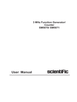
Block diagram on Figure 1 demonstrates input signal transformaon to series of me and frequency measurement data points.
First, input signal gets into input amplier. The generic role of input amplier circuits is matching the input to signal source, and
oponally: aenuate or amplify it, remove DC oset and/or lter out high-frequency noise.
Please note: There are several kinds of input amplier circuits (congurable input ampliers, prescalers, xed input ampliers), please
refer to 4.5 Input signal condioning/Input Ampliers chapter for more details about them.
Aer the input ampliers the signal is digized using one (inputs C, EA, ER) or 2 comparators (inputs A, B, D, E). It works the following
way: when the signal crosses the set trigger level, comparator generates a posive (in case of transion from below to above the
trigger level) or negave (in case of transion from above to below the trigger level) slope. Please refer to Figure 2 for an example.
Please note: For most measurement modes on inputs with 2 comparators, output of only one comparator is used for measuring the
signal from this input. However, there are measurement modes using both comparators implicitly:
• Rise/Fall Time and Slew Rate measurements use 2 comparators for geng Time Interval between lowest (10%) and highest
(90%) levels of the signal (see details in 5.4.3 Rise Time, Fall Time, Rise-Fall Time);
• Pulse width and Duty Cycle measurements use 2 comparators to produce pulses on posive and negave slope of a signal
and measure Time Interval between these;

20
• Frequency and Period Average use 2 comparators to implement implicit wide hysteresis targeted on improving noisy signals
measurements (see details in 5.1.1 Frequency/Period Average measurements chapter).
Second comparator can also be explicitly selected for measurement. E.g., Time Interval A, A2 will measure me interval between
signal level set by trigger level A and signal level set by trigger level A2 (can be useful for measuring characteriscs of mul-level
signals, e.g. TDR measurements – see 5.2.4 Measuring Time Interval between dierent trigger points of the same signal). It can also
be explicitly used as a source of start or stop arming.
Digized signals from physical inputs are just pulse trains which can be mulplexed to 4 internal measurement channels. Each
measurement channel starts with Wide Hysteresis block. Wide Hysteresis block just passes through the signal for most measurement
funcons except Frequency, Period Average, their Smart versions, TIE, and Frequency Rao for which implicit wide hysteresis is used
for beer noise tolerance (see 5.1.1 Frequency/Period Average measurements).
The resulng pulse train is then counted independently in each measurement channel. Measurement logic specic for each
measurement mode makes snapshots of channel’s pulse counter, mestamps it and adds channel number, forming series of so-called
raw results.
Raw results are further post-processed in calculaon block to form series of nal value-mestamps pairs. See Figure 2 for a visualized
example of signal processing happening inside CNT-104S.
Figure 1. Input signal to Time & Frequency measurement results transformaon
/