Page is loading ...

GPS-12, GPS-12R, GPS-12R/HS &
GPS-12RG
GPS & GLONASS / GPS
Frequency Standards
User’s Manual

II
4031 600 12001
Rev. 05 May 2017
© 2017 Pendulum Instruments / Altaria Services
.

Table of Contents
GENERAL INFORMATION ..........IV
1 Preface
Introduction .................1-2
2 Preparation for Use
Safety Instructions ............2-2
Introduction ......................2-2
Safety Precautions ................2-2
Unpacking ...................2-3
Unpacking Instructions .............2-3
Installation ..................2-4
Supply Voltage ...................2-4
Power Switch ....................2-4
Orientation and Cooling ............2-5
Fold-down Support ................2-5
Rackmount Adapter ...............2-5
Antenna Installation ...............2-7
Connecting to a PC ................2-7
Disposal of Hazardous Material . 2-8
3 Using the Controls
Front Panel ......................3-2
Rear Panel ......................3-3
Functional Description .............3-4
User Interface ....................3-4
4 GPS-12 Monitor
What is GPS-12 Monitor? ...........4-2
Requirements ....................4-2
Versions ........................4-2
Installation ......................4-2
Main Features ....................4-2
5 Performance Check
General Information ...............5-2
Preparations .....................5-2
Front Panel Controls ...............5-3
Front Panel Outputs ...............5-3
Rear Panel I/O ...................5-3
6 Preventive Maintenance
Calibration .......................6-2
Fan Replacement .................6-3
Battery Replacement ..............6-3
7 Specifications
Stability .........................7-2
Options .........................7-4
Ordering Information ...............7-8
8 Appendix
Antenna Installation ...............8-2
9 Index
10 Service
Sales and Service Offices .........10-II
III

GENERAL INFORMATION
Warranty
The Warranty Statement is part of the folder Important Information that is included with the
shipment.
Declaration of Conformity
The complete text with formal statements concerning product identification, manufacturer and
standards used for type testing is available on request.
Convention of Notation
Mostinformationinthismanualiscommontoallmodels. When the type number is used as a refer-
ence to any of them, the designation GPS-12X has been chosen for the sake of simplicity. Otherwise
the device is referred to with its proper type number, e.g. GPS-12 or GPS-12RG. Sometimes two
type numbers are combined, e.g. GPS-12(R) means GPS-12 and GPS-12R.
Figures illustrating the menu screens are generic. Where necessary, clarifying remarks or additional
figures have been included.
GNSS stands for Global Navigational Satellite System and is an acronym that refers to all satel-
lite-based navigational systems. In this manual it means either GPS or GLONASS and is, for exam-
ple, used in the graphical user interface whenever reference to a particular system is not necessary.
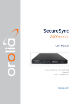
Front Panel Design
The picture illustrating the front panel in Chapter 3 shows the GPS-12, which is the latest addition
to this product family, now consisting of three models. During a transition period the other models
will be delivered with their present front panels. The two different designs are shown below for in-
formative reasons.
IV
ENTER
!
!
2.048 MHz OUT
±1.2V IN 75W
1 PPS OUTPUT
TTL
GPS-12 RUBIDIUM FREQUENCY STANDARDR
GPS-12R & GPS-12RG. GPS-12

Chapter 1
Preface

Introduction
Cesium-controlled
Frequency via Satellites
The GPS-controlled frequency standards
GPS-12(R) and the GLONASS/GPS-con-
trolled frequency standard GPS-12RG deliver a
precision frequency and time reference every-
where in the world. They gain their long-term
frequency stability from Cesium standards in
the navigation satellite systems GPS and
GLONASS. They are also designed to provide
very high short-term stability and are cost-effi-
cient and extremely accurate frequency
standards.
These reference sources are very suitable as fre-
quency standards in the telecommunication and
electronics industry. They fit both as stationary
frequency references - for instance in test sys-
tems and as local references in the design depart-
ment - and as portable, highly accurate reference
sources for field use.
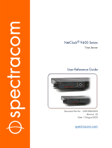
These instruments are off-air frequency stan-
dards with an internal architecture according to
Figure 1-1. They have one antenna input and a
number of optional frequency outputs.
There is also an option for disciplining with an
external 1 pps source, e.g. an in-house cesium
standard.
Optional I/O Boards
The GPS-12X comes as standard with two
2.048/1.544 MHz square wave outputs and one
1 pps pulse output with approx. 10 µs duration.
TheGPS-12RGhasalso3x10MHzand
1x5MHzoutputs.SeeOption70Bbelow.
There are six options to choose from, options
70B, 71B, 72B, 73B, 74B and 79/01. All but the
79/01 allow for four extra frequency outputs to
be mounted. Any combination of none, one or
two of these units is possible. Only one
79/01can be mounted.
Option70Bgives3x10MHzand1x5MHz
sine wave outputs, 1 VRMS in 50 W.The
GPS-12RG is as standard equipped with one
such option.
Option 71B gives four sine wave outputs,
1VRMS in 50 W, of resp. 10 MHz, 5 MHz, 1
MHz and 0.1 MHz.
Option 72B gives 2 x 2.048 MHz clock outputs,
±1.2 V square wave in 75 W,plus
2 x 2.048 Mbps data outputs (G.703:10), for
telecommunication testing and clock synchro-
nization.
Option 73B gives 4 x 13 MHz square wave out-
puts with TTL levels in 50 W.
Option 74B gives 2 x 1.544 MHz plus
2 x 1.544 Mbps outputs for SONET
applications.
Option 79/01 gives 2 x 10 MHz sine
wave outputs, 1 VRMS in 50 W,plus
1 x 1 pps output, TTL levels in 50 W,
plus 1 x 1 pps disciplining input, TTL
levels.
1-2
Preface
Satellite
Receiver
Refererence Ou
t
Phase
Comparator
Local
Oscillator
(VCO)
Figure 1-1 Simplified block diagram of the GPS-12X.

Reference Oscillators
The GPS-12 is equipped with an oven-con-
trolled crystal oscillator (OCXO), the GPS-12R
has a standard rubidium oscillator, and the
GPS-12R/HS has a high-stability, low phase
noise rubidium oscillator. The GPS-12RG is
also equipped with the latter oscillator.
Two Operating Modes
The disciplined mode is the default mode. It
eliminates long-term frequency drift, also
called aging. As long as there is a valid satellite
signal, the local rubidium oscillator is continu-
ously adjusted to minimize the deviation from
the satellite-derived reference signal.
The hold-over mode is entered either automati-
cally, if the satellite contact is lost, or manually.
The automatic adjustment is replaced by the
normal aging characteristics of the rubidium
oscillator.
The manual hold-over mode is mainly intended
for the hopefully rare occasions when the satel-
lite contact is sporadic, causing unacceptable
mode switching interference.
Portability
BymeansofOption78orOption78/HS,anin
-
ternal rechargeable battery unit, it is possible to
maintain stability during transportation, as the
internal reference oscillator is continuously
powered.
Field use without access to AC line power is
also practicable.
Option 78/HS has the additional feature of ac-
ceptinganexternal12V
DC supply. Thus it is
possible to realize a true uninterruptible power
supply (UPS), as the DC source and the AC
source can be applied simultaneously. The AC
source takes precedence, as long as it is present,
and so does the external DC supply over the in-
ternal battery, which is kept charged by one of
the external sources.
In case of a power line failure you will benefit
from double security, if you utilize an external
DC source in addition to the AC supply.
Stationary Use
Option 77 makes it possible to apply -48 VDC
as an alternative to the standard AC line volt-
age, thus allowing permanent use as local fre-
quency standard in telephone exchange sta-
tions. AC line voltage and -48 VDC can be ap-
plied at the same time in order to realize a true
uninterruptible power supply (UPS).
Overall Accuracy
The cesium standards of the satellites are con-
trolled by primary frequency standards like the
US Naval Observatory, and ultimately to all na-
tional standards (e.g. NIST, NPL, PTB, SP
etc.).
1-3
Preface

This page is intentionally left blank.
1-4
Preface

Chapter 2
Preparation for Use

Safety Instructions
Introduction
Read this chapter carefully before you install
and use the instrument.
This instrument has been designed and tested
for Measurement Category I, Pollution Degree
2, in accordance with EN/IEC 61010-1:2001
and CAN/CSA-C22.2 No. 61010-1-04 (includ-
ing approval). It has been supplied in a safe
condition. The user of this instrument must
have sufficient knowledge of it. This knowl-
edge can be gained by thoroughly studying this
manual, especially the sections on Safety Pre-
cautions and Installation in this chapter.
This instrument is designed to be used by
trained personnel only. Removal of the cover
forrepairorrack-mountingoftheinstrument
must be done by qualified personnel who are
aware of the hazards involved. There are no
user-serviceable parts inside the instrument.
Safety Precautions
All equipment that can be connected to line
power is a potential danger to life. Handling re-
strictions imposed on such equipment should
be observed.
To ensure the correct and safe operation of this
instrument, it is essential that you follow gener-
ally accepted safety procedures in addition to
the safety precautions specified in this manual.
The warranty commitments are rendered
void if unauthorized access to the interior of
the instrument has taken place during the
given warranty period.
Caution and Warning
Statements
CAUTION: Shows where incorrect
procedures can cause damage to,
or destruction of equipment or
other property.
WARNING: Shows a potential danger
that requires correct procedures or
practices to prevent personal in-
jury.
Symbols
Shows where the protective ground
terminal is connected inside the instru-
ment. Never remove or loosen this
screw.
This symbol is used for identifying the
functional ground of an I/O signal. It is
always connected to the instrument
chassis.
Indicates that the operator should con-
sult the manual.
If in Doubt about Safety
Whenever you suspect that it is unsafe to use
the instrument, you must make it inoperative by
doing as follows:
–Disconnect the line cord.
–Clearly mark the instrument to prevent its
further operation.
–Inform your local Pendulum Service Center.
For example, the instrument is likely to be un-
safe if it is visibly damaged.
2-2 Introduction
Preparation for Use

Unpacking
Unpacking
Instructions
Check that the shipment is complete and that no
damage has occurred during transportation. If
the contents are incomplete or damaged, file a
claim with the carrier immediately. Also notify
your local Pendulum sales or service office in
case repair or replacement may be required.
Check List
The shipment should contain the following:
–The frequency standard.
–A line cord.
–A CD with PDF manuals for Pendulum
products, e.g. this manual.
–If you ordered one or two of the output
options (70B, 71B, 72B, 73B, 74B), or the
disciplining option (79/01), or one of the
DC supply options (77, 78, 78/HS), they
should already be installed. See “Identifi-
cation” below.
Note 1: The GPS-12R/HS and the
GPS-12RG are as standard
equipped with one Option 70B.
–If you ordered one of the DC supply op-
tions (77, 78/HS), a three-pole power
D-sub socket connector is included that
mates with the corresponding rear panel
pin connector. It is intended for making a
wire harness suitable for linking the instru-
ment to an external DC power source.
–Other options you ordered, e.g. antenna
(option 01), antenna cable (option 02),
rack mount kit (option 22) or carrying
case (option 27/27H) are shipped in sepa-
rate boxes.
–Certificate of Calibration.
Identification
Options installed inside the cover are identified
on the rear panel according to the list below. Up
to two output boards in any combination can be
fitted at the same time. The combined I/O board
Option 79/01 is an exception. Only one such
board can be fitted. However, it can be com-
bined with any other output board.
Option 70B: 4 BNC-connectors mounted in the
area designated.
Option 71B: 4 BNC-connectors mounted in the
area designated.
Option 72B: 4 BNC-connectors mounted in the
area designated.
Option 73B: 4 BNC-connectors mounted in the
area designated.
Option 74B: 4 BNC-connectors mounted in the
area designated.
Option 77: -48 VDC power supply & rear panel
power D-sub connector.
Option 78: Internal 16 VDC rechargeable bat-
tery for GPS-12(R)
Option 78/HS: Internal 16 VDC rechargeable
battery & rear panel power D-sub connector for
ext. 12 VDC source. Intended for GPS-12R/HS
and GPS-12RG.
Option 79/01: 4 BNC-connectors mounted in
the area designated.
2-3 Unpacking Instructions
Preparation for Use

Installation
Supply Voltage
Setting
The GPS-12X frequency standard can be con-
nected to any AC supply with a voltage rating
of 90 to 265 Vrms, 45 to 440 Hz. The frequency
standard automatically adjusts itself to the in-
put line voltage.
Depending on option chosen, the unit can also
be supplied by external DC sources, -48 V or
+12 V.
Fuse
The secondary supply voltages are electroni-
cally protected against overload or short cir-
cuit. The primary line voltage side is protected
by a fuse located on the power supply unit. The
fuse rating covers the full voltage range. Con-
sequently there is no need for the user to re-
place the fuse under any operating conditions,
nor is it accessible from the outside.
CAUTION: If this fuse is blown, it is
likely that the power supply is
badly damaged. do not replace the
fuse. Send the frequency standard
to the local Pendulum Service Cen-
ter.
Grounding
Grounding faults in the line voltage
supply will make any instrument con-
nected to it dangerous. Before con-
necting any unit to the power line, you must
make sure that the protective ground functions
correctly. Only then can a unit be connected to
the power line and only by using a three-wire
line cord. No other method of grounding is per-
mitted. Extension cords must always have a
protective ground conductor.
WARNING: If a unit is moved from a
cold to a warm environment, con-
densation may cause a shock
hazard. Ensure, therefore, that the
grounding requirements are strictly
met.
WARNING: Never interrupt the
grounding cord. Any interruption
of the protective ground connec-
tion inside or outside the
instrument or disconnection of the
protective ground terminal is likely
to make the instrument dangerous.
Power Switch
This instrument is equipped with a secondary
power switch. It disconnects the main
power-consuming circuits on the secondary
side of the power supply but leaves the rubid-
ium oscillator active in order to retain its
long-term characteristics. Line voltage is al-
ways present on the primary side.
WARNING: Always consider the in-
strument active as soon as it is
connected to the primary AC
power source with a power cord.
2-4 Supply Voltage
Preparation for Use

Orientation and
Cooling
The frequency standard can be operated in any
position desired. Make sure the air flow
through the ventilation slots are not obstructed.
Leave 50 mm (2 in) of space around the
instrument.
CAUTION: Never cover the ventila-
tion slots at the right or left side. If
the slots are covered, the fre-
quency standard will overheat.
Fan Control
The speed-controlled fan is used for adjusting
the temperature inside the frequency standard
to compensate for variations in ambient tem-
perature.
Fold-down Support
For bench-top use, a fold-down support is
available for use underneath the frequency
standard. This support can also be used as a
handle to carry the instrument.
Rackmount
Adapter
If you have ordered a 19 inch rack mount kit for
your instrument, it has to be assembled after de-
livery of the instrument. The rack mount kit
consists of the following:
2 brackets, (short, left; long, right)
4screws,M5x8
4screws,M6x8
WARNING: When you remove the
cover you will expose live parts
and accessible terminals which
can cause death.
2-5 Orientation and Cooling
Preparation for Use
Figure 2-1 Air flow through the GPS-12X.
Figure 2-2 Fold-down support for comfort-
able bench-top use.
Figure 2-3 Dimensions for rackmounting
hardware.

WARNING: Capacitors inside the in-
strument can hold their charge
even if the instrument has been
separated from all voltage sources.
Assembling the Rackmount
Kit
–Make sure the power cord is disconnected
from the instrument.
–Turn the instrument upside down.
See Figure 2-4.
–Undo the two screws (A) and remove
them from the cover.
–Remove the rear feet by undoing the two
screws (B).
–Remove the four decorative plugs (C) that
cover the screw holes on the right and left
side of the front panel.
–Grip the front panel and gently push at the
rear.
–Pull the instrument out of the cover.
–Remove the four feet from the cover.
Use a screwdriver as shown in the following il-
lustration or a pair of pliers to remove the
springs holding each foot, then push out the
feet.
–Push the instrument back into the cover.
See Figure 2-4.
–Mount the two rear feet with the screws
(B) to the rear panel.
–Put the two screws (A) back.
–Fasten the brackets at the left and right
side with the screws included as illustrated
in Figure 2-6.
–Fasten the instrument in the rack via
screws in the four rack-mounting holes
The long bracket has an opening so that cables
for Input A, B, and C can be routed inside the
rack.
nReversing the Rackmount Kit
The instrument may also be mounted to the
right in the rack. To do so, swap the position of
the two brackets.
2-6 Rackmount Adapter
Preparation for Use
Figure 2-4 Remove the screws and push
the frequency standard out of
the cover.
Figure 2-5 Removing the feet from the
cover.
Figure 2-6 Fitting the rackmount brackets
on the counter.

Antenna
Installation
The antenna (option 01), is intended for out-
door mounting on a wall or preferably on a
roof. The more free sky that is visible from the
antenna’s position, the better the satellite con-
tact. There is an antenna mounting kit (Option
01/50) available for this purpose.
The antenna cable is a 20 m (Option 02) or
50 m (Option 02/50), or 130 m (Option 02/130)
high quality RG213 cable that connects at one
end to the antenna and at the other end to the
rear panel of the frequency standard. For instal-
lation details and instructions on connecting
other antennas/cables than those supplied by
Pendulum, please consult the Appendix in this
manual.
ConnectingtoaPC
A PC can be connected to the USB port at the
rear of the instrument for firmware download
or communication with the optional SW pack-
age GPS-12 Monitor. A suitable cable should
have one USB-A connector (for the PC) and
one USB-B connector -for the GPS-12X.
The procedure is described in the service man-
ual, as only trained personnel should do FW up-
grades. Erroneous handling of the instrument
before and during the download may damage
the memory contents and prohibit the comple-
tion of the loading process.
2-7 Antenna Installation
Preparation for Use

Disposal of Hazardous Material
The basic instrument and all optional units ex-
cept Option 78 and Option 78/HS have no bat-
teries or other parts containing hazardous
amounts of substances that require special at-
tention or handling instructions.
Option 78 and Option 78/HS contain a re-
chargeable NiMH battery pack that serves the
purpose of providing uninterruptible power to
the instrument. As all batteries, it has a finite
lifetime. Although NiMH-based cells are by far
less detrimental to the environment than their
NiCd-based predecessors, we strongly recom-
mend to dispose of them by controlled recy-
cling.
CAUTION: Make sure the battery
pack is recycled according to local
regulations.
2-8 Connecting to a PC
Preparation for Use

Chapter 3
Using the Controls

Front Panel
3-2 Front Panel
LCD display with backlight forming the
User Interface (UI) together with the
CURSOR and ENTER keys to the right.
The default messages inform the user about
Control Mode (Disciplined or Hold-over),
Satellite Status, Alarm, Power Source, User
Options and Time/Position.
POWER ON / STANDBY
key. A secondary power
switch that ligths up the red
LED above the key in standby
mode.
The CURSOR keys (with arrow symbols)
are used for moving the cursor, marked by
text inversion, around the menus on the
display. By pressing the ENTER key you
either confirm a choice or enter a submenu.
Back one step by pressing the LEFT AR-
ROW key.
BNC Reference Output Connectors
2 x 2.048 MHz* + 1 x 1 pps / 10 MHz** or
2x1.544MHz*+1x1pps/10MHz**
* The choice is made in the User Options
submenu.
** Only newer HW versions have the
10 MHz alternative. The choice is made in
the User Options submenu.
Optional outputs can be found on the rear
panel.

Rear Panel
3-3 Rear Panel
Using the Controls
! !
! ! !
!
!
!
!
2.048 MHz OUT
2.048 MHz OUT
2.048 MHz OUT
2.048 MHz OUT
2.048 Mbps OUT
2.048 Mbps OUT
2.048 Mbps OUT
2.048 Mbps OUT
-48VDC
GPS ANTENNA IN
:
USB
;
191125
ALARM
GND
+12VDC
Antenna cable input
(N-contact)
Power input
90-265 V,
45-440 Hz
USB port for firm-
ware download
from PC
Optional Outputs
Option 70B: sine wave
3x10MHz+1x5MHz
Option 71B: sine wave
1x10MHz+1x5MHz+1x1MHz+
1x0.1MHz
Option 72B: square wave
2 x 2.048 MHz +2 x 2.048 Mbps
Option 73B: square wave 4 x 13 MHz
Option 74B: square wave
2 x 1.544 MHz + 2 x 1.544 Mbps
Option 79/01: 1 x 1 pps disciplining input
+ 1 x 1 pps output + 2 x 10 MHz
low-noise outputs
Two relay-con-
trolled alarm
loops, one for
urgent and one
for non-urgent
situations.
See page 3-6
for pin config-
uration.
Optional
external DC
power inputs
Fan with automatic
speed control

Functional
Description
The GPS-12X series of frequency standards is
continuously disciplined by control signals
from satellites belonging to the GPS
[GPS-12(R)] or the GLONASS/GPS
[GPS-12RG] navigation satellite systems. The
signals have very low long-term uncertainty
(5*10-13 per 24h), and are traceable to different
national standards for time and frequency at,
for instance, the National Institute of Standards
and Technology (NIST) via the US Naval Of-
fice (USNO). The GPS-12X contains a satellite
receiver module, generating a stable 1 pps sig-
nal, plus a local voltage-controlled rubidium or
crystal oscillator (OCXO) and a high resolution
measurement kernel that is continuously
phase-comparing the received satellite signal
and the local oscillator. This means that the lo-
cal oscillator is continuously monitored and ad-
justed.
The GPS-12X can operate in two different
modes. Either the local oscillator is free-run-
ning with a frequency offset that increases with
time, due to aging, or the results of the phase
comparisons are used for adjusting the local os-
cillator, thereby compensating for aging. These
two modes are called:
–Hold-over mode (free-running local oscil-
lator)
–Disciplined mode (monitored and adjusted
local oscillators)
Disciplined mode is the default mode.
Hold-over mode is automatically entered when
the disciplining fails for some reason (e.g. loss
of satellite contact). Hold-over mode can also
be forced via the User Interface (UI). When the
satellite contact is lost, the GPS-12X can not be
continuously controlled (intercompared with
the satellite reference clocks in real time) and
reverts temporarily to hold-over mode specifi-
cations.
User Interface
General Principles
The UI is straightforward. All interaction be-
tween operator and instrument takes place by
navigating a cursor (marked by text inversion)
on the LCD through a set of text-based menus.
The navigating tools are just four arrow keys,
UP (p), DOWN (q), LEFT (t),
RIGHT (u), and one ENTER key. The differ-
ent menus are described in the fol-
lowing paragraphs.
Default Menu
This is the menu entered at start-up
and shows the current instrument sta-
tus. Here RB-osc is selected, and to
the right you can find one of the fol-
lowing short informative texts:
•Warming up
•Unlocked
•Hold-over
3-4 Functional Description
Using the Controls
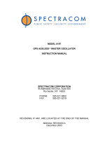
Satellite
Receiver 2.048 MHz Output
s
To PC (USB)
PLL-Controlled
Frequency Reference Oscillator
(Rubidium or OCXO)
1 PPS
1 PPS Output
Output Opt.
Other Frequencies
Output Opt.
User Interface (UI)
(Front Panel Keyboard & Display)
Microprocessor
&
Memory
I/O Option
1 PPS Input
1 PPS Output
10 MHz Output
Figure 3-1. The internal high-stability oscillator of the
GPS-12X is continuously compared with
and controlled by the satellite receiver.
/