Page is loading ...

D*AP8 MAP Edition
Monitoring Audio Processor
Manual

DAP8-MAP_manual_EN_180724.doc
D*AP8 MAP
Hardware features
•
D*AP8 unit 1RU / 19" generic compact 8 channel processing unit
•
X*AP RM
1
optional 1RU detachable remote panel
•
Dolby decoder optional built in Dolby D/D+/E decoder incl. metadata emulation
• Dolby encoder optional built in Dolby D/D+/AAC/HE-AAC or Dolby E encoder
• Dolby metadata I/O two 9-pin D-Sub connectors (RS485)
•
4x AES (BNC) I/O + SRC on board AES I/Os with relay bypass and (selectable) SRC per input
• Two interface slots expansion slots for optional I/O boards:
3-G/HD/SD-SDI, MADI, DANTE, 4x AES I/O, 4Ch Analog I/O,
8Ch Analog (speaker) Out
• RJ45 network connector 100BaseT full duplex Ethernet interface
• USB connector built in USB < > serial adapter to access the service port
• 8x GPI/O balanced inputs and relay contacts on a 25pin Sub-D
•
Aux power supply isolated 5V supply for external GPI/O wiring
•
External sync IN BNC input (Word Clock, AES, Black Burst, Tri-Level)
•
Sync OUT BNC Word Clock output
Software features
•
TP limiter Junger Audio true peak limiter control algorithm for speaker protection
• Speaker alignment delay, level and frequency response compensation, speaker identification
• Bas management for subwoofer and satellite speaker installations
• Solo- / In Place / Defeat individual speaker control
• Mute / DIM mutes / dims all speaker channels
•
Delay, gain, polarity for input signal correction
• Downmix separate downmix circuits for program and AUX feed
• Dolby metadata generator generates RDD6 compliant metadata
• Dolby metadata emulation shows the effect of metadata for decoded Dolby (E, D, D-D plus)
or PCM signals
• Loudness measurement ITUBS.1770-1/ -2/ -3, EBU R128
• Loudness / level display X*AP RM
1
display, J*AM Junger Application Manager
•
SNMP agent SNMP v1 get (no set) and configurable traps (see MAP-MIB)
•
Remote control X*AP RM1 remote panel, l-s-b EmBER+ protocol
and legacy GPI/Os
operating manual

D*AP8 MAP
1
Content
page
Introduction ………………………………………………………………………………………… 3
Hardware concept .......……………………………………………………………………………. 4
D*AP8 unit front panel view ………………………………………………………………………. 4
X*AP RM1 front panel view ……………………………………………………………………… 4
D*AP8 unit rear view ……………………………………………………………………………… 5
Block diagram ………………………………………………………………………………………. 6
Control, Operating & Event concept ……………………………………………………………… 7
Getting started – IP setup in general …………………………………………………………….. 8
Getting started – IP setup – via console interface ……………………................................. 8
Getting started – IP setup – via web browser …………………………………………………. 9
Getting started – basic X*AP RM1 remote panel operation …………………………………… 10
Operating – menu structure of the X*AP remote panel – operating display ………………. 10
Operating – menu structure of the X*AP remote panel – menu tree ………………………… 13
Setup GUI – connecting with the D*AP8 unit – AUDIO PROCESSOR – Overview ………. 14
Setup GUI – SYSTEM – System Status …………………………………………………………. 15
Setup GUI – SYSTEM – Overview ……………………………………………………………….. 16
Setup GUI – SYSTEM – Admin ………………………………………………………………….. 17
Setup GUI – SYSTEM – Setup …………………………………………………………………… 19
Setup GUI – SYSTEM – Remote Access – X*AP Remote …………………………………… 21
Setup GUI – SYSTEM – The preset concept in detail…………………………………………. 22
Setup GUI – SYSTEM – SNMP …………………………………………………………………… 24
Setup GUI – SYSTEM – Backup / Restore ……………………………………………………. 24
Setup GUI – SYSTEM – Firmware Update …………………………………………………….. 25
Setup GUI – SYSTEM – Reboot …………………………………………………………………. 26
Setup GUI – INTERFACES – AES I/O …………………………………………………………… 27
Setup GUI – INTERFACES – SDI I/O Interface – Overview ……………………………........ 28
Setup GUI – INTERFACES – SDI I/O Interface – Local Routing ………………………........ 29
Setup GUI – INTERFACES – SDI I/O Interface – Setup ………………................................. 30
Setup GUI – INTERFACES – SDI I/O Interface – De-Embedder …………………………..... 30
Setup GUI – INTERFACES – SDI I/O Interface – Embedder …………………………............ 31
Setup GUI – INTERFACES – MADI Interface – Status / Setup …………………………........ 32
Setup GUI – INTERFACES – MADI Interface – Local Routing …………………………........ 33
Setup GUI – INTERFACES – Dante I/O Interface – Status ………………………….............. 34
Setup GUI – INTERFACES – Dante I/O Interface – Inputs ………………………….............. 36
Setup GUI – INTERFACES – Dante I/O Interface – Ouputs …………………………............ 38
Setup GUI – INTERFACES – Dante I/O Interface – Network ………………………….......... 38
Setup GUI – INTERFACES – 8 Ch Analog Interface …………………………...................... 40
Setup GUI – INTERFACES – 4 Ch Analog I/O Interface …………………………................ 40
Setup GUI – INTERFACES – AES Interface – Status / Setup ……………………................ 41
Setup GUI – ROUTING ……………………………………………………………………………. 42
Setup GUI – DOLBY PROCESSING in general ……………………………………………….. 44
Setup GUI – DOLBY PROCESSING – Decoder / Emulation ……………………………….. 44
Setup GUI – DOLBY PROCESSING – Decoder/Emulation – Decoder …………………….. 46
Setup GUI – DOLBY PROCESSING – Decoder/Emulation – Decoder/Emulation ……….. 47
Setup GUI – DOLBY PROCESSING – Metadata – Routing …………………………………. 49
Setup GUI – DOLBY PROCESSING – Metadata – Generator Setup ………………………. 49
Setup GUI – DOLBY PROCESSING – Metadata – Program x ………………………………. 50
Setup GUI – DOLBY PROCESSING – optional Dolby E Encoder – Encoder A …………… 52
Setup GUI – DOLBY PROCESSING – optional consumer format Encoder – Encoder B … 52
Setup GUI – AUDIO PROCESSOR – Overview ……………………………………………….. 54
Setup GUI – AUDIO PROCESSOR – Setup ……………………………………………………. 55
Setup GUI – AUDIO PROCESSOR – Input .………………………………….......................... 56
Setup GUI – AUDIO PROCESSOR
– Downmix ……………………………………………….. 57
Setup GUI – AUDIO PROCESSOR
– Solo/Mute ………………………………………………. 58
Setup GUI – AUDIO PROCESSOR – Volume …………………………………………………. 59
Setup GUI – AUDIO PROCESSOR – Matrix …………………………………………………… 60
Setup GUI – AUDIO PROCESSOR – Output – Bass Management ………………………… 61
Setup GUI – AUDIO PROCESSOR – Output – Equalizer …………………………................ 63
Setup GUI – AUDIO PROCESSOR – Output – Speaker ……………………………………… 64

D*AP8 MAP
2
Content
page
Setup GUI – MEASURMENT ……………………………………………………………………… 66
Setup GUI – MEASURMENT – Setup …………………………………………………………… 66
Setup GUI – MEASURMENT – Loudness – Main ……………………………………………… 65
Setup GUI – MEASURMENT – Loudness – Log Ports ………………………………………... 67
Setup GUI – MEASURMENT – Alarms – Main …………………………………………………. 68
Setup GUI – MEASURMENT – Alarms – Log Ports ………………………………………....... 69
Setup GUI – MEASURMENT – Log Port Routing …………………………………………….. 69
Setup GUI – EVENTS – Overview ………………………………………………………………. 70
Setup GUI – EVENTS – Triggers – Sources – Remote Hotkeys ……………………………. 71
Setup GUI – EVENTS – Triggers – Sources – Network ……………………………………… 71
Setup GUI – EVENTS – Triggers – Sources – Parameters ………………………………….. 73
Setup GUI – EVENTS – Triggers – Configuration – Trigger Equation ……………………... 73
Setup GUI – EVENTS – Events – Preset Events ……………………………………………… 74
Setup GUI – EVENTS – Events – Parameter Events …………………………………………. 75
Setup GUI – EVENTS – Events – Measurement Events …………………………………….. 76
Setup GUI – EVENTS – Events – I/O Events ………………………………………………….. 76
Setup GUI – EVENTS – Actions – Event Actions …………………………………………….. 77
Setup GUI – EVENTS – Actions – Event Actions – Factory Defaults ………………………. 78
Setup GUI – accessDP …………………………………………………………………………….. 81
Technical Data – 8 Channel Surround Monitoring Audio Processor [D*AP8 MAP EDITION] 84
Technical Data – Option Board SDI I/O (3G/HD/SD) [O_DAP_SDI_a] ……………………… 85
Technical Data – Option Board 8 Ch Analog Out [O_DAP_8DA_a] …………………………. 86
Technical Data – Option Board 4 Ch Analog I/O [O_DAP_ADDA_a] ……………………….. 87
Technical Data – Option Board AES/EBU I/O [O_DAP_AES_a] …………………………….. 88
Technical Data – Option Board MADI I/O, BNC [O_DAP_MB_a] ……………………………. 88
Technical Data – Option Board MADI I/O, Optical [O_DAP_MO_MM_a] …………………… 89
Technical Data – Option Board MADI I/O, Optical [O_DAP_MO_SM_a] …………………… 89
Technical Data – Option Board Audio-over-IP DANTE™ [O_DAP_DANTE_a] ……………. 90
Technical Data – Rear Connectors – pin assignment ………………………………………... 90
Technical Data – Optional Interface Modules – pin assignment ……………………………. 91
Technical Data – GPI wiring ……………………………………………………………………… 92
Safety Information …..…………………………………………………………………………… 93
Warranty …………………………………………………………………………………………….. 93

D*AP8 MAP
3
Introduction
The MAP is a monitoring processor, assembled from the generic digital audio processor D*AP8 that runs the
MAP firmware and an optional X*AP RM
1
remote panel. The bundle is designed to ease the quality
monitoring of surround and stereo signals for producers, editorial staff and engineers especially when it
comes to Dolby encoded signals.
For level and loudness measurement and logging applications the D*AP8 unit may be used as a
measurement box that sits close to the signal sources while measurement data will be streamed over the
network to a PC for live display and/or storing of such data.
A sophisticated audio processor at the heart of the MAP works. It renders the monitoring facility, audio
delays, speaker bass management as well as level and loudness measurements.
A Dolby metadata generator is provided for emulation of the influence of metadata on PCM audio signals
directly from the monitoring section of a mixing console. For live and post production it allows you to hear how
the metadata will influence the listening experience on the customers side without introduction of an encoder
/ decoder. The emulation part incorporates a Dolby stream decoder. An optional Dolby consumer format or
a Dolby-E encoder can be added to the device.
The four AES3id I/Os on the motherboard may be complemented by a variety of interface modules that can
be installed as an option into the D*AP8 interface slots. For the MAP standalone application normally one slot
will be fitted with the 8 channel analog speaker interface card.
Comprehensive routing set-ups allow almost every signal flow from hardware inputs, from and to optional
Dolby decoder / encoder, from the audio processor itself to the speakers, to hardware outputs as well as the
metadata I/Os, the metadata generator and the metadata emulator.
Routing paths, the enabling and disabling of audio processing blocks and the setting of processing
parameters can be pre-configured by individual presets dedicated to each function block. The content of the
presets can be displayed and edited off-line while the device is in use. These presets may either be recalled
on demand by the operator via the GUI, the X*AP RM
1
remote panel hot keys or external systems, but may
also be part of complex scenarios defined by the administrator and automatically executed by the event
manager of the device or by operator intervention.
The MAP provides a web based setup GUI and can be controlled by an X*AP RM
1
remote panel that
displays status and metering information and allows user intervention.
Junger Audios application manager J*AM is available as an add on and can be attached with a few simple
clicks to the MAP so that users can log loudness data as well as display it as a live plot on a PC screen in
real time or simply display level bar graphs. For production / post-production needs a built-in LTC reader will
be available in the near future. So loudness logging may then be performed in regard to relative time as well
as to time of day.
Completing the feature set of the MAP is the availability of an SNMP agent, which provides traps and status
polling.
As with most advanced tools, the MAP can be driven in a variety of ways, depending on requirements and
ideas of the user. These can range from simple and straightforward to quite complex set ups.
Although this manual explains the functions and general operation of the MAP, it does not give detailed
scenarios because the operational needs of today’s broadcasters vary so widely between organizations and
their work flows and cover so many different parameters – from ingest to studio operation, from master
control rooms to play-out, or even rebroadcast applications.
Junger Audio is more than happy to discuss your particular requirements with you and to convey your ideas
and solutions to other users of the Junger Audio Processors community.

D*AP8 MAP
4
Hardware concept
The MAP consists of a D*AP8 unit with MAP firmware that carries all relevant connectors and an optional
X*AP RM
1
remote panel both in 19" 1RU format.
D*AP8 unit front panel view
The front panel of the D*AP8 MAP has a 3 line status display and two hidden touch buttons ~ 2.5cm left of
the display. Button 1 = Home will switch back to the power up display no matter which display level you are
in. Button 2 controls the multi level display:
Level 1 Power up display [Device type, firmware version]
Level 2 Status [OK / Error] / Device Name / IP address
Level 3 IN peak meter (10x)
Level 4 OUT peak meter (10x)
The total number of display levels depends on the number of programs. For 5.1 + 2 mode (2 programs) we
will have 4 more levels while for 4 x 2 (4 programs) we will have 8 more levels:
Level 5 - 8 Program 1 - 4 Out - short term loudness
Level 9 - 12 Program 1 - 4 Out - integrated loudness and integration time
The measures of the loudness displays depend on the setup of the respective loudness mode
(see AUDIO PROCESSOR > SETUP > Loudness Mode).
Display background Green = hardware status OK
color Red = hardware status ERROR
X*AP RM
1
front panel view
The X*AP RM
1
remote panel is powered by POE (Power Over Ethernet) or external wall plug PS and
designed to control multiple D*AP8 units one at a time. For details of operation see extra manual
"XAP_manual_EN_140328.pdf" or later.

D*AP8 MAP
5
D*AP8 unit rear view
For fail safe operation the D*AP8 unit provides two independent power supplies. These power supplies
operate in load balance. The status of both PS are displayed on the D*AP8 unit front panel as well as on
the X*AP RM
1
remote panel.
STATUS LED indicates the status of the device controller. It becomes green at the end of
a successful boot process
INIT / RESET pressing the INIT / RESET button briefly will warm start the device controller.
Holding down the button and release it until the STATUS LED did flash:
3 times initiates a cold start
4 times the device will be cold started with the previous firmware image
5 times will initialize the D*AP8 unit to factory default and will be cold started
Be patient it takes about 20 sec. Until the flashing starts.
LAN RJ45 socket for Ethernet connection to a LAN
USB USB 2.0 type B socket to connect the built in USB >> serial converter with an
external PC to reach the console interface of the system controller
ISO-PWR LED indicates that the isolated 5V power supply for GPI/O application is active
GPI/O 25pin Sub-D female connector to interface with the 8 optical isolated general
purpose inputs and with the 8 switch over relay general purpose outputs
Interface 1 slot to mount one of the optional interface boards (SDI, AES, analog)
Interface 2 slot to mount one of the optional interface boards (SDI, AES, analog)
METADATA IN 9pin Sub-D female connector to receive and send Dolby® serial metadata
METADATA OUT 9pin Sub-D male connector to send Dolby® serial metadata
LTC IN LTC timecode input not activated jet
SYNC IN 75Ohm BNC connector to connect with external sync sources
WCKL-OUT 75Ohm BNC connector to synchronize external devices to the D*AP8 unit
internal word clock
AES IN 1/2 – 7/8 AES3id inputs
AES OUT 1/2 – 7/8 AES3id outputs

D*AP8 MAP
6
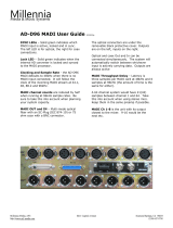
Block diagram
The above schematic shows the principal blocks of a fully loaded MAP.
The core of the unit is the audio processor. It has 2x 8 inputs, 8 outputs and a 2ch downmix AUX output.
It controls the speaker setup and settings during the monitoring session.
The device also provides the measurement data (true peak, level, loudness) for external applications like the
J*AM (Junger Application Manager) for logging and/or display on a PC or tablett screen via the Log Ports.
The Dolby Metadata Emulation is a hardware option that comes with the Dolby decoder. It is a functional
block that may be connected to the respective audio input / output signals via the device router.
Same applies for the metadata pathes that must be routed separately.
A Dolby encoder may be fitted as an option as well to provide encoded output to save the customers rack
space and installation cost.
On the motherboard you will find 4x AES3id I/Os which are bridged by relays in case of a power failure.
This hardware fail-over may be disabled for each I/O pair by internal jumpers.
Two interface slots which may carry option boards allow for extremely flexible interfacing of the MAP.
One of the interface slots will normally be equipped with an 8-channel analog line output board for direct
speaker connection while the other willl normally hold a 3G/HD/SD-SDI option board for TV production
applications.
For comprehensive metadata processing the unit has serial metadata I/O connectors. All metadata functions
are centralized in a metadata generator. Furthermore you will have the possibility to emulate the influence of
Dolby metadata on the audio signals for stereo or surround signals and down mixes, without the need to
involve an encoder and decoder.
The sync circuit can deal with all formats to integrate the device into digital facilities. Other devices may be
synchronized via the word clock output of the MAP. The frame reference for D-E encoding, may be shifted to
align the D-E guard band.
The MAP has 8 balanced GPIs and 8 SSR closure GPOs. This enables the user to simply recall presets or
call events, change device configurations and report general status information.

D*AP8 MAP
7
Control concept
The communication between the X*AP RM
1
remote panel, the D*AP8 unit, setup and operating tools, is
based on TCP/IP over Ethernet.
The setup GUI utilizes web technology. At the time of editing this manual the functionality of the web GUI is
optimized for Firefox 30.x and higher.
The setup GUI can be complemented by other application programs running on MS Windows® XP, W7
like the J.A. Application Manager J*AM.
An SNMP agent is also available on the device and may be explored via a SNMP monitoring system.
For 3
rd
party remote control Junger Audio highly recommends using the l-s-b EmBER+ protocol which is
widely distributed in the European broadcast industry where the user community is rapidly increasing
world wide. By the way, the X*AP RM
1
remote panel and the D*AP8 unit "talk" Ember natively.
Operating concept
Further below you will see that the setup GUI for the device is grouped into several parameter areas.
You can reach the parameters via a 3-tier navigation via tabs which may have sub tabs and sub tabs may
have page embedded tabs or extra soft buttons for groups of parameters.
Each function block (parameter area) has dedicated presets. The presets can be recalled at any time during
operation, either by manual intervention via the web technology based GUI, automatically by the internal
event manager or by external applications.
For all relevant settings an ON AIR and a PRESET part exists. I.e. you may either edit the parameters
ON AIR or offline for the respective function block of the D*AP8.
The presets of the D*AP8 MAP are persistent by nature. You are working directly on the preset memory, i.e.
you must not worry about storing such presets. The D*AP8 MAP does it for you.
Event concept
The D*AP8 MAP incorporates a sophisticated event management system.
Events may be combined to perform actions. The D*AP8 MAP offers these event types:
* Preset Events for System set-up, Interfaces, Routing, Audio Processing, Dolby related settings etc.
* I/O Events for GPOs
* Measurement Events for pre-configured measurement scenarios
These events may be combined with Actions which are fired by Triggers.
Triggers are defined by a logical combination (AND, OR, XOR) of two random trigger sources.
A trigger source may be GPIs, hotkeys of the X*AP RM
1
remote panel, network commands, parameters,
other active events, other active triggers (nested trigger), or device status information (e.g. sync lost).

D*AP8 MAP
8
Getting started – IP setup in general
The process of installing a D*AP8 MAP into an IP network is as follows:
1. Ask the system service IT people for two unique IP addresses of the network,
for the netmask and if a gateway address is necessary
2. Assign the D*AP8 unit an unique IP address
You have two choices to assign the D*AP8 an IP address:
* From the serial console interface
* Via Web browser
3. Assign the X*AP RM
1
remote panel a unique IP address configuration
4. Attach the D*AP8 unit to the X*AP RM
1
remote panel
Important Note! If you are not familiar with setting up devices for IP communication, we highly recommend
you consult your system service or IT department to assist you.
Getting started – IP setup
–
via console interface
The tool to change the IP configuration of the D*AP8 unit can be selected via the console interface. You
must connect it with the PC via an USB A to B cable. This will install the driver for the built-in USB to serial
converter. Now you can open a terminal program. Here you must select the virtual COM port assigned by
the OS. The communication parameters are:
115200kBaud, 8, N, 1 no hand shake. Pressing <ENTER> will open the console menu:
Select item 2:
"[2014-08-22 12:01] Your choice: 2" <ENTER>
"Current network configuration"
IP Address: 10.110.24.128
Netmask ...: 255.255.0.0
Gateway ...: 10.110.0.1
You must enter the IP address and the netmask.
Enter new IP address, press ENTER to cancel: "192.168.176.78" <Enter>
Enter new netmask, press ENTER to cancel: "255.255.255.0" <Enter>
Important Note! The gateway entry is optional but you must take care that the gateway address matches the
network mask related to the device IP address!
If you are not sure simply enter 0.0.0.0. or leave it without an entry.
Enter new gateway, press ENTER to configure without gateway: <Enter>
Changing Network configuration
Network configuration has been changed. Please reboot the device
to activate the new settings.

D*AP8 MAP
9
Select item 8:
Do you want to reboot the device ? <ENTER>
Press small "y":
Do you want to reboot the device ? y <ENTER>
Rebooting the device ……..
After reboot has finished, the new IP configuration is active and will be displayed at the top of the
configuration menu.
Getting started – IP setup of the D*AP8 unit
–
via web browser
* Read the default IP address printed on a label at the rear of the device.
* Set up network parameters of your PC to fit the default IP address of the D*AP8 unit
(e.g. default IP + 1 and net mask = 255.255.0.0).
* Connect the D*AP8 unit with the PC either via an Ethernet patch cable (if the PC
supports Auto-MDI(X) or an Ethernet cross over cable.
* Open a browser and type the IP address of the D*AP8 unit into the URL field and press <ENTER>.
This will open the AUDIO PROCESSOR tab sheet of the GUI.
* Click on <SYSTEM> and afterwards the <Admin> tab:
Enter the desired network configuration and press <apply>
Afterwards you must reboot the D*AP8 unit in order to activate the new IP configuration.
Important Note! After reboot neither the web browser nor the X*AP RM
1
remote panel will be able to
communicate with the D*AP8 device. You must fill in the new IP address in the URL field and change
the X*AP RM
1
remote panel settings to attach this device with its new IP address.

D*AP8 MAP
10
Getting started – basic X*AP RM
1
remote panel operation
Power up display – may show up to four D*AP4 MAPs enabled for remote control for this X*AP RM
1
remote panel. This example has just one D*AP8 unit named "MonitorProc 3" attached for remote control
while the status is "connect" (i.e. you may connect with that device). See X*AP RM1 manual for details.
Pressing one of these buttons will connect with the respective D*AP8 MAP.
Now the X*AP RM
1
remote panel will gather all necessary information from that D*AP8 MAP
(may take a few seconds) and open up the main operating display:
From here you may fire pre-defined hotkeys and observe the status of the volume setting.
Because this is the main operating display, the escape button will light up red to indicate that the power up
display is below the main operating display. Pressing <ESC> returns you back to the power up display
(device selection).
The hot keys may be programmed by the administrator of the device to recall global settings
(see EVENT management for details) and therefore may have dedicated names.
Operating – menu structure of the X*AP RM
1
remote panel – operating display
Important Note! The functions described below expect a proper routing of the signal from hardware
interfaces to the audio processor and back (see ROUTING pane).
When pressing the <MENU> button, the first page of the operating menu opens up:
This menu allows for high level settings like the selection of the input (Primary / Secondary), converting signal
pairs to mono mute all speaker channels or DIM them by a pre-configured value.
The bold face number [-26 dB] on the right hand side show the actual value of the master volume setting.
This may be changed by turning the rotary encoder.
MENU
ESC
Primary 10.110.64.128
EBU R128
Meter
Input
Primary
L/R
Mono
Ls/Rs
Mono
MUTE
ALL
DIM
-20dB
-26
dB
MENU
ESC
Remote Panel select device to control
MonitorProc3
10.110.1.55
connect
MENU
ESC
Primary 10.110.64.128 -6dB
AutoDec PL2Dec MDOvr PL2Conf
MDOvr

D*AP8 MAP
11
Important Note! Pressing on the rotary encoder will activate the MUTE ALL function.
The first key <EBU R128 Meter> opens the loudness measurement display:
The highlighted keys will control the measurement process. The display represents the measurements of
Integrated- / Short Term- and Momentary-Loudness as well as LRA [LU] - the loudness range and
Max TPL [dBTP] - the maximum true peak level.
The measure for the EBU meter display is [LUFS] (Loudness Units Full Scale) as long as not defined
differently. For details pls. refer to the EBU-Tech 3341 document.
You may leave this display by pressing <ESC>. This will bring you back to the first page of the operating
display.
The second key <Input Primary / Secondary> switches between the primary and secondary inputs of the
audio processor (see block diagram AUDIO PROCESSOR > Overview).
The other keys will do what is written above tem.
MENU
ESC
EBU R128 Integrated LRA Time
[LUFS] [LU] hh:mm:ss
-22,3 6,4
00:12:15
Short Term Max TPL Momentary
[dBTP] Max
-19,7 -6.6 -12.0
reset max
pause
reset

D*AP8 MAP
12
Pressing <MENU> again will open the "Mute" page.
It is the first of the 3 control pages. You will reach the others by pressing the <select> key here:
When you press one of the keys the respective speaker channel will be muted.
This will be indicated in the check box above that key. In addition the word "Mute"
will be displayed. It indicates on all 3 pages that one or all channels are muted.
<default> resets the selected function (MUTE C = OFF in the above example).
The next page is the "Solo" page:
When you press one of the keys the respective speaker channel will be put into solo mode.
This will be indicated in the check box above that key. In addition the word "Solo" will be displayed.
It indicates on all 3 pages that one or more channels are put into solo mode.
The way of listening in solo mode is set by key #7. It will change between:
Solo in Place
Solo to C
Solo to L/R
<default> resets the selected function (Solo L = OFF in the above example).
Page 3 finally offers the "Solo Defeat" settings:
The channel(s) indicated in the check box will not be turned off if another channel is put into solo mode.
<default> resets the selected function (Solo Def. LFE = OFF in the above example).
MENU
ESC
Primary 10.110.64.128 Mute -26dB >> Solo
MUTE
L
MUTE
R
MUTE
C
MUTE
LFE
MUTE
Ls
MUTE
Rs
default
MENU
ESC
Primary 10.110.64.128 Mute Solo -26dB >> Solo Defeat
Solo
L
Solo
R
Solo
C
Solo
LFE
Solo
Ls
Solo
Rs
defaultSolo in Place
MENU
ESC
Primary 10.110.64.128 Mute Solo -26dB >> Mute
Solo Def.
L
Solo Def.
R
Solo Def.
C
Solo Def.
LFE
Solo Def.
Ls
Solo Def.
Rs
default

D*AP8 MAP
13
Operating – menu structure of the X*AP RM
1
remote panel – menu tree
Power Up Display
<MENU> opens X*AP RM
1
remote panel IP setup menu. See extra manual for details.
<Address> Setup
<Netmask> Setup
<Gateway> Setup
< empty >
Device 1 Setup IP & ON / OFF
Device 2 Setup IP & ON / OFF
Device 3 Setup IP & ON / OFF
Device 4 Setup IP & ON / OFF
<ESC> back to power up display
<connect> will connect with that particular D*AP8 unit and opens the main operating display:
Hotkey #
1 user defined
2 user defined
3 user defined
4 user defined
5 user defined
6 user defined
7 user defined
8 user defined
<ESC> will jump back to power up display
<MENU> opens operating displays:
Hotkey #
1 <EBU R128 Meter>
2 <Input>
Primary / Secondary
3 <L/R Mono>
4 <Ls/Rs Mono>
5 <Mute All>
6 <Dim>
7 <empty>
8 <empty>
<ESC> back to main operating display
<MENU> opens 3 more operating / setup pages:
< select> Mute Solo Solo Defeat
1 <Mute L <Solo L> <Solo Def. L>
2 <Mute R> <Solo R> <Solo Def. R>
3 <Mute C> <Solo C> <Solo Def. C>
4 <Mute LFE <Solo LFE> <Solo Def. LFE>
5 <Mute Ls> <Solo Ls> <Solo Def. Ls>
6 <Mute Rs> <Solo Rs> <Solo Def. Rs>
7 <empty> <Solo in Place> <empty>
<Solo to 1L+1L>
<Solo to 1C>
8 <default> <default> <default>
<MENU> back to operating display
<ESC> back to main operating display

D*AP8 MAP
14
Setup GUI – connecting with the D*AP8 unit – AUDIO PROCESSOR > Overview
You must open a browser and enter the IP address of the D*AP8 unit
into the URL field and press <Enter>. The browser will fetch the necessary information and open the
entrance page:
The entrance page is the AUDIO PROCESSOR pane with its sub pane Overview. If you are returning from
other pages or if you reload your browser content by pressing <F5> it may show a different page due to
caching of the browser.
In the top area you have several bar graph displays for the two inputs (Primary / Secondary) of the audio
processor, the measurement block and on the right hand side the level display of the audio processor outputs
which in fact feed the speakers most of the time.
The display is rounded up by two numeric representations for loudness measurement.
On the following pages we will go through the various panes to perform the basic setup of the device.
You must setup the synchronization source. You may also give the device a name, tell it its location and
define an administrative contact which may be used by monitoring systems of your company (e.g. via SNMP).
You must setup the installed interface modules and finally set the signal routing
You will find those settings under the SYSTEM link.

D*AP8 MAP
15
Setup GUI – SYSTEM – System Status
The System Status page provides a top level view of the various status information available for the
device.
Device Status provides the hardware status of the D*AP8 unit
Power 1 status of the first power supply (left hand side from rear)
Power 2 status of second power supply (right hand side from rear)
Temperature measured on the surface of the main PCB
Sync Lock turns red if the external sync source is removed or unstable
Processing Status
Bypass for the MAP is no bypass function implemented
Interface Status display depends on the number of installed interface modules
AES I/O turns red if an AES input that is internally in use (i.e. you have routed it to
an input of a function block) has detected an error
SDI I/O Interface turns red if the SDI input is not locked (not present or bad SDI signal)
Analog Out Interface turns red if the analog output card does not communicate
with the system controller
Dolby Processing Status
Decoder turns orange if the input signal is not Dolby encoded (PCM)
Encoder A status of the first D-E encoder (if license is installed)
Encoder B1 status of the first D-D/D-D+/AAC encoder (if optional CAT561 is installed)
status of the D-E encoder (if optional CAT569 is installed)
Encoder B2 status of the second D-D/D-D+/AAC encoder (if optional CAT561 is
installed)
Metadata status of the metadata

D*AP8 MAP
16
System Messages <current> / <history>
Displays a list of messages produced by the system controller.
System Log The system controller activities will be logged. If there is a suspicious
behavior we recommend to warm-start the D*AP8 by pressing the rear
<INIT / RESET> button briefly. This will keep the log information for later
investigation. If you do a power cycle instead the previous
log information get lost.
<get diagnostics file> Pressing this soft button will start the assembly of files to help with
diagnostics. The packed .tar archive contains 3 files:
The console log from the System Status pane, the license file and the
status XML If you experience unexpected behavior of the device you may
be asked by the Junger service team to send such file by e-mail for
analysis.
Setup GUI – SYSTEM – Overview
The graphic overview shows the main building blocks of the device including the options actually installed
such as a SDI interface module and the 8 channel analog output module.
You may click into the boxes and the respective page will open. The navigation is based on URLs so you
may use the <Back> navigation button of the browser to return to this page.

D*AP8 MAP
17
Setup GUI – SYSTEM – Admin
This Device Input fields for information utilized by higher level services.
Serial Number The electronic serial number. Printed on a label at rear of the device.
Name Give the device a meaningful name that may be used by name services
and SNMP management.
Location The place where the MAP is located (used by SNMP).
Admin / Contact e-mail address of a person in charge (used by SNMP).
Graphical User Interface
Startup Page View Defines the appearance of the parameter panes regarding preset editor
and on air parameter visibility (see below – for preset concept).
Authentication To prevent non authorized people from
changing D*AP8 MAP settings the
administrator may assign passwords for
either the admin and/or an operator
(same applies for talent/artist). While the admin is allowed to set everything,
an operator is just allowed to load presets. Parameters will be reset if there
was an attempt from the operator to change it.
Enable [enable / disable]
The administrator may turn authentication off.
Change Password for [admin / operator]
Select which password you will set / change
Password enter a password
Default passwords are: admin (for admin) and operator (for operator).
Repeat repeat that password
Important Note! The authentication may be enabled / disabled from the console interface via USB
connection as well (see page 8 "1: Manage Password") but also via Telnet! If you have higher security
demands you should turn the Telnet server off. Authentication will be turned off and passwords will be reset if
one initializes the device to factory default (see Reboot - page 19, INIT/RESET rear button - page 4).

D*AP8 MAP
18
If there was an authentication failure, the admin will be notified
on next proper login about such conditions The pop up appears
as often as a login failed. It shows the IP address of the device
that caused the authentication failure.
After a correct login the status "who" (e.g. admin)
and a <Log Out> button are available from the GUI:
Network IP address setup, see above:
getting started – IP setup of the MAP
–
via web browser
IP Address The address of your choice – default [10.110.xxx.yyy]
Netmask The net mask of your network – default [255.255.0.0]
Gateway The optional gateway address – default [0.0.0.0]
Transmit Metering Data [ON / OFF]
Metering data will be streamed via UDP protocol. In order to receive such
data by external applications and the GUI, you must enable it.
Service Options
Maintenance Interface [ON / OFF]
via RPC For administrative use to enable communication with factory tools.
Telnet Server [ON / OFF]
Enables a telnet server to connect to the consol interface via
TCP (port 23). You must be aware about the security risks if you do that
over the internet!
Diagnostics
<save diagnostics file> Pressing this soft button will start the assembly of a diagnostics file.
The file will be presented in XML format for download.
If you experience unexpected behavior of the device you may be asked by
the Junger service team to send such file by e-mail for analysis.
Device Time Allows you to set the device clock. At the factory it will be set
to UTC (Coordinated Universal Time).
Date (Local) If you click into the Date (local) input field, a calendar tool:
appears to select month and year.
Time (Local) If you click into the Time (local) input field,
you will be able to set the device time.
Date (UTC) Similar as above for local date setting.
Time (UTC) Similar as above for local time setting.
Get Time from [Manual Setting / Browser / NTP Server]
If set to NTP Server the D*AP4 will look for the below servers to
synchronize the internal clock.
Primary NTP Server [5.9.110.236] default set to a publicly accessible NTP server via internet.
This is used for device testing an may be overwritten at any time.
Secondary NTP Server [10.110.2.7] default set to an internal NTP server from Junger Audio.
This is used for device testing and may be overwritten at any time.
If no secondary NTP server is available set the address to 0:0:0:0 to avoid
an error message regarding duplicated NTP server address setting.
/