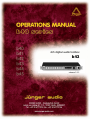
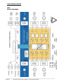
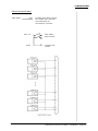
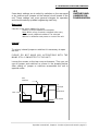
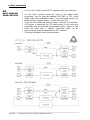
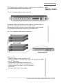
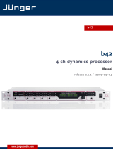
Junger Audio B43 is a 4-channel digital audio toolbox that provides a range of features for manipulating and processing audio signals in a professional studio environment.
With its 4x4 mix matrix, input and output gain control, automated fader function, audio delay, and level/overload display, the B43 allows for precise adjustment and manipulation of audio levels and signal routing. The unit also features a bit-transparent mode for input to output, ensuring that the original audio signal is maintained without any alterations.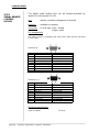


-
 1
1
-
 2
2
-
 3
3
-
 4
4
-
 5
5
-
 6
6
-
 7
7
-
 8
8
-
 9
9
-
 10
10
-
 11
11
-
 12
12
-
 13
13
-
 14
14
-
 15
15
-
 16
16
-
 17
17
-
 18
18
-
 19
19
-
 20
20
-
 21
21
-
 22
22
-
 23
23
-
 24
24
-
 25
25
-
 26
26
-
 27
27
-
 28
28
-
 29
29
-
 30
30
-
 31
31
-
 32
32
-
 33
33
-
 34
34
-
 35
35
-
 36
36
-
 37
37
-
 38
38
-
 39
39
-
 40
40


Junger Audio B43 is a 4-channel digital audio toolbox that provides a range of features for manipulating and processing audio signals in a professional studio environment.
With its 4x4 mix matrix, input and output gain control, automated fader function, audio delay, and level/overload display, the B43 allows for precise adjustment and manipulation of audio levels and signal routing. The unit also features a bit-transparent mode for input to output, ensuring that the original audio signal is maintained without any alterations.
Ask a question and I''ll find the answer in the document
Finding information in a document is now easier with AI
Related papers
-
 Junger Audio B40 User manual
-
 Junger Audio B42 User manual
-
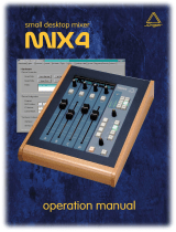 Junger Audio MIX4 User manual
-
 Junger Audio D*AP8 MAP User manual
-
 Junger Audio O_DAP_AMIC_a User manual
-
 Junger Audio T*AP User manual
-
 Junger Audio D*AP4 LM User manual
-
Junger Audio B44 User manual
-
 Junger Audio EASY LOUDNESS AoIP User manual
-
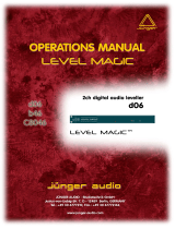 Junger Audio d06 User manual


Other documents
-
Crystal Vision ADCA402 User manual
-
AJA FS4 Installation and Operation Guide
-
-
-
TC Electronic DB6 User manual
-
-
TC Electronic LOUDNESS PILOT, AES3ID UNBAL Owner's manual
-
-
Harris CMN-41 Installation And Operation Handbook
-