Page is loading ...

D*AP4
Digital Audio Processor
D*AP4 FLX
D*AP4 LM Edition
Manual


DAP4-MEI_manual_EN_170315.doc
D*AP4
Hardware Features
•
1RU compact 19" processing device with front side info display
• Dual power supply second power supply for redundancy
• Front panel info display for signal activity, IP address, status alert
• Two hidden touch buttons to change the content of the info display
•
Remote Panel optional X*AP RM
1
panel
• Audio inputs balance/unbalanced AES – manual selection
•
Audio o
utputs
balance/unbalanced AES
• One interface slot I/O expansion slot for one option board at a time
• RJ45 network connector 100BaseT full duplex Ethernet interface
• USB B connector built in USB < > serial adapter to access the device service port
• 8 GPI/Os 8 balanced inputs, 8 relay closure combined on a 25pin D-Sub
•
Aux power supply isolated 5V supply for external wiring
•
External sync IN 75Ohm input (Word Clock, AES, Black Burst, Tri-Level)
•
Sync OUT 75Ohm Word Clock output
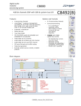
Software Features in general
The D*AP4 may be purchased as a Level Magic Edition and will appear as D*AP4 LM or based on the
software licenses of the FLX concept. In this case it appears as D*AP4 FLX.
Pls. contact your local dealer for details.
• LevelMagic loudness management according to ITU BS.1770-1/-2/-3
EBU R128, ATSC A/85, ARIB TR-B32, Free TV OP-59, Portaria 354
• Dynamic filter optional SPECTRAL SIGNATURE™ dynamic EQ
• EQ optional 5 band parametric
•
Dynamics optional compressor, expander / gate
• Fail over optional automatic switch over with signal loss detection
• Voice over optional stereo or mono voice over extra program input, pan
• FM Conditioner optional MPX limiter and Pre-Emphasis
• Loudness measurement in reference to the selected standard
•
SNMP agent SNMP v1, see D*AP4-MIB
• Remote control EmBER plus protocol or X*AP RM1 remote panel, mobile UI
and legacy GPI/Os
Operating Manual

D*AP4
1
Content
page
Introduction ………………………………………………………………………………………….. 3
D*AP4 front panel view ……………………………………………………………………………. 4
D*AP4 rear view ……………………………………………………………………………………. 4
Block Diagram ………………………………………………………………………………………. 5
Audio Processing Blocks …………………………………………………………………………. 6
Control, Operating & Event Concept …………………………………………………………….. 6
Getting Started – quick start guide ……………………………………………………………….. 7
Getting Started – IP setup in general ……………………………………………………………. 8
Getting Started – IP setup of the D*AP4 – via console interface ………………………….. 8
Getting Started – IP setup of the D*AP4 – via web browser ……………………………….. 9
Operating – menu structure of the X*AP RM1 remote panel ………………………………….. 10
Operating – menu structure of the X*AP RM1 remote panel – operating displays ………. . 10
Operating – menu structure of the X*AP RM1 remote panel – menu tree ………………….. 13
Setup GUI – connecting with the D*AP4 ………………………………………………………… 14
Setup GUI – SYSTEM – System Status ………………………………………………………… 15
Setup GUI – SYSTEM – Overview ………………………………………………………………. 16
Setup GUI – SYSTEM – Admin ………………………………………………………………….. 16
Setup GUI – SYSTEM – Setup …………………………………………………………………… 19
Setup GUI – SYSTEM – Remote Access – X*AP Remote ……………………………………. 20
Setup GUI – SYSTEM – Remote Access – Mobile UI …………………………………………. 21
Setup GUI – SYSTEM – the preset concept in detail ………………………………………… 22
Setup GUI – SYSTEM – Preset Cleanup ……………………………………………………….. 22
Setup GUI – SYSTEM – SNMP …………………………………………………………………… 23
Setup GUI – SYSTEM – Backup / Restore …………………………………………………….. 24
Setup GUI – SYSTEM – Firmware Update …………………………………………………….. 25
Setup GUI – SYSTEM – Reboot …………………………………………………………………. 25
Setup GUI – INTERFACES – AES I/O …………………………………………………………… 26
Setup GUI – INTERFACES – SDI I/O Interface – Overview ……………………………........ 28
Setup GUI – INTERFACES – SDI I/O Interface – Local Routing ………………………........ 29
Setup GUI – INTERFACES – SDI I/O Interface – Setup ………………................................. 30
Setup GUI – INTERFACES – SDI I/O Interface – De-Embedder …………………………..... 30
Setup GUI – INTERFACES – SDI I/O Interface – Embedder …………………………............ 31
Setup GUI – INTERFACES – MADI Interface – Status / Setup …………………………........ 32
Setup GUI – INTERFACES – MADI Interface – Local Routing …………………………........ 33
Setup GUI – INTERFACES – Dante I/O Interface – Status ………………………….............. 34
Setup GUI – INTERFACES – Dante I/O Interface – Inputs ………………………….............. 36
Setup GUI – INTERFACES – Dante I/O Interface – Ouputs …………………………............ 37
Setup GUI – INTERFACES – Dante I/O Interface – Network ………………………….......... 37
Setup GUI – INTERFACES – 4 Ch Analog I/O Interface …………………………................ 39
Setup GUI – INTERFACES – AES Interface – Status / Setup ……………………................ 40
Setup GUI – ROUTING ……………………………………………………………………………. 41
Setup GUI – AUDIO PROCESSOR – Overview ……………………………………………….. 42
Setup GUI – AUDIO PROCESSOR – Setup ……………………………………………………. 43
Setup GUI – AUDIO PROCESSOR – Input – Inputs …………………………….................... 44
Setup GUI – AUDIO PROCESSOR – Input – Phase Rotator ……………………………....... 44
Setup GUI – AUDIO PROCESSOR
– Fail Over .………………………………………………. 46
Setup GUI – AUDIO PROCESSOR
– De-Esser .………………………………………………. 46
Setup GUI – AUDIO PROCESSOR – Filter – Spectral Signature …………….................... 47
Setup GUI – AUDIO PROCESSOR – Filter – Equalizer ………………….............................. 50
Setup GUI – AUDIO PROCESSOR – Dynamics ………………………………………………. 52
Setup GUI – AUDIO PROCESSOR – Voice Over …………………………………………….. 54
Setup GUI – AUDIO PROCESSOR – Level Magic ………………………………………........ 55
Setup GUI – AUDIO PROCESSOR – FM Conditioner ……………………………................ 56
Setup GUI – AUDIO PROCESSOR – Output ………………………………………………….. 62
Setup GUI – AUDIO PROCESSOR – Delay …………………………………………………..... 63
Setup GUI – AUDIO PROCESSOR – Mobile UI ……………………………………………….. 63
Setup GUI – MESUREMENT – Setup ………………………….............................................. 65
Setup GUI – MESUREMENT – Loudness …………………………...................................... 66

D*AP4
2
Content
page
Setup GUI – EVENTS – Overview ………………………………………………………………. 67
Setup GUI – EVENTS – Triggers – Sources – Remote Hotkeys ……………………………. 68
Setup GUI – EVENTS – Triggers – Sources – Network ……………………………………… 69
Setup GUI – EVENTS – Triggers – Sources – Parameters ………………………………….. 69
Setup GUI – EVENTS – Triggers – Configuration – Trigger Equation ……………………… 70
Setup GUI – EVENTS – Events
– Preset Events ………………………………………..
71
Setup GUI – EVENTS – Events
– Parameter Events …………………………………..
72
Setup GUI – EVENTS – Events
–
Measurement Events …………………………………….. 73
Setup GUI – EVENTS – Events
–
I/O Events ………………………………………………….. 73
Setup GUI – EVENTS – Events
–
Bypass Events …………………………………………….. 74
Setup GUI – EVENTS – Actions
–
Event Actions …………………………………………….. 74
Setup GUI – EVENTS – Actions
–
Bypass Actions …………………………………………... 75
Technical Data – 4 Channel Audio Processor [D*AP4 LM EDITION, D*AP4 FLX] ………… 76
Technical Data – Option Board SDI I/O (3G/HD/SD) [O_DAP_SDI_a] ……………………… 77
Technical Data – Option Board Analog Out [O_DAP_8DA_a] ……………………………….. 78
Technical Data – Option Board Analog Out [O_DAP_ADDA_a] ……………………………... 79
Technical Data – Option Board AES/EBU I/O [O_DAP_AES_a] …………………………….. 80
Technical Data – Option Board MADI I/O, BNC [O_DAP_MB_a] ……………………………. 80
Technical Data – Option Board MADI I/O, Optical [O_DAP_MO_MM_a] …………………… 81
Technical Data – Option Board MADI I/O, Optical [O_DAP_MO_SM_a] …………………… 81
Technical Data – Option Board Audio-over-IP DANTE™ [O_DAP_DANTE_a] ……………. 82
Technical Data – Rear Connectors – pin assignment ………………………………………... 83
Technical Data – Optional Interface Modules – pin assignment ……………………………. 84
Technical Data – GPI wiring ……………………………………………………………………… 85
Safety Information …..…………………………………………………………………………… 86
Warranty …………………………………………………………………………………………….. 86

D*AP4
3
Introduction
The D*AP4 is a processing platform that may be bought in different versions as a 2 channel or 4 channel
processor. The D*AP4 LM is a fully featured loudness control device except EQs, Spectral Signature and FM
conditioner while the D*AP4 FLX will be tailor-made to your specification. Both devices may be upgraded
later on locally.
This manual refers to a fully featured D*AP4 LM.
The D*AP4 focuses on automatic and adaptive loudness management compliant with all current broadcast
audio loudness recommendations including ITU.1770 standards (revisions 1, 2 and 3) as well as
recommended practices ATSC A/85 (2011/2013), ARIB TR-B32, Free TV OP-59, Portaria 354 and EBU
R128. The D*AP4 features loudness normalization and dynamic range processing for up to two stereo
programs of audio. Sophisticated fail-over and voice-over round off the D*AP4 feature set. Dynamic range
control and Level Magic™ are based on a unique multi-loop control principle.
LEVEL MAGICII™
The algorithm offers adaptive wideband control with exceptionally high audio quality uncompromised
loudness management without any coloration, pumping, distortion or modulation effects by combining three
major gain changing elements:
· Transient Processor
· Adaptive AGC
· Distortion-free true peak limiter
Spectral Signature™
Jünger Audio’s Spectral Signature™ dynamic equalizer gives you a powerful creative tool to control the
spectral balance of your program. Spectral Signature™ analyzes incoming audio and compares its spectrum
with a predetermined reference curve. This allows dynamic EQ corrections to be applied, if necessary, to give
a consistent sound impression. Spectral Signature™ is an optional feature for the D*AP4.
FM Conditioner
A powerful option for FM broadcast and other FM applications like analog cable head ends to pre-control the
MPX power and peak deviation of a stereo FM signal, including true peak and pre-emphasis limiting.
System Integration
All system parameters are remotely accessible, allowing the unit to be integrated and remotely controlled by
broadcast control systems. This helps users to apply individual processing to their programs, which is a key
feature for well-managed loudness control.
Loudness measurement
To check compliance of programs with your local loudness regulations, the unit analyzes loudness and true
peak levels from input signals and transfers the measurement data via Ethernet to an optional measurement
and logging software anywhere in your network. These measurements can be triggered by automation
systems via GPIs, via network or even manually on the X*AP RM1 remote panel. The D*AP4 can also
generate SNMP or GPI/O alarms in case pre-determined limits are exceeded.
Web configuration
A web interface also allows easy and intuitive setup and configuration anywhere in your network.
Interfaces and system security
Audio I/Os range from onboard AES I/O to optional 3G/HD/SD-SDI I/O including video delay and analog I/O.
All combined I/O interfaces support power fail bypass relays as standard. With optional redundant PSU and
SNMP integration the unit ensures maximum operational safety.

D*AP4
4
D*AP4 front panel view
The front panel of the D*AP4 has a 3 line status display and two hidden touch buttons ~ 2.5cm left of the
display. Button 1 = Home will switch back to the power up display no matter which display level you are in.
Button 2 controls the multi level display:
Level 1 Power up display [Device type, firmware version]
Level 2 Status [OK / Error] / Device Name / IP address
Level 3 IN / OUT peak meter
Level 4 Program 1 Out - short term loudness
Level 5 Program 2 Out - short term loudness
Level 6 Program 1 Out - integrated loudness and integration time
Level 7 Program 2 Out - integrated loudness and integration time
The measures of the loudness displays depend on the setup of the respective loudness mode
(see AUDIO PROCESSOR > SETUP > Loudness Mode).
Display background Green = device status OK
color Red = device status ERROR
D*AP rear view
For fail safe operation, the D*AP4 provides two independent power supplies. These power supplies operate
in load balance. The status of both PSUs are combined with other status information and displayed as back
light color the front panel display.
STATUS shows the status of the device controller.
INIT / pressing the INIT button briefly will warm start the device controller.
RESET Holding down the button until the STATUS LED flashes 5 times will initialize the
D*AP4 to factory default
LAN RJ45 socket for Ethernet connection to a LAN
USB USB 2.0 type B socket to connect the built in USB >> serial converter with an
external PC
ISO-PWR lights up if the isolated 5V power supply for GPI /O application is turned on
Interface 1 slot to mount one of the optional interface boards (SDI, MADI, DANTE, AES,
analog)
GPI/O 25pin Sub-D female connector to interface with the 8 optical isolated general
purpose inputs and 8 solid state relay closure outputs
SYNC IN 75Ohm BNC connector to connect with external sync sources
WCLK-OUT 75Ohm BNC connector to synchronize external devices to the D*AP4 internal
word clock
AES 1/2 IN / OUT AES3 (XLR) and AES3id (BNC) input (selectable via GUI) / output (parallel)
AES 3/4 IN / OUT AES3 (XLR) and AES3id (BNC) input (selectable via GUI) / output (parallel)

D*AP4
5
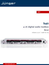
Block Diagram
The above schematic shows the principal blocks of the D*AP4.
The core of the unit is the audio processor with 4 inputs and 4 outputs.
An AES I/O on the motherboard is provided for digital line operation. The respective connectors have relay
bypass for power fail operation. The bypass ciruit may be disabled by an internal jumper. For the 2 channel
version only one AES I/O is fitted.
An interface slot is provided to carry optional 3G / HD / SD-SDI, AES I/O, MADI, DANTE or even analog
expansion modules. It allows for extremely flexible interfacing of the D*AP4 in TV or radio installations.
The sync. circuit can deal with all formats to integrate the D*AP4 into digital facilities with a sample rate from
44.1 or 48kHz. Other devices may be synchronized by the word clock output of the D*AP4.
The D*AP4 has 8 balanced GPIs and 8 relay closure GPO contacts. This enables the user to simply recall
presets or call events, change device configurations and report general status information.

D*AP4
6
Audio Processing Blocks
Above you see the various function blocks of the audio processor rendered by the DSP engine.
Each function block has its representation in the GUI by individual tab sheets. You may simply click on the
respective graphical area as an alternative way to navigate through the GUI.
It is important to understand that the physical input interfaces of the device (SDI DE-EMBEDDER, AES IN)
must be routed to the DSP inputs in order to process it. Similarly the DSP outputs must be routed to output
interfaces (SDI EMBEDDER, AES OUT). You will find those settings by clicking on the ROUTING tab.
Control Concept
The communication between external applications or the X*AP RM
1
remote panel, is based on
TCP/IP over Ethernet.
The setup GUI utilizes web technology. At the time of editing this manual the functionality of the web GUI is
optimized for Firefox 30.x and higher.
The setup GUI can be complemented by other application programs running on MS Windows® XP, W7, W8
like the Junger Application Manager J*AM. Operator access will also be available for mobile devices running
an appropriate browser on iOS or Android.
An SNMP agent may be activated to incorporate the device into a station monitoring system.
For 3
rd
party remote applications, Junger Audio highly recommends using the Ember+ protocol which is
widely distributed in the European broadcast industry. The user community is also increasing rapidly world
wide. By default, the X*AP RM
1
remote panel and the D*AP4 "talk" Ember natively.
Operating Concept
Further below you will see that the setup GUI for the device is grouped into several parameter areas.
One can reach the parameters via a 3 tier navigation by tabs which may have sub tabs, and the sub tabs may
have pages embedded or extra soft buttons for groups of parameters.
Each function block (parameter area) has dedicated presets. The presets can be recalled at any time during
operation, either by manual intervention via the embedded web server (browser based GUI), automatically
by the internal event manager or by external applications.
For all relevant settings an ON AIR and a PRESET part exists. I.e. you may either edit the parameters
ON AIR or offline for the respective part of the D*AP4.
The presets of the D*AP4 are persistent by nature. You are working directly on the preset memory.
I.e. you need not to worry about storing such presets, the D*AP4 does it for you.

D*AP4
7
Event Concept
The D*AP4 incorporates a sophisticated event management system.
Events may be combined to perform actions. The D*AP4 offers these event types:
* Preset Events for System set up, Interfaces, Routing, Audio Processing etc.
* I/O Events to control GPOs
* Bypass Events for pre-configured bypass scenarios
* Measurement Events to control loudness measurements per program
These events may be combined to form Actions which are fired by Triggers.
Triggers are defined by a logical combination (AND, OR, XOR) of two random trigger sources.
Trigger source may be GPIs, hotkeys of the X*AP RM
1
remote panel, network commands, parameters, other
active events, other active triggers (nested trigger), or device status information (e.g. sync lost).
Getting Started – quick start guide
Before the D*AP4 can be used, there are some basic configuration steps which must be followed in the order
set out below. This example assumes you will process one stereo program that is embedded into
SDI group1 Ch1/2.
* Connect the SDI signal (from a source like the station router or video server) to the SDI IN.
* Connect the SDI OUT connector to your destination device (station router or monitor box).
* Connect the BNC SYNC IN to the Black Burst reference of your TV station.
* Hook up the device to the station PC network
- Consult your IT administrator for assistance if you are not sure about this procedure
- Connect it to a switch or hub or directly to a PC / LapTop by an Ethernet cable
(some PCs need a cross over [1:1] cable when connected with the D*AP4 directly)
- Find an unused IP address - ask your administrator!
- Assign it that IP address and set the network mask accordingly, a gateway is optional
(see next page for details)
* Open a browser (FireFox recommended) and connect with the device
- Type in the IP address as an URL
* Set the sync source
- SYSTEM > Setup > Sync Source Priority > Choice 1=Sync-In BB
leave all other Choices x=OFF (for the beginning)
- SYSTEM > Setup > System Clock > Sample Rate=Follow Source
* Set the routing to the Audio Processor (DSP)
- ROUTING > SDI DE-EMBEDDER > DM1=DSP 1
- ROUTING > SDI DE-EMBEDDER > DM2=DSP 2
* Set the routing from the Audio Processor (DSP)
- ROUTING > DSP > DSP 1=SDI EMBEDDER > EMB 1
- ROUTING > DSP > DSP 2=SDI EMBEDDER > EMB 2
* Enable the SDI embdder
- INTERFACES > SDI I/O Interface > Embedder > SDI OUT Gr1=ON (check box)
- Check if the routing radio buttons will connect "From Routing EMB 1/2" to "SDI Out Gr1 1/2"
Now you should hear your source stereo program signal at the destination and you may start experimenting
with the various parameters of the audio processing blocks.

D*AP4
8
Getting Started – IP setup in general
The process of installing a D*AP4 into an IP network is as follows:
1. Ask the system administrator for a unique IP addresses of the network,
the netmask and gateway address
2. Assign the D*AP4 an IP address
You have 2 choices to assign the D*AP4 an IP address:
* From the serial console interface
* Via Web browser
Important Note! If you are not familiar with setting up devices for IP communication, we highly recommend
you consult your system service or IT department to assist you.
Getting Started – IP setup of the D*AP4
–
via console interface
The tool to change the IP configuration of the D*AP4 can be selected via the console interface. You must
connect it with the PC via an USB A to B cable. This will install the driver for the built-in USB to serial
converter. Now you can open a terminal program. Here you must select the virtual COM port assigned by
the OS. The communication parameters are:
115200kBaud, 8, N, 1 no hand shake. Pressing <ENTER> will open the console menu:
[2014-08-22 12:01] Your choice:
Select item "2": <ENTER>
Current network configuration
IP Address: 10.110.24.128
Netmask ...: 255.255.0.0
Gateway ...: 10.110.0.1
Enter new IP address, press ENTER to cancel:
You must enter the new IP address (e.g.): "192.168.178.78" <Enter>
Enter new netmask, press ENTER to cancel:
You must enter the new netmask (e.g.): "255.255.255.0" <Enter>
Enter new gateway address, press ENTER to configure without gateway:
You may press <Enter> to skip this point or
You may enter the new gateway address (e.g.): "192.168.178.1" <Enter>
Important Note! The gateway entry is optional but you must take care that the gateway address matches the
network mask related to the device IP address! If you are not sure simply enter 0.0.0.0.
or leave it without an entry.
Changing Network configuration
Network configuration has been changed. Please reboot the device
to activate the new settings.

D*AP4
9
Select item "8: Reboot" <ENTER>
Do you want to reboot the device ?
Press small "y" <ENTER>
Rebooting the device ……..
After reboot has finished, the new IP configuration is active and will be displayed at the top of the
configuration menu.
Getting Started – IP setup of the D*AP4
–
via web browser
* Read the default IP address printed on the label at the rear of the device.
* Set up network parameters of your PC to fit the default IP address of the D*AP4
(e.g. default IP +1 and net mask = 255.255.0.0).
* Connect the D*AP4 with the PC either by a Ethernet patch or a cross over cable
(if the PC does not support Auto MDI-X) or via a switch.
* Open a browser and type the default IP address of the D*AP4 into the URL field and press <ENTER>.
This will open the AUDIO PROCESSOR tab sheet of the GUI.
* Click on <SYSTEM> and afterwards the "Admin" tab:
Enter the desired network configuration and press <apply>
Afterwards you must reboot the D*AP4 in order to activate the new IP configuration.
Important Note! After reboot neither the web browser nor the X*AP RM
1
remote panel may be able to
communicate with the D*AP4. You must change back the IP configuration of the PC and fill in the new IP
address in the URL field. You must change the X*AP RM
1
remote panel settings as well to attach this device
again.

D*AP4
10
Operating - menu structure of the X*AP RM
1
remote panel
Power up display – may show up to four D*APx enabled for remote control for this X*AP RM
1
remote panel. The example below has just one D*AP4 unit [given name "TV3 HD"] attached for
remote control. The status is "connect" (i.e. you may connect with that device).
See X*AP RM1 manual for details.
Pressing that button will connect with that D*AP4.
Now the X*AP RM
1
remote panel will gather all necessary information from that D*AP4 unit
(this may take a few seconds). When finished the main operating display opens up:
From here you may fire pre-defined hotkeys and observe the loudness of the processed programs.
Because this is the main operating display, the <ESC> button lights red to indicate that the
power up display is below the main operating display.
Pressing <ESC> sends you back to the power up display (device selection).
Operating – menu structure of the X*AP RM
1
remote panel – operating displays
When you press the <MENU> button, the upper operating display opens up:
When pressing the <ESC> button you will return to the main operating display.
MENU
ESC
Remote Panel select device to control
TV3 HD
10.110.96.13
connect
MENU
ESC
R128 ITU1770 Loudn Lim D02 Limiter! Nicerizer [Panic 1 Panic 2]
Program 1 Program 2
-21.0
LUFS
-21.5
LUFS
EBU
S
out
MENU
ESC
Menu TV3 HD 10.110.96.15
Audio
Processor EBU R128
Meter

D*AP4
11
Operating display – EBU R128 Meter
The meter style (ITU BS.1770-x / ATSC / EBU etc.) is defined by the settings of:
AUDIO PROCESOR > Level Magic > Loudness Mode (example is for EBU R12().
The above menu serves as a display of measurement values and offers the metering control buttons
(reset & pause / continue).
<ESC> returns to the main operating display.
Operating display – Audio Processor
<ESC> returns to the operating display.
This menu gives access to tweak the various function blocks. The active <Shift> button indicates that
there is another page (2/2):
The example below explains how to set parameters via the X*AP. E.g. if you press <Input>
all parameters for the input function block will be accessible:
Here you are at the input section of the first program. The <Shift> button
again toggles between two pages and gains access to the remaining parameters:
MENU
ESC
Audio Processor TV3 HD 10.110.96.15 1/2
Phase
Rotator
Input Fail
Over
Spectral
Signature
Equalizer Dynamics Voice
Over
De-Esser
MENU
ESC
Audio Processor TV3 HD 10.110.96.15 2/2
FM
Conditioner
Level
Magic
Output
MENU
ESC
Input Link On Mute Gain[dB] Mono 1/2
V2 Linked On off 0.0 Stereo
L/R
Program 1
MENU
ESC
EBU R128 Int LRA Time
[LUFS] [LU] hh:mm:ss
Input -19.3 6.4
Output -23.2 5.8 00:12:15
Short-Term Max TPL Momentary
[dBTP] Max
-19.7 -6.6 -12.0
-21.3 -5.0 -16.0
reset max Program 1
pause
reset

D*AP4
12
Here is another example for page 2/2 after pressing the <Shift> button:
The D*AP4 knows two independent programs:
See SYSTEM > Setup > Program Configuration = 2 x 2. You can select between both here.
You are able to link / unlink the respective processing blocks (see AUDIO PROCESSOR > Input):
The above example shows both channels of "Program 1" (default name) in Linked mode.
When you press hotkey #2 you are able to unlink both channels. Now you must simply push the rotary
encoder (or turn it counter clockwise / clockwise) to toggle between Linked and Unlinked condition.
In case of Unlinked, the display shows two independent parameter sets.
By pressing hotkey # 1 you can toggle the between the channel that is under control:
The examples above demonstrates the general way how to setup parameters of the
AUDIO PROCESSOR of the D*AP4 VAP:
* Select a parameter
* Change it by using of the Rotary Encoder.
- Push it to toggle states
- Turn it to increment / decrement values.
Important Note! Not all processing blocks can be linked / unlinked. Carefully compare the settings via the
web GUI if you are not certain about individual settings. In general the X*AP RM
1
menus are a duplication of
the GUI settings. To access all parameters of a function block you must sometimes use the <Shift> button.
E.g. the equalizer has 5 pages for one program channel!
MENU
ESC
Input Delay Coarse [ms] Fine [samples] HPF [Hz] LPF [kHz] 2/2
1/2 0 0 OFF OFF
L/R
Program 1
MENU
ESC
Input Link On Mute Gain[dB] Mono 1/2
V2 Unlinked On off 0.0 Stereo
L/R Linked
Program 1
MENU
ESC
Input Link On Mute Gain[dB] Mono 1/2
L Unlinked On off 0.0 Stereo
V2 On off 0.0
R
Program 1

D*AP4
13
Operating – menu structure of the X*AP RM
1
remote panel – menu tree
Power Up Display – select a remote device
<MENU> opens X*AP RM
1
remote panel IP setup menu.
Hotkey #
1 <Address> setup
2 <Netmask> setup
3 <Gateway> setup
4 < empty >
5 Device 1 setup IP & ON / OFF
6 Device 2 setup IP & ON / OFF
7 Device 3 setup IP & ON / OFF
8 Device 4 setup IP & ON / OFF
<ESC> back to power up display
<connect> will connect with that particular D*AP4 and opens the main operating display:
Hotkey #
1 <R128>
2 <ITU1770>
3 <Loudn Lim>
4 <D02>
5 <Limiter!>
6 <Nicerizer>
7 <[Panic 1>
8 <Panic 2]>
<ESC> will jump back to power up display
<MENU> opens upper operating display:
Hotkey #
1 <empty>
2 <Audio Processor> opens up the function block selection
Hotkey # Hotkey # (after pressing <Shift>)
1 <Input> <Level Magic>
2 <Phase Rotator> <FM Conditioner>
3 <Spectral Signature> <empty>
4 <Fail Over> <empty>
5 <De-Esser> <empty>
6 <Dynamics> <empty>
7 <Level Magic> <empty>
8 <Voice Over> <Output>
<ESC> back to operating display
3 <empty>
4 <EBU R 128> opens the loudness meter display
Hotkey #
1 <Input>
2 <Fail Over>
3 <Spectral Signature>
4 <Equalizer>
5 <Dynamics>
6 <Voice Over>
7 <Level Magic>
8 <Output>
<ESC> returns to the upper operating display
5 <empty>
6 <empty>
7 <empty>
8 <empty>
<ESC> returns to the main operating display

D*AP4
14
Setup GUI – connecting with the D*AP4
You must open a browser and enter the IP address of the D*AP4
into the URL field and press <Enter>. The browser will retrieve the necessary information and open up the
entrance page:
The entrance page is the AUDIO PROCESSOR pane with its sub pane Overview. If you are returning from
other pages or if you reload your browser content (by pressing <F5>) it may show a different page due to
caching of the browser.
In the top section you see several bar graph displays for signal levels as well as for gain reduction display of
several function blocks.
On the following pages we will go through the various panes to perform the basic setup of the device.
You must set up the synchronization source. You may also give the device a name, tell it its location and
define an administrative contact which may be used by the monitoring system of your house (e.g. via SNMP).
You must set up the installed interface module and finally set the signal routing.
You will find those settings under the SYSTEM link.

D*AP4
15
Setup GUI – SYSTEM – System Status
The system status is a special link you can reach independently from where you are:
The System Status page provides a top level view of the various status information available for the device.
Device Status Provides the top level status of the D*AP4.
Power 1 Status of the first power supply (left hand side of rear).
Power 2 Status of second power supply (to the right of the first power supply)
Temperature Measured on the surface of the main PCB.
Sync Lock Turns red if the external sync source is lost or unstable.
NTP Server Status Is grey if the NTP server synchronization is turned off. It is green if the
clock is synchronized. Turns red if the clock can not be synchronized by
one of the NTP servers.
Processing Status
Bypass Turns red if Bypass is activated.
Interface Status
AES I/O Turns red if an AES input that is internally in use (i.e you have routed it to
an input of a function block) has detected an error.
System Messages [current / history]
Displays a list of messages produced by the system controller.
System Log The system controller activities will be logged. This log information may be
downloaded from the device and sent to Junger Audio. In case of a
problem you can press: <save diagnostics file> from here or from:
SYSTEM > Admin > Diagnostics.

D*AP4
16
Setup GUI – SYSTEM – Overview
The graphical overview shows the main building blocks of the device including the options installed,
in this example SDI interface placed into the interface 1 location (see rear view).
You may click on the boxes and the respective setup page will open. The navigation is based on URLs so
you may use the <Back> navigation button of the browser to return to this page.
Setup GUI – SYSTEM – Admin
/