Page is loading ...

TLED-NFS/NFM/NFL
INSTALLATION INSTRUCTIONS
800.533.3948 • www.barronltg.com
INSTALLATION INSTRUCTIONS
20070078 REV 1 06/14 1
SAVE THESE INSTRUCTIONS!
READ CAREFULLY AND FOLLOW ALL INSTRUCTIONS FOR YOUR OWN SAFETY
• DISCONNECT AC POWER SUPPLY BEFORE SERVICING.
• Installation and servicing of this equipment should be performed by qualified service personnel only.
• Ensure the electricity connections conform to the National Electrical Code and local regulations if applicable.
• Do not mount near gas or electrical heaters.
• Equipment should be mounted in locations and at heights where it will not readily be subjected to tampering by
unauthorized personnel.
• The use of accessory equipment not recommended by the manufacturer may cause an unsafe condition. Any
modification or use of non-original components will void the warranty and product liability.
• Do not use this equipment for other than intended use.
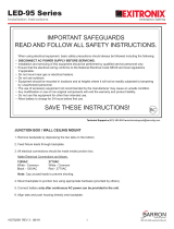
WALL MOUNT (Fig. 1)
TLED - NFS/NSM/NSL
1. Remove mounting plate by loosing (2) mounting screws.
2. Attach mounting plate to recessed junction box using hardware
provided with junction box ensuring plate is level.
3. Electrical connections should be made inside junction box. Cap
all unused leads to prevent shorting.
This fixture auto adjust for voltage between 120VAC – 277VAC.
a. Connect the line fixture lead to the black supply lead.
b. Connect the common fixture lead to the white supply lead.
c. Connect the ground lead from the service to the green
grounding screws.
4. Secure mounting plate to backplate by retightening (2)
screws.
SLIPFITTER MOUNT (Fig. 2)
TLED - NFM/NFL
1. Remove plugs and mounting plate by loosening (2) mounting
screws and discard.
2. Separate housing from backplate by loosening (4) screws
and set aside.
3. Attach slipfitter “Section A” to backplate using (2) screws,
lockwasher and washer. Ensure gasket is installed between
“Section A” and backplate.
4. Remove round cover plate.
5. Feed wires from Drivers through backplate and “Section A”.
6. Secure backplate to housing, retightening (4) screws.
Mounting
Plate
Backplate
Mounting Screws
Junction
Box
WALL MOUNT Fig. 1
Section A
Section B
Slipfitter
Mounting
Hardware
Round
Cover Plate
Locking
Bolt
Gasket
Backplate
SLIPFITTER MOUNT Fig. 2
Set
Screws
(4) Backplate
Screws
(5/16 - 18)
Plugs

7. Electrical connections should be made within slipfitter. Cap all unused leads to prevent shorting. This fixture auto
adjust for voltage between 120VAC - 277VAC.
a. Connect the line fixture lead to the black supply lead.
b. Connect the common fixture lead to the white supply lead.
c. Connect the ground lead from the service to the green grounding screws.
8. Loosen locking bolt inside round cover plate. Set desired angle and retighten.
9. Reinstall round cover plate.
10. Place slipfitter “Section B” over tennon and secure with (2) set screws on side.
ARM MOUNT (Fig. 3)
TLED-NFM/NFL
1. Remove plugs and mounting plate by loosening (2) mounting
screws and discard.
2. Separate housing from backplate by loosening (4) screws and
set side.
3. Attach arm to backplate, tightening anchor bolts with lock
washer and nut. Ensure gasket is installed between arm and
backplate.
4. Feed wires from driver through backplate and arm.
5. Secure blackplate to housing retightening (4) screws.
6. Electrical connections should be made inside junction box.
Cap all unused leads to prevent shorting.
This fixture auto adjust for voltage between 120VAC - 277VAC.
a. Connect the line fixture lead to the black supply lead.
b. Connect the common fixture lead to the white supply lead.
c. Connect the ground lead from the service to the green grounding screws.
KNUCKLE MOUNT (Fig. 4)
TLED – NFS
1. Remove plugs and mounting plate by loosening (2) mounting
screws and discard.
2. Attach “Section A” to backplate using (2) screws. Ensure
gasket is present between “Section A” and backplate.
3. Feed wires from driver through section A and B.
4. Electrical connections should be made inside junction box.
Cap all unused leads to prevent shorting.
This fixture auto adjust for voltage between 120VAC – 277VAC.
a. Connect the line fixture lead to the black supply lead.
b. Connect the common fixture lead to the white supply lead.
c. Connect the ground lead from the service to the green
grounding screws.
5. Loosen locking bolt and set desired angled and retighten.
6. Place “Section B” into weatherproof box cover / post top fitter, whichever applies.
INSTALLATION INSTRUCTIONS
800.533.3948 • www.barronltg.com
20070078 REV 1 06/14 2
Arm
Backplate Mounting
Hardware
Gaskets
Anchor
Bolts
Fig. 3ARM MOUNT
Plugs
Fig. 4KNUCKLE MOUNT
Section B
Section A
Backplate
Locking
Bolt
Knuckle
Screws
Plugs
TLED-NFS/NFM/NFL

INSTALLATION INSTRUCTIONS
800.533.3948 • www.barronltg.com
20070078 REV 1 06/14 3
NOTE: Fixture is suitable for uplight mounting.
IMPORTANT
To weather-proof your outdoor installation, be sure to seal all holes in fixture housing. (Mounting, conduit, plugs, and
photo controls, etc) with silicone sealant. Apply sealant across top edge of wall pack to prevent water from reaching
the back of the housing.
TROUBLE SHOOTING
If the unit does not turn “ON”
1. Check incoming voltage to LED driver. Must be at least a minimum of 120VAC and no greater than 277VAC.
2. Are all the LEDs on the light engine “OFF”? If so, LED driver may be defective. Using a voltmeter, check to see if
voltage is present at the output of power supply. If low or no voltage, then replace power supply.
3. If any individual LEDs are “OFF” the LED light engine is defective. Please have the serial number off the light
engine available when you contact technical support.
PHOTO CONTROL INSTALLATION INSTRUCTIONS
SAFETY PRECAUTIONS
1. Always turn off the power at the fuse or breaker box before installing a photo control.
2. Verify proper voltage. Make sure the supply line voltage matches the voltage in the photo control.
3. Directional Orientation. For best results be sure to position the photo control “eye” away from obstructions and
in the direction of the most natural light. Mounting under eaves or in front of trees will cause the photo control to
turn on earlier in the day. Make sure that your mounting is also directed away from any artificial light sources that
can interfere with normal operation at night (cycling on and off).
KNOCK OUT PROCEDURES
• Remove back plate.
• Remove knockout on outside of fixture and inner knockout where applicable.
• Remove any debris from knockouts.
• See Installation (Fig. 5) for TLED-NFM and TLED-NFL.
• See Installation (Fig. 6) for TLED-NFS.
4. Install photo control and secure with rubber gasket and plastic nut per details. (Caulking may be required to avoid
water entering into the unit).
5. Follow connections as shown in the wiring diagrams.
a. Connect Red wire (load) from photo control to LED driver(s).
b. Connect White wire (neutral) from photo control to light fixture (common).
c. Connect Black wire (line) from photo control to supply line voltage (hot).
TLED-NFS/NFM/NFL

INSTALLATION INSTRUCTIONS
800.533.3948 • www.barronltg.com
20070078 REV 1 06/14 4
6. TESTING: When the photo control is powered up the light will stay ON initially for approximately 60 seconds, once
the light turns OFF cover the eye of the photo control with a glove or other dark covering, after approximately 60–90
seconds the lights should turn back ON .
CAUTION: Incorrect wiring will cause faulty conditions or short through contact. Always verify the incoming Hot, Load,
and Neutral wires.
TLED-NFS/NFM/NFL
Load
Neutral
Line
Fig. 5
NFM/NFL
Fig. 6
NFS
Load
Neutral
Line
LED DRIVER
PHOTO
CONTROL
LINE
NEUTRAL
LOAD
HOT
BLACK
WHITE
COMMON
LED DRIVER
PHOTO
CONTROL
LED DRIVER
LINE
NEUTRAL
LOAD
HOT
COMMON
HOT
WHITE
BLACK
COMMON
Outside
Inner
WIRING DIAGRAM
NFL NFS/NFM
/