Page is loading ...

INTEGRATION GUIDE
CLIMATIX™
LON COMMUNICATION WITH
POL906.00

2
FläktGroup DC_8971GB 20180821_R0 Specifications are subject to alteration without notice
CONTENTS PAGE
ABOUT THIS DOCUMENT
REVISION HISTORY ........................................................................................................2
BEFORE YOU START ...................................................................................................... 2
REFERENCE DOCUMENTS ..........................................................................................2
DOCUMENT CONVENTIONS ........................................................................................ 3
IMPORTANT INFORMATION ON SAFETY ................................................................ 3
TRADEMARKS AND COPYRIGHTS ........................................................................... 4
QUALITY ASSURANCE .................................................................................................. 4
DOCUMENT USE/ REQUEST TO THE READER ...................................................4
LON NETWORKS
GENERAL DESIGN ..........................................................................................................4
INTERFACE AND TRANSMISSION ............................................................................5
TOPOLOGIES SPECIFICATIONS .................................................................................. 5
BUS TERMINATION .........................................................................................................5
COMMISSIONING INSTRUCTIONS
THE LON MODULE ..........................................................................................................6
CONNECT AND CONFIGURE LON MODULE ..........................................................6
INTEGRATION
GENERAL ............................................................................................................................ 8
UPDATE LON IMAGE/APPLICATION ........................................................................8
LON SNVTS ........................................................................................................................ 8
OTHER INFORMATION
TROUBLESHOOTING, TIPS ...........................................................................................9
UPGRADE APPLICATION OR BSP VIA SD CARD ...............................................9
OVERRIDE I/OS VIA COMMUNICATION ............................................................... 10
INDEX ..................................................................................................................................11
ABOUT THIS DOCUMENT
REVISION HISTORY
BEFORE YOU START
REFERENCE DOCUMENTS
FURTHER INFORMATION
The following documents contain additional information on the
products described in this manual:
VALIDITY
This document applies to the following products:
PRODUCT VERSIONS
Description and functional scope of the products are based on the
Climatix Valid Version Set 8.0 or higher and application based on
FläktGroup standard.
TARGET AUDIENCE
This document is intended for the following audience:
• LON system integrators
• Measuring and control engineering staff
• Sales and commissioning staff
PREREQUISITES
The above target audience:
• Has general professional knowledge on planning and commissioning
HVAC technology measuring and control solutions.
• Has basic knowledge of LON.
• Has the additional SNVTs documentation for the specific product.
Version Date Changes Section Pages
26.01.2011 First edition
Name Type (ASN) Version
LON communication module POL906.00/STD LON module
Document Order No.
Data sheet ”Communication module LON” CB1Q3931en
SNVTs ”LON communication with POL906.00”
Note!
Unique documentation for each application:
eQ AHU (eQ fläkt)
eQ zone
Twin Wheel
8972
8973
8974

3
FläktGroup DC_8971GB 20180821_R0 Specifications are subject to alteration without notice
DOCUMENT CONVENTIONS
SYMBOLS USED
Below is an overview of all symbols used in this document denoting
risks or important information:
This symbol draws your attention to special safety notes and
warnings. Failing to observe these notes may result in injury
and/or serious damages.
This symbol denotes special information that, when failed to
observe, may result in faulty functionality or loss of data.
Notes with this symbol provide important information that
requires appropriate attention.
This symbol marks passages containing tips and tricks.
ABBREVIATIONS
The following abbreviations are used in text and illustrations:
Abbreviation Meaning
BACS Building Automation and Control System
BSP Board Support Package (operating system)
Climatix Controller family with common tools
CPT Configuration Property Type (LON)
FTT-10A Free Topology Transceiver for channel type TP/FT-10
(LON)
HMI Human Machine Interface, e.g Operator unit
HMI-DM Climatix Dot Matrix HMI, POL895.51
HVAC Heating, Ventilating, Air Conditioning
LON Local Operating Network
LNS LonWorks Network Service (LON interface)
MS Management Station
NV Network Variable (LON)
SELV Safety Extra-Low Voltage
SNVT Standard Network Variable Type (LON)
TP/FT-10 Physical channel to transmit data over Twisted Pair to
Free Topology networks.
STOP
STOP
STOP
STOP
IMPORTANT INFORMATION ON SAFETY
FIELD OF APPLICATION
Use LON communication only for control and monitoring.
INTENDED USE
Trouble-free and safe product operation of the above products
presupposes transport, storage, mounting, installation, and
commissioning as intended as well as careful operation.
ELECTRICAL INSTALLATION
Fuses, switches, wiring and grounding must comply with local
safety regulations for electrical installations.
WIRING
When wiring, strictly separate AC 230 V mains voltage from
AC 24 V safety extralow voltage (SELV) to protect against
electrical shock!
COMMISSIONING AND MAINTENANCE
Only qualified staff trained accordingly may prepare for use,
commission, and maintain LON communication modules.
MAINTENANCE
Maintenance of Climatix controller and LON communication modules
generally only means regular cleaning. We recommend removing dust
and dirt from system components installed in the control panels during
standard service.
FAU LTS
Only authorized staff may diagnose and correct faults and
recommission the plant. This applies to working within the
panel as well (e.g. testing or changing fuses).
STORAGE AND TRANSPORT
Refer to the environmental conditions specified in the respective data
sheets for storage and transport.
If in doubt, contact your supplier.
DISPOSAL
Devices contain electrical and electronic components; do not dispose
of them in household garbage.
Observe all local and applicable laws.
STOP
STOP
STOP

4
FläktGroup DC_8971GB 20180821_R0 Specifications are subject to alteration without notice
TRADEMARKS AND COPYRIGHTS
QUALITY ASSURANCE
DOCUMENT USE/ REQUEST TO THE READER
TRADEMARKS, LEGAL OWNERS
The table below lists the third-party trademarks used in this
document and their legal owners. The use of trademarks is subject to
international and domestic provisions of the law.
COPYRIGHT
The table below lists the third-party trademarks used in this
document and their legal owners. The use of trademarks is subject to
international and domestic provisions of the law.
DOCUMENT CONTENTS
These documents were prepared with great care.
• The contents of all documents are checked at regular intervals.
• All necessary corrections are included in subsequent versions.
• Documents are automatically amended as a consequence of
modifications and corrections to the products described.
Please make sure that you are aware of the latest document revision
date.
REQUEST TO THE READER
Before using our products, it is important that you read the documents
supplied with or ordered at the same time as the products (equipment,
applications, tools etc.) carefully and in full.
We assume that persons using our products and documents are
authorized and trained appropriately and have the technical knowledge
required to use our products as intended.
EXEMPTION FROM LIABILITY
FläktGroup assumes no liability to the extent allowed under the law for
any losses resulting from a failure to comply with the aforementioned
points or for the improper compliance of the same.
All product names listed in the table are registered (
®
) or not registered
(™) trademarks of the owner listed in the table. We forgo the labeling
(e.g. using the symbols
®
and ™) of trademarks for the purposes of
legibility based on the reference in this section.
Trademarks Legal owner
LonLink™
LON® / LonManager®
LonMark®
LonTalk®
LonWorks®
Echelon Corporation
Microsoft
Microsoft Corporation see
https://www.microsoft.com/en-us/legal/
intellectualproperty/trademarks/usage/
general.aspx
Neuron®Echelon Corporation
Element Explanation
MS
Management station, PC with:
VNI (Virtual Network Interface)
LNS (LonWorks Network Services)
Tools: BAC software, engineering tool (e.g. LonMaker
and possibly SCOPE).
Backbone E.g. Ethernet TCP/IP, interconnects building networks.
Channel Physical LON transmission channel, e.g. TP/FT-10.
Router (Rt) Interconnect subnets.
Segment Physical segment of a channel.
Repeater (Rp) Interconnect segments. No processing function.
Nodes (N) LON node: Device with Neuron Chip
(controller, interface etc.).
Tool
PC with LON tool (NL220, LonMaker):
– Load LON application.
– Create bindings.
Term Explanation ID
Domain Comprises max. 255 subnets. 1 … 248
Subnet Comprises max. 127 nodes. 1 … 255
Node Smallest, addressable unit. 1 … 127
LON NETWORKS
GENERAL DESIGN
PHYSICAL DESIGN
The figure shows the physical design for a general LON network:
ELEMENTS
Displayed elements:
LOGICAL ORGANIZATION
A LON network is divided into domain, subnet, and node. A logical,
unique address (ID) is assigned to each LON node accordingly:
MORE INFORMATION ON LON
See www.echelon.com and www.lonmark.org
P3931Z09
N
Rt Rp
Rt
N N N N
Segment
Channel
Segment
VNI
N N N N N N N N
LNS Tools PC MS
Channel / Segment
BackboneTool
LON
LON

5
FläktGroup DC_8971GB 20180821_R0 Specifications are subject to alteration without notice
INTERFACE AND TRANSMISSION TOPOLOGIES SPECIFICATIONS
BUS TERMINATION
FTT-10A TRANSCEIVER
The LON communication module comes with a FTT-10A bus coupling unit.
This “Free Topology Transceiver” for Neuron Chip-based devices was
developed by Echelon as a successor to the FTT-10 for simple creation
and extension of LonWorks networks with channel type TP/FT-10.
ALLOWED TOPOLOGIES
The following topologies are possible for devices with FTT-10A transceiver:
• Free topology (including star and ring topologies).
• Line topology (bus topology).
TP/FT-10 CHANNEL TYPE
TP/FT-10 stands for “Twisted Pair / Free Topology”.
It specifies a physical channel for data transmission to free topology
networks using twisted pair at a transfer rate of 78 kbps.
Channel type TP/FT-10 is LonMark®-certified.
CABLE TYPES
Echelon allows three cable types for channel type TP/FT-10, including
the Category 5 network cable used commonly in building automation
and control (TIA 568A Cat-5).
CAT-5 SPECIFICATIONS
Unshielded cable, twisted pair with at least 18 beats per meter:
PRIMARY DATA
Below are the lists of all primary data for individual elements regarding:
• Free topology
• Line topology
The max. distance and length apply to network cables Category 5 (TIA
Cat-5) as per section 2.2 “Interface and transmission”:
FREE TOPOLOGY
LINE TOPOLOGY
REPEATER AND ROUTER
Repeaters and router are used in the following cases:
Repeater and router
• The entire cable length in a physical segment exceeds 450 m (in a
free topology) or 900 m (in a line topology).
• The max. possible number of nodes per physical segment is
exceeded: 64 nodes with FTT-10A transceivers.
Each trunk can have max. one physical repeater.
Repeaters or routers may not be used in a ring topology. They
must be placed before the network's ring port.
*) LPT-10: "Link Power Transceiver" by Echelon. Compatible to FTT-10A. Offers
the advantage that voltage supply for nodes can also be run via the bus line.
Requires special link-power power supplies.
BUS TERMINATION
Bus terminators are used for properly terminating a network based on
twisted pair-technology with regard to impedance. Use the following
terminators in dependence of the topology:
• Free topology: 1 bus terminator 52.3 Ω at busiest point of network.
• Line topology: 2 bus terminators 105 Ω at both network ends.
Terminators often are integrated in system devices and can be
activated via switches or jumpers.
Element Value
Max. distance between the two nodes farthest
apart in a given physical segment. 250 m
Max. cable length in a segment.
(Total of all lines including lines to room units). 450 m
Max. number of nodes per physical segment.
The following formula applies to mixed
configurations of FTT-10A and LPT-10 transceivers:
(1 x number of LPT-10) + (2 x number of FTT-10A) ≤ 128
64 FTT-10A
128 LPT-10 *)
Bus terminator at the busiest point of the physical
segment, i.e. the area with the highest network data
traffic (e.g. at master).
52.3 Ω
Element Value
Max. cable length per physical segment. 900 m
Maximum stub line length.
The same also applies to connections to room units.
3 m
Max. number of nodes per physical segment.
The following formula applies to mixed
configurations of devices with FTT-10A and LPT-10
transceivers:
(1 x number of LPT-10) + (2 x number of FTT-10A) ≤ 128
64 FTT-10A
128 LPT-10 *)
Bus terminators at each end of the physical
segment. 105 Ω both ends
Cross-sectional area Min. ∅ 0.5mm, AWG24, 0.22mm²
Impedance 100 Ω +/- 15 % @ f > 1 MHz
Operating capacity between two
wires of a pair.
< 46 nF/km
Capacity pair to ground,
asymmetric.
< 3.3 nF/km
DC loop resistance < 168 Ω
Cable length See section 2.3 ”Topologies
specifications”
STOP
STOP

6
FläktGroup DC_8971GB 20180821_R0 Specifications are subject to alteration without notice
THE LON MODULE
COMMISSIONING INSTRUCTIONS
DESIGN
The figure shows the LON module. It is connected to the Climatix
controller via the internal communication extension bus. This is done
via plug connection on the left side of the controller.
ELEMENTS AND CONNECTIONS
The elements and connections in the figure are:
STATUS DISPLAYS
The status LEDs "BSP" and "BUS" can light red, green and yellow in
operation.
Pos. Element / Connection
1
LON interface. Plug connection: Screw/terminal connection.
2“Service” pin; see section 3.2
“Connect and configure LON module”.
3Status display “BSP” (Board Support Package).
4Status display “BUS” (bus connections o.k. / bus traffic).
5Plug connection “Communication extension bus”.
6Climatix controller POL6XX.
STOP
STOP
Power supply is outside the allowed range if both LEDs are
dark.
"BSP" LED
This LED informs on the status of the "Board Support Package" (BSP).
Color and flashing frequency of the LED:
"BUS" LED
This LED shows the status of external communication with the bus, not
to the controller. Color and flashing frequency of the LED:
Color Flashing frequency Meaning / Mode
Red / yellow 1 s “on” / 1 s “off” Upgrade mode.
Green Steady “on”
BSP operating and
communication with
controller working.
Yellow Steady “on”
BSP operating, but no
communication with
controller.
Red Flashing at 2Hz BSP error (software error).
Red Steady “on” Hardware fault.
Color Flashing frequency Meaning / Mode
Green Steady “on”
Ready for communication
(all parameters loaded,
Neuron configured). Does not
indicate communication with
other devices.
Red Steady “on”
No communication to Neuron
(internal error, could be
solved by downloading a
new LON application).
Yellow Steady “on” Startup
Yellow Flashing
Communication not possible
to the Neuron. The Neuron
must be configured and set
online over the LON Tool.
CONNECT AND CONFIGURE LON MODULE
Prerequisites for connecting and configuring:
Working application loaded and started in the Climatix
controller.
DEVICES INVOLVED
The Climatix POL6XX controller and the LON module POL906 are
involved in this action:
TOOLS
Tools used:
– Operator unit (HMI)
– PC with LON tool (NL220, LonMaker).
SIEMENS
6
5
SIEMENS
LON
Service
CLA
CLB
P3931Z05
1
2
3
4
BSP BUS
P3931Z14
LON bus
POL906 / POL6XX
HMI
PC
LON tool Service
BSP BUS

7
FläktGroup DC_8971GB 20180821_R0 Specifications are subject to alteration without notice
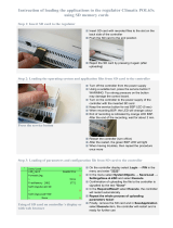
Step Action Type
1
Controller
OFF
2Connect LON module to controller using plug connection.
3Connect LON bus cable to the module.
4
Controller ON:
→ The module starts / initialization begins.
→ As soon as the two LEDs "BSP" and "BUS" are steady
green, communication with the controller and bus (LON)
is active.
5
Carry out a further restart: Switch the power supply
OFF / ON.
Caution!
The controller must be reset a second time to update HMI;
prior to parameterization.
Step Action Type
1Log in to HMI-DM using the password for level 4 (Service),
default 2000.
2
Go to:
MAIN INDEX Ú SYSTEM OVERVIEW Ú COMMUNICATION Ú
COMM MODULE OVERVIEW Ú MODULE[X] LON Ú
Note!
[x] is the position of the connected communication module.
This is only information used when more than one module
is connected.
3
Go to SETTINGS Ú
Set up Heart beat and Min send interval if needed. See
parameter list on next page.
4
Select RESET REQUIRED !!:
When done, restart controller using this command by
first going back two pages, with ESC, to COMM MODULE
OVERVIEW.
Parameter Function
Service pin* Executes a software trig for the service pin
State Current status of the communication module
Comm
failure
Communications error between module and processor
(e.g. no LON application loaded on the Neuron chip).
Location Displays an information, which may be set at commis-
sioning the bus via LON Chip.
Application Name of loaded LON image/application (list of LON
variable) on the Neuron chip.
Neuron-ID Displays ID number for the Neuron chips.
Send heart
beat Displays current interval for sending values.
Receive
heart beat Displays current interval for receiving values.
Min send
interval
Displays current minimum interval for sending values.
A value may only be sent a maximum of one time
during this interval.
Settings Go to settings page to parameterize LON module.
Software
version Module BSP version.
Device ID Module hardware ID.
Module Displays module type (e.g. POL906LON).
Parameter Range Function
Send heart
beat 0…65535 [s] Set interval for sending values.
Receive
heart beat 0…65535 [s] Set interval for receiving values.
Min send
interval 0…65535 [s] Set minimum interval for sending
values.
Use default – Passive
– Active
Reset communication module
parameterization to default setting.
CONNECT LON MODULE
Proceed as follows to connect the LON module to the bus:
(see also description and picture in the previous section)
CONFIGURATION VIA OPERATOR UNIT
Proceed as follows to configure the LON module:
PARAMETER LIST
The following table lists all LON module parameters which are
displayed by the HMI. Menu item:
LON MODULE PARAMETERIZATION
The following parameters can be set via the HMI. Menu item:
After restart, the LON module is configured and ready to use.
As a matter of principle, the controller must be restarted with
“Reset required !!” or power off/on the controller after changing
any settings to assume the data.
MAIN INDEX
Ú
SYSTEM OVERVIEW
Ú
COMMUNICATION
Ú COMM MODULE OVERVIEW Ú
MODULE[X] LON
MAIN INDEX
Ú
SYSTEM OVERVIEW
Ú
COMMUNICATION
Ú COMM MODULE OVERVIEW Ú
MODULE[X] LON Ú SETTINGS
STOP

8
FläktGroup DC_8971GB 20180821_R0 Specifications are subject to alteration without notice
CONNECT TO THE LON BUS
Proceed as follows to connect the LON module to the LON bus:
LON IMAGE/APPLICATION XIF FILE
The LON module's Neuron application supports 62 network variables
to integrate controllers in a management station, and allow controllers
to exchange data over LON. The LON module is per default loaded with
LON image/application set (XIF file) ClimatixAHU V1.x.
SOFTWARE
A special LON tool (for ex. LN220, LON Maker) must be used to
configure the network, bind the variables and to observe the SNVTs.
The tool can also be used to download new updated LON images (XIF
files) if necessary. To communicate with the LON device the PC must
have an LON interface (card) installed as well.
INTEGRATION TYPES
The integration can me made using either pooling or binding. A
bound system is COV based and the communication is only active at
changes.
UPDATE LON IMAGE/APPLICATION
UPDATE VERSION OR SNVT SET
The LON image/application can be updated to another version or
another SNVT set via the LON tool connected to the LON network.
Normally only the XIF file is selected but the whole image/application
contains more needed files.
The procedure can be different depending on LON tool so this can not
be fully described here.
USE THE RIGHT DOCUMENT FOR ACTUAL APPLICATION
All available SNVT’s are found in a separate document and are specific
for the actual application. All different applications, and in some cases
also application versions, have different SNVT’s mapping. The specific
document for the actual application must be used to see what SNVT’s
that are used.
The actual application name and version can be found using
the HMI-DM. In some cases it is also good to check the
controller BSP version.
Check actual application
Proceed as follows to see the actual application name and version:
1. Log in to HMI-DM using the password for level 4 (Service),
default 2000.
2. Select MAIN INDEX Ú SYSTEM OVERVIEW Ú APPLICATION INFO Ú
UPDATE THE LON IMAGE
Proceed as follows to load the LON module with the needed LON
image/application:
See further instructions how to update the LON module if the
application needs another LON application/image than the
default ClimatixAHU v1.x.
You can find current general descriptions of SNVTs (Standard
Network Variable Types) used in LON image on the homepage
of "LonMark International" at:
http://types.lonmark.org/index.html
"LONMARK Resource Files, version XX.XX"
Step Action Type
1
Generate a new node in the LON tool (preparation).
2
Press the "Service" pin on the LON module or execute the
software service pin from the HMI:
→ The module is recognized and displayed in the LON tool.
→ All network variables are available.
3Assign the logical address.
Step Action Type
1
Generate a new node in the LON tool (preparation).
2
Press the "Service" pin on the LON module or execute the
software service pin from the HMI:
→ The module is recognized and displayed in the LON tool.
→ All network variables are available.
3Load the individual LON application (file “XY.XIF”).
Standard application ClimatixAHU V1.x is loaded by default.
4
Restart the controller with “Reset required !!” or power off/on.
STOP
STOP
STOP
GENERAL
LON SNVTS
INTEGRATION
Parameter Explanation / Example
Application manufacturer e.g. FläktGroup
Application name and version e.g. eQ fläkt v1.30.10
Date Application creation date
Name e.g. plant name.
Street e.g. plant address.
City e.g. plant address.

9
FläktGroup DC_8971GB 20180821_R0 Specifications are subject to alteration without notice
GENERAL
General things to check:
• Check the actual application version, controller BSP and
communication module BSP version before call any support.
• As a matter of principle, the controller must be restarted with “Reset
required !!” or power off/on after changing any settings to assume
the data.
• Use the "Use default" parameter to go back to default setting
of the communication module, reset the controller, and do the
parameterization again.
BUS TERMINATION ERROR STATES
Errors from bus termination may result in the following states:
• Signal level too low.
• Signal level (too) high.
SIGNAL LEVEL TOO LOW
Possible causes:
• Wrong bus terminator.
• Too many bus terminators (e.g. integrated bus terminator in repeater
or bus supply not considered).
SIGNAL LEVEL (TOO) HIGH
Possible causes:
• A high-level signal or signal reflections point to a missing or wrong
bus terminator.
• Bus terminator placed incorrectly: → Find the busiest point in the
network through trial and error.
MIN SEND TIME
Some output (nvo) SNVTs use the “Min send time”. Means that this
SNVTs have fastest send interval of x seconds.
SNVT_STATE
Climatix are using SNVT_state binary counted from left to right and due
to that some LON devices counts from right. In this case it is neces-
sary to invert the bits, Bit0=Bit15, Bit1=Bit14....
SNVT_SWITCH
The state part for SNVT_switch must be set to 1 (Active) to use the
value part.
XIF FILE
The XIF file can be opened and read with a text editor like Notepad.
SITUATION
The Climatix POL6XX controller and/or the LON module POL906 can in
special cases be updated with new software.
PREREQUISITE
To upgrade the following items are needed:
• SD card
• Application- and/or BSP files from the actual manufacturer:
UPGRADE PROCEDURE
The upgrade procedure and how to save/load all settings are not
described in this manual. See basic documentation for the specific
product depending of what upgrade is needed.
CHECK ACTUAL CONTROLLER BSP VERSION
Proceed as follows to see the actual controller BSP version:
1. Log in to HMI-DM using the password for level 4 (Service),
default 2000.
2. Select MAIN INDEX Ú SYSTEM OVERVIEW Ú TARGET Ú
* These files may set all settings in the controller to default!
All settings can be saved to the SD card before the upgrade
and then loaded again after the upgrade.
STOP
TROUBLESHOOTING, TIPS
UPGRADE APPLICATION OR BSP VIA SD CARD
OTHER INFORMATION
Parameter Explanation / Example
BSP version Controller operating system.
File Used for…
POL8193.hex LON Communication module, POL906, BSP
POL63x.hex Controller, POL63x, BSP*
MBRTCode.bin Controller, POL63x, Application*
OBH.bin Controller, POL63x, Communication mappings
HMI/HMI4Web.bin Controller, HMI structure
STOP
POL906 / POL6XX BSPBUS
SD
LON bus
P3931Z13en

10
FläktGroup DC_8971GB 20180821_R0 Specifications are subject to alteration without notice
PREAMBLE
Some inputs can be overridden via LON, see SNVTs list. However these
inputs must first be setup for this before it works. Inputs can work only
via hardware, only via communication or as a combination.
PREREQUISITE
Input must first be enabled and hardware place selected in configuration.
CONFIGURATION VIA OPERATOR UNIT
Proceed as follows to select input handling:
OVERRIDE I/OS VIA COMMUNICATION
Step Action Type
1
Log in to HMI using the password for level 4 (Service),
default 2000.
2
Select MAIN INDEX Ú UNIT Ú INPUTS Ú
ELEMENT GROUP Ú ELEMENT Ú
Example:
MAIN INDEX Ú UNIT Ú INPUTS Ú TEMPERATURES Ú
OUTSIDE TEMP Ú
3Select SPECIAL SETTINGS Ú VALUE SELECTOR,
see selections below
Parameter Range Function
Value
selector
(Digital
inputs)
– Hardware
– Comm
– And
– Or
– PreferedHW
– PrefComm
Select valid input value for the
application:
– Value on hardware input.
– Value from communications.
– The input is 1, if the value on the
hardware input and the value from
communications = 1. Alarm triggers, if
one of the two values is invalid.
– The input is 1, if the value on the
hardware input or the value from
communications = 1. Alarm triggers, if
one of the two values is invalid.
– Value on hardware input has priority.
The value from communications
assumed if invalid. Alarm triggers, if
both values are invalid.
– Value from communications has
priority. The value from hardware input
assumed if invalid. Alarm triggers, if
both values are invalid.
Value
selector
(Analog
inputs)
– Hardware
– Comm
– Average
– Minimum
– Maximum
– PreferedHW
– PrefComm
Select valid input value for the
application:
–
Value on hardware input.
–
Value from communications.
–
Average from the values on
hardware input and from
communications. Alarm triggers, if
one of the two values is invalid.
–
Lowest value from the values
on hardware input and from
communications. Alarm triggers, if
one of the two values is invalid.
–
Highest value from the values
on hardware input and from
communications. Alarm triggers, if
one of the two values is invalid.
–
Value on hardware input has priority.
The value from communications
assumed if invalid. Alarm triggers, if
both values are invalid.
–
Value from communications has
priority. The value from hardware
input assumed if invalid. Alarm
triggers, if both values are invalid.

11
FläktGroup DC_8971GB 20180821_R0 Specifications are subject to alteration without notice
INDEX
A
Abbreviations in document.........................................................................................3
Application information ................................................................................................8
B
Before you start ............................................................................................................... 2
Bus termination ...............................................................................................................5
C
Connect and configure LON module .......................................................................6
D
Document use, request to the reader....................................................................4
Documents, other ...........................................................................................................2
I
I/Os via communication ............................................................................................10
Integration
General ..........................................................................................................................8
Update LON image/application ........................................................................... 8
L
LON image/application ................................................................................................8
LON interface and transmission ............................................................................... 5
LON networks
General design ...........................................................................................................4
LON SNVTs .........................................................................................................................8
Q
Quality assurance ...........................................................................................................4
S
Safety notes ......................................................................................................................3
Symbols in document ................................................................................................... 3
T
The LON module .............................................................................................................. 6
Topologies specifications ............................................................................................ 5
Trademarks and copyrights .......................................................................................4
Troubleshooting, tips .....................................................................................................9
U
Upgrade via SD card .....................................................................................................9
X
XIF file..................................................................................................................................9

WWW.FLAKTGROUP.COM CLIMATIX™
» Learn more on www.flaktgroup.com
or contact one of our offices
FG_DC_8971GB_Climatix LON integration_CO_20180821_R0 © Copyright 2018 FläktGroup
FläktGroup is the European market leader for smart and energy efficient Indoor Air
and Critical Air solutions to support every application area. We offer our customers
innovative technologies, high quality and outstanding performance supported by more
than a century of accumulated industry experience. The widest product range in
the market, and strong market presence in 65 countries worldwide, guarantee
that we are always by your side, ready to deliver Excellence in Solutions.
PRODUCT FUNCTIONS BY FLÄKTGROUP
Air Treatment | Air Movement | Air Diffusion | Air Distribution | Air Filtration
Air Management & ATD’s | Air Conditioning & Heating | Controls | Service
/