4
2 .When PV, Grid is available(without battery):
A. Solar energy provides power to the loads as first priority ,if solar energy is
sufficient, the excess power will feed to grid.
Inverter
PV Grid
EPS
Inverter
PV Grid
EPS
Inverter
PV
BAT EPS
Inverter
PV
BAT EPS
A. On charge time, grid will charge battery and supply power to the connected
loads at the same time.
2. When Grid, Battery is available(PV is disconnected):
B. On discharge time, if load power is less than battery power, battery will
supply power to loads as first priority, the excess power will be feed to grid.
D. In the period of no charge or discharge, the solar power supply loads at first
priority , excess energy to the grid.
C. On discharge time, if load power is more than battery power, battery and grid
will supply power to the loads at the same time.
Inverter
PV
BAT EPS
Grid
Inverter
PV
BAT EPS
Inverter
PV
BAT EPS
Grid
Grid
Inverter
PV
BAT EPS
Grid
Inverter
BAT EPS
Grid
Inverter
BAT EPS
Grid
Inverter
BAT EPS
Grid
Inverter
PV
BAT
Grid
EPS
Inverter
PV
BAT
Grid
EPS
Inverter
PV
BAT
Grid
EPS
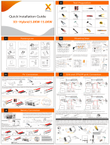
1.4 Work Modes
Hybrid Inverter provides multiple work modes based on different requirements.
Work modes: Self-use
1.When PV, Grid, Battery is available:
A. Solar energy provides power to the loads as first priority, if solar energy is
sufficient to power all connected loads, solar energy excess power will
provides to charge battery, and then reduntant power will feed to grid.
C. Solar energy provides power to the loads as first priority ,if solar energy and
battery are not sufficient to power all connected loads, utility energy (Main
Grid) will supply power to the loads with solar energy at the same time.
B. Solar energy provides power to the loads as first priority, if solar energy is
not sufficient to power all connected loads, Grid energy will supply power to
the loads at the same time.
B. Solar energy provides power to the loads as first priority ,if solar energy is
not sufficient to power all connected loads, battery energy and solar energy
will supply power to the loads at the same time.
3 .When PV, Battery is available(Grid is disconnected):
A. Solar energy provides power to the loads as first priority ,if solar energy is
sufficient to power all connected loads, solar energy will provides to charge
battery.
B. Solar energy provides power to the loads as first priority ,if solar energy is
not sufficient to power all connected loads, battery energy will supply power to
the loads at the same time.
Work modes: Peak shift
1.When PV, Grid, Battery is available:
A. On charge time, solar energy will charge battery as first priority. The excess
energy will supply power to the loads.If solar energy is sufficient to supply loads
and charge battery,and If there's still some extra energy, then the excess
power will feed the power to grid
B. On charge time, solar energy will charge battery as first priority.then the
excess solar energy will supply power to loads.If solar energy is not sufficient to
charge battery and supply loads, grid will supply all the connected loads with
solar energy together.
C. On discharge time, solar energy provides power to the loads as first priority,
if solar energy is sufficient to supply loads ,and if there's still some extra energy
from solar energy ,then the excess power and battery will deliver the power to
the grid at the same time.