Page is loading ...

Price $4.00
Model PA640
ELECTRONIC SIREN/LIGHT CONTROL
INSTALLATION, PROGRAMMING, AND OPERATING INSTRUCTIONS

LIMITED WARRANTY
The Signal Division, Federal Signal Corporation (Federal), warrants each
new product to be free from defects in material and workmanship, under
normal use and service, for a period of two years on parts replacement and
one year on labor from the date of delivery to the first user-purchaser.
During this warranty period, the obligation of Federal is limited to repairing
or replacing, as Federal may elect, any part or parts of such product which
after examination by Federal discloses to be defective in material and/or
workmanship.
Federal will provide warranty for any unit which is delivered, transported
prepaid, to the Federal factory or designated authorized warranty service
center for examination and such examination reveals a defect in material
and/or workmanship.
This warranty does not cover travel expenses, the cost of specialized
equipment for gaining access to the product, or labor charges for removal
and re-installation of the product. Lamps, flash tubes, or batteries are not
covered under warranty.
This warranty does not extend to any unit which has been subjected to abuse,
misuse, improper installation or which has been inadequately maintained,
nor to units which have problems relating to service or modification at any
facility other than the Federal factory or authorized warranty service
centers.
THERE ARE NO OTHER WARRANTIES, EXPRESSED OR IMPLIED,
INCLUDING BUT NOT LIMITED TO, ANY IMPLIED WARRANTIES
OF MERCHANTABILITY OR FITNESS FOR A PARTICULAR
PURPOSE. IN NO EVENT SHALL FEDERAL BE LIABLE FOR ANY
LOSS OF PROFITS OR ANY INDIRECT OR CONSEQUENTIAL
DAMAGES ARISING OUT OF ANY SUCH DEFECT IN MATERIAL OR
WORKMANSHIP.

290A5189
SECTION I
GENERAL DESCRIPTION
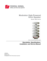
Figure 1-1. Model PA640.
The Federal Signal Model PA640 (figure 1-1) is a
precision built, efficient and economical full-featured
electronic siren and light control system. The siren
provides wail, yelp, and priority or high-low siren
tones as well as the horn ring transfer Tap II feature,
public address (PA), radio rebroadcast and an air
horn sound.
On-board relays in the unit allow centralized
control and wiring of primary, secondary, alley lights,
and auxiliary circuits with a lighted rubberized
membrane switch assembly. A convenient four-
position Mode slide switch allows simplified and
rapid selection of most common siren and lighting
functions and changes the horn ring function accord-
ingly to provide the Tap II feature.
The unit may be installed in negative ground
vehicles with 12-volt electrical systems. The siren
circuits are protected against failure by user-supplied
fuses. The audio power amplifier contains circuitry
that protects the output transistor stages against
speaker and wiring short circuits. The relay outputs
are protected against failure by user-supplied fuses.
No components protrude from the bottom of the siren
to interfere with mounting arrangements.
A noise-canceling microphone is provided. It
provides high quality voice reproduction without
feedback squeal. The microphone push-to-talk switch
overrides any siren sound for instant Public Address
use. PA volume is adjustable by means of a front
panel VOLUME control.
The PA640 is designed to drive one 11-ohm
impedance, high power (100W) speaker.
The horn ring transfer feature allows the driver
to change the siren sound from wail to yelp to prior-
ity/high-low to wail… via the vehicle’s horn ring. This
feature provides especially effective traffic clearing
capability. Each slide switch position can be individu-
ally programmed for siren dependency, transfer of the
horn ring, and selection of the no siren tone to be
either airhorn or peak and hold.
To reduce standby power consumption the power
output audio and pre-amplifiers are not powered
when not in use.
Other special features include:
• High degree of reliability is achieved
through the use of a crystal controlled
microprocessor, integrated circuits and
silicon output transistors.
• Programmable rubberized pushbuttons
with inserts. Each pushbutton can be
programmed to be either: inactive,
momentary, push on/push off, 8 second
timer, simultaneous, or alternate
flasher. The flash rate is selectable,
either 75 or 120 flashes per minute.
Relay pushbuttons can be attached to
slide switch positions 1, 2, or 3.
• The control panel is illuminated with
non-glare backlighting.
• Printed circuit boards using surface
mount technology provide improved
performance and durability under a
wide range of environmental conditions.
• Park-Siren Deactivator can deactivate
siren tones when the vehicle is shifted
into PARK.
• The wail and yelp siren tones comply
with SAE J1849 JUL2002 and CCR
Title 13 Class ‘A’ specifications.
• Siren tones can be programmed to be
dependent or independent of the slide
switch.
• An electronic beeper chirps upon
function selection. The beeper is dip
switch selectable to chirp every 10
seconds if a function is active.
• The siren tones can be selected by dip
switch to cut-out or coast down when
deactivated.
-1-

SECTION II
SPECIFICATIONS
Input Voltage .................................................................. 11 Vdc to 16 Vdc
Polarity ............................................................................ Negative ground electrical systems only
Standby Current ............................................................. 0mA (ignition off)
150mA (ignition on)
Operating Current .......................................................... 9.25A (at 13.6V with11-ohm load,
amplifier in wail, K1,2,3 energized)
Frequency Range ............................................................ 750 to 1500 Hz
Cycle Rate ....................................................................... Wail - 12.7 cycles/min. 4.7sec/cycle
Yelp - 165 cycles/min. 363mS/cycle
Voltage Output (approx.)................................................ 64V peak-to-peak
Audio Frequency Response ............................................ 330 to 3000Hz ±3dB
Harmonic Audio Distortion ............................................ 10% max. all power levels from 1/2 to
50 watts (330-3000Hz)
Operating Temperature Range ...................................... -30°C to +65°C
Dimensions (HWD) ......................................................... 2.75" x 6.63" x 8.00"
Net Weight ...................................................................... 4.4 lbs.
Shipping Weight (approx.) ............................................. 6.0 lbs.
Current Ratings for Relays
Total Output ................................................ 80A Combined Total all relays
Slide Switch Outputs
Mode 1........................................................ 30A
Mode 2........................................................ 30A
Mode 3........................................................ 30A per individual terminal
40A Combined Total for Mode 3
Pushbutton Switch Outputs
A-F.............................................................. 20A Each
-2-

SECTION III
PROGRAMMING
SAFETY MESSAGE TO OPERATORS OF FEDERAL SIGNAL ELECTRONIC SIRENS
AND LIGHT/SOUND SYSTEMS
WARNING
The lives of people depend on your safe
operation of Federal products. It is impor-
tant to read and follow all instructions
shipped with the products. In addition,
listed below are some other important
safety instructions and precautions you
should follow:
Qualifications
• To properly use an electronic siren and
speaker(s): you must have a good under-
standing of general vehicle operation, a high
proficiency in the use of safety warning
equipment, and thorough knowledge of state
and federal UNIFORM TRAFFIC CODES.
Sound Hazards
• Your hearing and the hearing of others, in or
close to your emergency vehicle, could be
damaged by loud sounds. This can occur
from short exposures to very loud sounds, or
from longer exposures to moderately loud
sounds. For hearing conservation guidance,
refer to federal, state, or local recommenda-
tions. OSHA Standard 1910.95 offers
guidance on “Permissible Noise Exposure.”
• All effective sirens and horns produce loud
sounds (120 dB) that may cause permanent
hearing loss. Always minimize your expo-
sure to siren sound, roll up your windows
and wear hearing protection. Do not sound
the siren indoors or in enclosed areas where
you and others will be exposed to the sound.
Only use the siren for emergency response
situations.
Sound Limitations
• Before using the vehicle, check to see if the
siren speakers are concealed from view. If
the siren speaker is not in clear view on the
front of the vehicle, use extra caution when
operating the vehicle. A concealed siren
speaker installation is less effective at
warning others.
• Maximum sound output will be severely
reduced if any objects are in front of the
speaker. If your installation has obstructions
in front of the speaker, drive even more
cautiously.
• Frequently inspect the speaker to ensure
that it is clear of any obstruction, such as
mud or snow, which will reduce maximum
sound output.
Signaling Limitations
• Be aware that the use of your visual and
audible signaling devices does not give you
the right to force your way through traffic.
Your emergency lights, siren, and actions
are REQUESTING the right-of-way.
• Although your warning system is operating
properly, it may not alert everyone. People
may not hear, see, or heed your warning
signal. You must recognize this fact and
continue driving cautiously.
• Situations may occur which obstruct your
warning signal when natural or man-made
objects are between your vehicle and others.
This can also occur when you raise your
hood or trunk lid. If these situations occur,
be especially careful.
• The LED indicators on the siren control
switches simulate the light pattern(s) being
executed by the warning system. The display
is intended ONLY as a guide and NOT as an
indication of proper warning system opera-
tion. Before using the warning system, its
operation should be observed from outside
the vehicle.
Driving Limitations
• At the start of your shift, you should ensure
that the light/sound system is securely
attached to the vehicle and operating
properly.
• If the unique combination of emergency
vehicle equipment installed in your vehicle
has resulted in the siren controls being
installed in a position that does not allow
you to operate them by touch only, OPER-
ATE CONTROLS ONLY WHILE YOUR
VEHICLE IS STOPPED.
• If driving conditions require your full
attention, you should avoid operating the
siren controls while the vehicle is in motion.
Continuing Education
• File these instructions in a safe place and
refer to them periodically. Give a copy of
these instructions to new recruits and
trainees.
Failure to follow these safety precautions may
result in property damage, serious injury, or death to
you, to passengers, or to others.
-3-

3-1. DEFAULT CONFIGURATION.
The PA640 siren is operational right out of the
box. It comes preconfigured according to the listing
that follows. All operation instructions on this page
are in reference to the default configuration.
Many of these functions, as well as some not
listed, can be changed to meet the user’s specific
needs. Make sure to take the time to read through
this manual to understand the full versatility of this
product. All warnings and cautions that appear in the
other sections of this manual also apply to informa-
tion given in this section. Make sure you are aware of
these warnings and cautions before you begin using
this section to reconfigure the PA640 siren.
DEFAULT CONFIGURATION LISTING:
Slide Switch Position OFF ……….Outputs 1, 2 &
3 are off.
Slide Switch Position 1 ……………Output 1 is
energized.
Slide Switch Position 2 ……………Output 1 & 2
are energized.
Slide Switch Position 3 ……………Output 1, 2 &
3 are energized.
Horn Ring Transferred, enabling TAPII function.
No Siren Tone is Peak and Hold.
Rotary Switch Position PRTY…… Enabled,
Priority tone selected
Pushbutton Switch A ………………Push On /
Push Off
Pushbutton Switch B ………………Push On /
Push Off
Pushbutton Switch C ………………Push On /
Push Off
Pushbutton Switch D ………………Push On /
Push Off
Pushbutton Switch E ………………Push On /
Push Off
Pushbutton Switch F ………………Push On /
Push Off
Audible Function Active Indicator… Chirp
disabled
Siren mode…………………………Standard, no
coast down.
Siren dependency…………………Siren depen-
dent on slide switch 3
Pushbutton dependency…………all pushbuttons
independent of slide switch positions.
-4-
3-2. PROGRAMMING.
Two factors control how the PA640 will operate,
DIP switch settings and EEPROM memory configu-
ration. Both can be accomplished in the field with
simple hand tools and the following instructions.
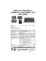
3-3. PREPARE UNIT FOR PROGRAMMING.
To change the operation of the PA640 proceed as
follows (see figure 3-1, 3-2 and 3-3):
A. Insure all power is turned off.
B. Place slide switch in the OFF position and
rotary switch in MANUAL.
C. Open unit by removing the four torx head
screws holding the cover to the chassis. With the
front of the siren facing you, place the relay board
(mounted in cover) to the right of the amplifier board.
Insure that the ribbon cable and ground cable are
connecting the two PCB assemblies. (See figure 3-1.)
3-4. DIP SWITCH PROGRAMMING.
The DIP switch SW3 on the amplifier PCB
assembly (see figure 3-2) is used to configure the
following siren functions:
A. Audible Function Active Indicator SW3-1
ON … A brief chirp will be heard every 10
seconds if any output function is active.
OFF … function is disabled.
B. Siren Mode SW3-2
ON … When turned off the siren will
continue its current cycle and coast down
before turning off.
OFF … Upon deactivation the siren will
shut off immediately.
C. Siren Dependency SW3-3
ON … Rotary switch siren functions
independent of slide switch programming.
OFF … Siren functions dependent on slide
switch programming.
D. EEPROM programming SW3-4
ON … Powering up the siren with SW3-4 in
the ON position will cause the siren to
enter EEPROM programming mode.
OFF … Turning SW3-4 OFF while powered
up will save the current EEPROM settings.
Powering up with SW3-4 OFF will begin
normal siren operation.
If programming is complete, continue to section
3-6 EXIT PROGRAMMING.

3-5. EEPROM PROGRAMMING.
EEPROM programming allows the operation of
the slide switch, rotary switch and pushbutton
switches to be changed to better fit the end users
requirements.
Open the siren as described in paragraph 3-3.
Prepare unit for programming. Place dip switch SW3-
4 in the ON position.
Turn on the power. Unit chirps. The siren is now
in programming mode.
A. Pushbutton Programming.
As supplied, the pushbutton switches
operate in a push-on/push-off mode. If desired, the
290A5190
GROUND CABLE
RIBBON CABLE
LED’s
Figure 3-1.
pushbutton switches can operate in an inactive mode,
momentary mode, timer mode, or simultaneous or
alternating flasher mode. To change pushbutton
switch operation proceed as follows (see figure 3-3):
1. If not already done, place the rotary
switch in the MANUAL position and the slide switch
in the OFF position.
2. Press and release the pushbutton
switch you wish to program. The unit chirps and the
pushbutton’s LED will illuminate signifying which
switch is being programmed. LED’s on the relay
board illuminate a code specifying how the switch is
currently operating.
3. Continue to depress and release the
pushbutton until the code matches the operation you
wish that switch to perform.
Function: Code:
CR1 CR3 CR2
Inactive OFF OFF OFF
Momentary ON OFF OFF
Push-On/Push-Off OFF OFF ON
Timer ON OFF ON
Flasher-A-Phase OFF ON OFF
Flasher-B-Phase ON ON OFF
4. Repeat steps B and C for the other
pushbuttons until all pushbuttons have been pro-
grammed.
If programming is complete, continue to
section 3-6 EXIT PROGRAMMING.
B. Slide Switch Off Programming.
As supplied, the slide switch OFF position
operates as follows:
• The horn ring is not transferred.
• The siren is disabled if dependent on slide
switch position.
• The no siren tone is Air Horn.
• Rotary switch position PRTY is enabled.
• The PRTY tone is Priority.
• Flasher set at 120 flashes per minute.
Pushbutton #7 (A/H) is used to change the
operation of 1, 2 & 3. Pushbutton #8 (MAN) is used
to change the operation of 4 & 5. To change slide
290A5191
GROUND CABLE
RIBBON CABLE
DIP SWITCHES
Figure 3-2. -5- Figure 3-3. Front View.
A/H
MAN
123
OFF
ABCDEF
VOLUME
MANUAL
RADIO PRTY
WAIL
YELP
290A5192

switch OFF position operation proceed as follows (see
figure 3-3):
1. If not already done, place the rotary
switch in the MANUAL position and the slide switch
in the OFF position.
2. Press and release pushbutton #7 (A/H)
switch. The unit chirps and the pushbutton’s LED
will illuminate signifying which functions are being
programmed. LED’s on the relay board illuminate a
code specifying how the switches functions are
currently operating.
3. Continue to depress and release the
pushbutton #7 until the code matches the operation
you wish that switch to perform.
Function: Code:
CR1 CR3 CR2
a. Horn Ring OFF xxx xxx
not transferred
a. Horn Ring ON xxx xxx
transferred
b. Siren disabled xxx xxx OFF
if dependent
b. Siren enabled xxx xxx ON
if dependent
c. No Siren Tone xxx OFF xxx
is Air Horn
c. No Siren Tone xxx ON xxx
is Peak and Hold
4. Press and release pushbutton #8
(MAN) switch. The unit chirps and the pushbutton’s
LED will illuminate signifying which functions are
being programmed. LED’s on the relay board illumi-
nate a code specifying how the switches functions are
currently operating.
5. Continue to depress and release
pushbutton #8 until the code matches the operation
you wish that switch to perform.
Function: Code:
CR1 CR3 CR2
a. Rotary Switch OFF xxx xxx
position PRTY
enabled
a. Rotary Switch ON xxx xxx
position PRTY
disabled
b. PRTY tone xxx xxx OFF
is priority
b. PRTY tone xxx xxx ON
is High Low
c. Flashers at xxx OFF xxx
120 Flashes per
minute
c. Flashers at xxx ON xxx
75 Flashes per
minute
If programming is complete, continue to
section 3-6 EXIT PROGRAMMING.
C. Slide Switch 1 Programming.
As supplied, the slide switch 1 position
operates as follows:
• The horn ring is not transferred.
• The siren is disabled if dependent on slide
switch position.
• The no siren tone is Air Horn.
• Relay Output #1 is active.
• No auxiliary relays are attached to slide
switch 1.
Pushbutton #7 (A/H) is used to change the
operation of 1, 2 & 3. Pushbutton #8 (MAN) is used
to change the operation of 4 & 5. To change slide
switch 1 position operation, proceed as follows (see
figure 3-3):
1. Place the rotary switch is in the
MANUAL position and the slide switch in the 1
position.
2. Press and release pushbutton #7 (A/H)
switch. The unit chirps and the pushbutton’s LED
will illuminate signifying which functions are being
programmed. LED’s on the relay board illuminate a
code specifying how the switch’s functions are cur-
rently operating.
3. Continue to depress and release the
pushbutton #7 until the code matches the operation
you wish that switch to perform.
Function: Code:
CR1 CR3 CR2
a. Horn Ring OFF xxx xxx
not transferred
a. Horn Ring ON xxx xxx
transferred
b. Siren disabled xxx xxx OFF
if dependent
b. Siren enabled xxx xxx ON
if dependent
c. No Siren Tone xxx OFF xxx
is Air Horn
c. No Siren Tone xxx ON xxx
is Peak and Hold
4. Press and release pushbutton #8
(MAN) switch. The unit chirps and the pushbutton’s
LED will illuminate signifying which functions are
being programmed. LED’s on the relay board illumi-
nate a code specifying how the switches functions are
currently operating.
-6-

5. Continue to depress and release
pushbutton #8 until the code matches the operation
you wish that switch to perform.
Function: Code:
CR1 CR3 CR2
a. Relay Output OFF xxx xxx
#1 is inactive.
a. Relay Output ON xxx xxx
#1 is active.
b. Relay Output xxx xxx OFF
#2 is inactive.
b. Relay Output xxx xxx ON
#2 is active.
c. Relay Output xxx OFF xxx
#3 is inactive.
c. Relay Output xxx ON xxx
#3 is active.
6. To attach an auxiliary relay to slide
switch 1, press the push button corresponding to the
relay you want to attach until the LED on relay
board illuminates. To release the relay, press until the
LED is off.
Function: Code:
Pushbutton: PB1 PB3 PB2 PB4 PB5 PB6
LED: CR1 CR3 CR2 CR4 CR5 CR6
Relay: K4 K6 K5 K7 K8 K9
Output: A C B D E F
Relay is OFF OFF OFF OFF OFF OFF
not attached.
Relay ON ON ON ON ON ON
is attached.
If programming is complete, continue to
section 3-6 EXIT PROGRAMMING.
D. Slide Switch 2 Programming.
As supplied, the slide switch 2 position
operates as follows:
• The horn ring is not transferred.
• The siren is disabled if dependent on slide
switch position.
• The no siren tone is Air Horn.
• Relay Output #1 and #2 are active.
• No auxiliary relays are attached to slide
switch 2.
Pushbutton #7 (A/H) is used to change the
operation of 1, 2 & 3. Pushbutton #8 (MAN) is used
to change the operation of 4 & 5. To change slide
switch 2 position operation, proceed as follows (see
figure 3-3):
1. Place the rotary switch in the
MANUAL position and slide switch in the 2 position.
2. Press and release pushbutton #7 (A/H)
switch. The unit chirps and the pushbutton’s LED
will illuminate signifying which functions are being
programmed. LED’s on the relay board illuminate a
code specifying how the switches functions are
currently operating.
3. Continue to depress and release the
pushbutton #7 until the code matches the operation
you wish that switch to perform.
Function: Code:
CR1 CR3 CR2
a. Horn Ring OFF xxx xxx
not transferred
a. Horn Ring ON xxx xxx
transferred
b. Siren disabled xxx xxx OFF
if dependent
b. Siren enabled xxx xxx ON
if dependent
c. No Siren Tone xxx OFF xxx
is Air Horn
c. No Siren Tone xxx ON xxx
is Peak and Hold
4. Press and release pushbutton #8
(MAN) switch. The unit chirps and the pushbutton’s
LED will illuminate signifying which functions are
being programmed. LED’s on the relay board illumi-
nate a code specifying how the switches functions are
currently operating.
5. Continue to depress and release
pushbutton #8 until the code matches the operation
you wish that switch to perform.
Function: Code:
CR1 CR3 CR2
a. Relay Output OFF xxx xxx
#1 is inactive.
a. Relay Output ON xxx xxx
#1 is active.
b. Relay Output xxx xxx OFF
#2 is inactive.
b. Relay Output xxx xxx ON
#2 is active.
c. Relay Output xxx OFF xxx
#3 is inactive.
c. Relay Output xxx ON xxx
#3 is active.
6. To attach an auxiliary relay to slide
switch 2, press push button corresponding to the
relay you want to attach until the LED on the relay
-7-

board illuminates. To release the relay press until the
LED is off.
Function: Code:
Pushbutton: PB1 PB3 PB2 PB4 PB5 PB6
LED: CR1 CR3 CR2 CR4 CR5 CR6
Relay: K4 K6 K5 K7 K8 K9
Output: A C B D E F
Relay is OFF OFF OFF OFF OFF OFF
not attached.
Relay ON ON ON ON ON ON
is attached.
If programming is complete, continue to
section 3-6 EXIT PROGRAMMING.
E. Slide Switch 3 Programming.
As supplied, the slide switch 3 position
operates as follows:
• The horn ring is transferred.
• The siren is enabled if dependent on slide
switch position.
• The no siren tone is Pear and Hold.
• Relay Output #1 #2 & #3 are active.
• No auxiliary relays are attached to slide
switch 3.
Pushbutton #7 (A/H) is used to change the
operation of 1, 2 & 3. Pushbutton #8 (MAN) is used
to change the operation of 4 & 5. To change slide
switch 3 position operation proceed as follows (see
figure 3-3):
1. Place the rotary switch in the
MANUAL position and the slide switch in the 3
position.
2. Press and release pushbutton #7 (A/H)
switch. The unit chirps and the pushbutton’s LED
will illuminate signifying which functions are being
programmed. LED’s on the relay board illuminate a
code specifying how the switches functions are
currently operating.
3. Continue to depress and release the
pushbutton #7 until the code matches the operation
you wish that switch to perform.
Function: Code:
CR1 CR3 CR2
a. Horn Ring OFF xxx xxx
not transferred
a. Horn Ring ON xxx xxx
transferred
b. Siren disabled xxx xxx OFF
if dependent
b. Siren enabled xxx xxx ON
if dependent
c. No Siren Tone xxx OFF xxx
is Air Horn
c. No Siren Tone xxx ON xxx
is Peak and Hold
4. Press and release pushbutton #8
(MAN) switch. The unit chirps and the pushbutton’s
LED will illuminate signifying which functions are
being programmed. LED’s on the relay board illumi-
nate a code specifying how the switch’s functions are
currently operating.
5. Continue to depress and release
pushbutton #8 until the code matches the operation
you wish that switch to perform.
Function: Code:
CR1 CR3 CR2
a. Relay Output OFF xxx xxx
#1 is inactive.
a. Relay Output ON xxx xxx
#1 is active.
b. Relay Output xxx xxx OFF
#2 is inactive.
b. Relay Output xxx xxx ON
#2 is active.
c. Relay Output xxx OFF xxx
#3 is inactive.
c. Relay Output xxx ON xxx
#3 is active.
-8-

6. To attach an auxiliary relay to slide
switch 3, press the pushbutton corresponding to relay
you want to attach until the LED on the relay board
illuminates. To release the relay, press until the LED
is off.
Function: Code:
Pushbutton: PB1 PB3 PB2 PB4 PB5 PB6
LED: CR1 CR3 CR2 CR4 CR5 CR6
Relay: K4 K6 K5 K7 K8 K9
Output: A C B D E F
Relay is OFF OFF OFF OFF OFF OFF
not attached.
Relay is ON ON ON ON ON ON
attached.
If programming is complete, continue to
section 3-6 EXIT PROGRAMMING.
3-6. EXIT PROGRAMMING.
After programming is completed, proceed as
follows:
-9-
If only DIP switch programming was performed,
insure SW3-4 is in the OFF position and proceed to
siren reassembly.
If EEPROM programming was performed:
A. Place dip switch 4 in the OFF position. Unit
chirps.
B. Cycle power off then on. This can be accom-
plished by removing and replacing jumper J6. Unit
chirps.
C. Test unit operation.
Test ALL operational modes of the siren to
insure that it is working properly.
D. Reassemble the siren.

SECTION IV
INSTALLATION
SAFETY MESSAGE TO INSTALLERS
OF
ELECTRONIC SIRENS
WARNING
The lives of people depend on your proper installation
and servicing of Federal products. It is important to
read and follow all instructions shipped with the
products. In addition, listed below are some other
important safety instructions and precautions you
should follow:
Before Installation
Qualifications
• To properly install an electronic siren: you must have a
good understanding of automotive electrical procedures
and systems, along with proficiency in the installation
and service of safety warning equipment. Always refer to
the vehicle’s service manuals when performing equip-
ment installations on a vehicle.
Sound Hazards
• Your hearing and the hearing of others, in or close to
your emergency vehicle, could be damaged by loud
sounds. This can occur from short exposures to very loud
sounds, or from longer exposures to moderately loud
sounds. For hearing conservation guidance, refer to
federal, state, or local recommendations. OSHA
Standard 1910.95 offers guidance on “Permissible Noise
Exposure.”
• All effective sirens and horns produce loud sounds (120
dB) that may cause permanent hearing loss. Always
minimize your exposure to siren sound and wear hearing
protection. Do not sound the siren indoors or in enclosed
areas where you and others will be exposed to the sound.
• Federal Signal siren amplifiers and speakers are
designed to work together as a system. Combining a
siren and speaker from different manufacturers may
reduce the warning effectiveness of the siren system and
may damage the components. You should verify or test
your combination to make sure the system works
together properly and meets federal, state and local
standards or guidelines.
During Installation
• DO NOT get metal shavings inside the product. Metal
shavings in the product can cause the system to fail. If
drilling must be done near the unit, place an ESD
approved cover over the unit to prevent metal shavings
from entering the unit. Inspect the unit after mounting
to be sure there are no shavings present in or near the
unit.
• DO NOT connect this system to the vehicle battery until
ALL other electrical connections are made, mounting of
all components is complete, and you have verified that
no shorts exist. If wiring is shorted to vehicle frame, high
current conductors can cause hazardous sparks resulting
in electrical fires or flying molten metal.
• Be sure the siren amplifier and speaker(s) in your
installation have compatible wattage ratings.
• In order for the electronic siren to function properly, the
ground connection must be made to the NEGATIVE
battery terminal.
• Sound output will be severely reduced if any objects are
in front of the speaker. If maximum sound output is
required for your application, you should ensure that the
front of the speaker is clear of any obstructions.
• Install the speaker(s) as far forward on the vehicle as
possible, in a location which provides maximum
signaling effectiveness and minimizes the sound
reaching the vehicle's occupants. Refer to the National
Institute of Justice guide 500-00 for further information.
• Mounting the speakers behind the grille will reduce the
sound output and warning effectiveness of the siren
system. Before mounting speakers behind the grille,
make sure the vehicle operators are trained and
understand that this type of installation is less effective
for warning others.
• Sound propagation and warning effectiveness will be
severely reduced if the speaker is not facing forward.
Carefully follow the installation instructions and always
install the speaker with the projector facing forward.
• DO NOT install the speaker(s ) or route the speaker
wires where they may interfere with the operation of air
bag sensors.
• Never attempt to install aftermarket equipment, which
connects to the vehicle wiring, without reviewing a
vehicle wiring diagram - available from the vehicle
manufacturer. Insure that your installation will not
affect vehicle operation and safety functions or circuits.
Always check vehicle for proper operation after
installation.
• DO NOT install equipment or route wiring or cord in the
deployment path of an air bag.
• Locate the siren controls so the vehicle, controls, and
microphone can be operated safely.
• When drilling into a vehicle structure, be sure that both
sides of the surface are clear of anything that could be
damaged.
After Installation
• After installation, test the siren system and light system
to ensure that it is operating properly.
• Test all vehicle functions, including horn operation,
vehicle safety functions and vehicle light systems, to
ensure proper operation. Ensure that installation has
not affected vehicle operation or changed any vehicle
safety function or circuit.
• After testing is complete, provide a copy of these
instructions to the instructional staff and all operating
personnel.
• File these instructions in a safe place and refer to them
when maintaining and/or reinstalling the product.
Failure to follow all safety precautions and instructions
may result in property damage, serious injury, or death to you
or others.
-10-

4-1. UNPACKING.
After unpacking the Model PA640, examine it for
damage that may have occurred in transit. If the
equipment has been damaged, file a claim immedi-
ately with the carrier stating the extent of damage.
Carefully check all envelopes shipping labels and
tags before removing or destroying them.
4-2. MOUNTING BRACKET.
WARNING
When installing equipment inside air
bag equipped vehicles, the installer
MUST ensure that the equipment is
installed ONLY in areas recommended
by the vehicle manufacturer.
Failure to observe this warning will
reduce the effectiveness of the air bag,
damage the air bag, or potentially
damage or dislodge the equipment,
causing serious injury or death to you
or others.
The unit comes equipped with a ‘U’ shaped
bracket that enables it to be mounted in a variety of
positions. Positioning the bracket above the unit
allows mounting to the underside of a surface.
Positioning the bracket below the unit will permit
mounting on any horizontal surface.
The unit should be mounted in a position that is
both comfortable and convenient to the operator. The
mounting position must allow the vehicle, controls,
and microphone to be operated safely at all times.
Keep visibility and accessibility of controls in mind.
To install the unit using the bracket, determine the
mounting location and proceed as follows (see figure
4-1).
CAUTION
The unit must be installed in an adequately
ventilated area. Never install near heater
ducts.
A. Use the mounting bracket as a template
and scribe two drill positioning marks at the selected
mounting location.
CAUTION
Before drilling holes in ANY part of a ve-
hicle, be sure that both sides of the mounting
surface are clear of parts that could be
damaged; such as brake lines, electrical
wiring or other vital parts.
B. Drill two, 1/4-inch diameter holes at the
position marks.
290A519
3
RADIO
REBROADCAST
VOLUME
ADJUST
Figure 4-1.
C. Secure the mounting bracket to the surface
with (2 each) 1/4-20 x 3/4 hex head screws, 1/4 split
lockwashers and 1/4-20 hex nuts as shown in figure
4-1. The unit will be secured to the mounting bracket
after wiring is completed.
4-3. ELECTRICAL INSTALLATION.
A. Siren Connections.
The unit is supplied with an eleven-position
connector to perform the electrical installation. User-
supplied 18-gauge red and black wires are required
for the ignition (+) and ground (-) connections. 18-
gauge wires are also required for the speaker (COM
& HI), horn ring and horn, radio, park (SOL & BCM),
and chassis ground connections.
To install a wire in the eleven-position
connector, strip 1/4" of insulation from the end of the
wire. Then insert the wire into the connector and
tighten the screw at the appropriate connector
position.
1. Speaker.
The unit is designed to operate with
one 11-ohm impedance speaker (100W). See figure 4-
2.
NOTE
If desired, the PA640 can be modified at the
factory to operate with 58W speakers.
Using 18 gauge wire, connect the speaker
leads to positions 10 and 11 of the eleven-position
connector as shown in figure 4-2.
-11-

+-
F
C
N.C.
N.O.
C
N.C.
N.O.
D
C
B
A
14 GA. WIRES
20 AMP
E
80 AMP
MAX
*
FUSIBLE
LINK
GROUND
12 GA. WIRE
*
11 PIN CONNECTOR
(1 SUPPLIED)
TYPICAL INSTALLATION
RADIO SPEAKER INPUT
VEHICLE HORN
HORN RELAY CONTACT
IGNITION
CUT
X
SPEAKER
SPEAKER COMMON
SPEAKER OUTPUT
CUT
X
STEERING LOCK SOLENOID
FOR CHEVY IMPALA
BODY
CONTROL
MODULE
– OR –
18 GA.
2 AMP
CASE GND.
1/4" INSULATED
FEMALE TERMINALS
WIRE
STRIPPING
TYPICAL
1/4"
18 GA.
(11)
*
CONNECTOR
STRIPPED WIRES
1/4"
#6 SPADE
TERMINAL
5/16"
MODE 3
MODE 3
40 AMP TOTAL
30 AMP MAX
PER TERMINAL
MODE 2
14 GA.
MODE 1
MODE 3
290A5194
Figure 4-2.
-12-

2. Radio.
See figure 4-2. To allow incoming radio
messages to be rebroadcast over the outside speakers,
connect user-supplied 18 gauge wires to positions 6
and 7 of the eleven-position connector. Connect the
other end of the 18 gauge wires across the two-way
radio’s speaker.
3. Horn Ring.
CAUTION
The horn ring transfer circuit of the siren is
capable of switching a maximum of 10-
amperes.
In order to utilize the horn ring trans-
fer features of the siren, the following procedure
must be performed.
a. Locate the wire that connects the
vehicle horn relay to the horn. Cut this wire.
b. See figure 4-2. Connect a user-
supplied 18 gauge wire to position 8 of the eleven-
position connector. Connect the other end of the wire
to the horn side of the cut wire. Insulate the connec-
tion.
c. See figure 4-2. Connect a user-
supplied 18 gauge wire to position 9 of the eleven-
position connector. Connect the other end of the wire
to the horn relay side of the cut wire. Insulate the
connection.
4. Park-Siren Deactivator.
IMPORTANT
It is the installer’s responsibility to deter-
mine an appropriate location in the vehicle
circuitry to connect this wire.
This feature automatically deactivates
siren tones when the vehicle is shifted into PARK.
See figure 4-2. Typical installations
connect a user-supplied 18 gauge wire to position 4
(BCM) of the eleven-position connector. Connect the
other end of the wire to a vehicle circuit that is
GROUNDED when the vehicle is shifted into PARK.
This is normally the transmission neutral safety
switch. Position 5 of the eleven-position connector is
not used.
WARNING
Test all vehicle functions, including
horn operation, vehicle safety functions
and vehicle light systems, to ensure
proper operation. Ensure that installa-
tion has not affected vehicle operation
or changed any vehicle safety function
or circuit.
For Chevy Impala installations locate
and cut the wire from the shift interlock solenoid to
the Body Control Module. Connect a user-supplied 18
gauge wire to position 4 (BCM) of the eleven-position
connector. Connect the other end of the wire to the
Body Control Module. Connect a user-supplied 18
gauge wire to position 5 (SOL) of the eleven-position
connector. Connect the other end of the wire to the
Shift Interlock Solenoid.
WARNING
Test all vehicle functions, including
horn operation, vehicle safety functions
and vehicle light systems, to ensure
proper operation. Ensure that installa-
tion has not affected vehicle operation
or changed any vehicle safety function
or circuit.
5. Power Source Connections.
The PA640 can operate from any 12-
volt negative ground vehicle electrical system. Power
for the unit can be obtained from the vehicle’s power
distribution center or directly from the vehicle
battery. If power is going to be obtained directly from
the vehicle battery, drill a hole in the vehicle firewall
for the power lead to enter the engine compartment.
Place a grommet or similar device in the hole to
protect the wire against damage from rough edges.
Using figure 4-2 as a guide, proceed as
follows:
CAUTION
Before drilling holes in ANY part of the
vehicle, ensure that both sides of the surface
are clear of parts that could be damaged;
such as brake lines, fuel lines, electrical
wiring or other vital parts.
-13-

a. Connect a user-supplied 18 gauge
green wire to position 1 (case ground) of the eleven-
position connector. Connect the other end of the wire
to the vehicle chassis as close as practical to the unit.
Scrape paint away from the selected bolt hole to
ensure a good electrical connection to the chassis.
b. Connect a user-supplied 18 gauge
black wire to position 2 of the eleven-position connec-
tor. Connect the other end of the wire to a common
ground, located near the vehicle battery, that is
connected directly to the negative battery terminal.
c. Connect a user-supplied 12 gauge
black wire to the GROUND terminal. Connect the
other end of the wire to a common ground, located
near the vehicle battery, that is connected directly to
the negative battery terminal.
CAUTION
Damage to unit will occur if not properly
fused. Ensure that an in-line fuse (20A) and
fuseholder are installed in the red wire
connected to the POWER terminal and that
an in-line fuse (2A) and fuseholder are
installed in the red wire connected to posi-
tion 3 of the eleven-position connector.
d. Connect a user-supplied 18 gauge
red wire to position 3 of the eleven-position connector.
Route the wire toward the power source. To protect
the wire, use an in-line fuseholder and 2-ampere fuse
(not supplied). The fuseholder should be installed as
close as practical to the power source. Do not connect
to the power source at this time.
e. Connect a user-supplied 12 gauge
red wire to the POWER terminal. Route the wire
toward the power source. To protect the wire, use an
in-line fuseholder and 20-ampere fuse (not supplied).
The fuseholder should be installed as close as practi-
cal to the power source. Do not connect to the power
source at this time.
B. Light Bar and Auxiliary Light Connections
(see figure 4-2).
IMPORTANT
The total combined current maximum for all
outputs, 1 through 3 and A through D, must
not exceed 80-amperes. Also, individual
maximum current for 1 through 3 must not
exceed 30-amperes per terminal, 40-amperes
maximum combined in mode 3 and, indi-
vidual maximum currents for A through F
must not exceed 20-amperes.
The PA640 provides connections for control
of light bars, auxiliary lights and accessories. A total
of nine relay-controlled outputs are available.
Each output switches a nominal +12-volts
to the controlled device. DO NOT use the PA640
ground circuit to ground the switched device(s).
Ground each switched device SEPARATELY.
Refer to the installation instructions
provided with the light bar or auxiliary light for
additional precautions and details.
When connecting light bar and auxiliary
light wires to the PA640, each wire must be termi-
nated with an appropriate 1/4" female, insulated,
quick-connect terminal or #6 spade or ring terminal.
Complete the wiring to the light bar or accessories as
follows:
1. Using a user-supplied butt connector,
connect an 8 gauge red wire to the 8 gauge red wire
that exits the unit. Since this wire provides the power
source for all switched lighting functions, good
mechanical and electrical connections are important.
2. Route the 8 gauge red wire to the
power source. DO NOT make any connections to the
power source until all wiring is complete.
3. To protect the 8 gauge red wire, install
a user-supplied system appropriate circuit breaker of
sufficient amperage (80 ampere maximum) as close
as practical to the positive (+) power source terminal.
4. Connect wires from the light bar or
accessories to terminals 1 through 3. Refer to the
instructions supplied with the light bar or accessory
for current requirement, proper wire gauge, and any
additional instructions. Remember, each output can
supply 30 amperes and the total combined current
available is 80-amperes. Install appropriate user-
supplied in-line fuses in each wire as close to the
PA640 as possible.
NOTE
Output E and F are isolated from the +12-
volt battery supply for switching other
POSITIVE or NEGATIVE voltages. See
figure 4-3.
WARNING
DO NOT connect any relay to brake
light circuit of ANY vehicle.
DO NOT connect any relay to the head-
light circuit of any vehicle.
-14-

5. Connect wires from the accessories to
terminals A through F. Refer to the instructions
supplied with the accessories for current require-
ment, proper wire gauge, and any additional instruc-
tions. Remember, each output can supply 20-amperes
and the total combined current available is 80-
amperes including outputs 1 through 3. Install
appropriate user-supplied in-line fuses in each wire
as close to the PA640 as possible.
4-4. PUSHBUTTON SWITCH OPTION.
As supplied, the pushbutton switches operate in
a push-on/push-off mode. If desired, the pushbutton
switches can operate in an inactive mode, momentary
mode, timer mode, or simultaneous or alternating
flasher mode. To change a pushbuttons operation, see
Section III PROGRAMMING of this manual.
4-5. FUNCTION LABEL INSTALLATION.
See figure 4-4. Replaceable function labels
identify the auxiliary switches. A sheet of applicable
function legends is supplied.
To install the function legends, proceed as
follows:
Select the appropriate labels from the supplied
sheet of function legends. Peel the labels from the
sheet and apply to the area provided in the rubber-
ized switches.
4-6. SIREN FUNCTION SELECT.
As received from the factory, the unit produces
wail, yelp, or priority tones ONLY if the slide switch
is set to position 3. The siren tone/activation is
dependent on the slide switch position.
If desired, the siren tones can sound immedi-
ately when the desired tone is selected with the
selector switch. The siren tones can be independent of
the slide switch position.
To change the siren tones to independent opera-
tion refer to Section III PROGRAMMING in this
manual.
ABCD
K3 K2 K1 K4 K5 K6 K7 K8 K9
NO NC CNO NC C
12
3EF
290A5195
Figure 4-3.
NOTE
Inform the operator whether the siren
operates dependently or independently of
the slide switch.
4-7. RADIO REBROADCAST VOLUME
ADJUSTMENT.
After the unit is completely installed in the
vehicle, set the siren function selector switch to
RADIO. First, adjust the radio receiver volume for a
comfortable listening level inside the vehicle. Next,
stand outside of the vehicle and note the radio
rebroadcast loudness. If the sound volume is too loud
or too soft, adjust the radio rebroadcast level control
through the hole on the side of the siren (see figure 4-
1) to the desired sound level.
4-8. INSPECTION AND FINAL INSTALLATION.
A. Plug the eleven-position connector into the
mating connector on the unit, and apply pressure
until it locks into place.
CAUTION
To avoid damage to the unit, the BLACK 1/4-
20 x 7/16 hex head cap screws and the 1/4
split lockwashers MUST be used as shown in
figure 4-1.
B. Secure the unit to the mounting bracket
with the black 1/4-20 x 7/16 hex head screws and 1/4
split lockwashers.
C. Tilt the unit to the desired position. Tighten
the 1/4-20 x 7/16 hex head screws.
D. Before connection to the power source,
perform a visual check of all connections and wiring.
E. Ensure that there are no loose wire strands
or other bare wire which may cause a short circuit.
LOW
POWER
DOOR
AREA
P
AUX 1
WAIL WAIL
DOM
AUX 2
A / H
AU
FAST
290A5196
LEGEND INSERT
(REMOVED
FROM SHEET)
LEGEND SHEET
BLANK
KEYPAD
KEYBOARD
T
Figure 4-4.
-15-

-16-
Also, all wires must be protected from any sharp
edges which could eventually cut through the insula-
tion.
F. Use an ohmmeter to verify that a short
circuit does NOT exist between the positive (+) leads
and the vehicle chassis.
WARNING
If wires are shorted to the vehicle frame
or each other, high current conductors
can cause hazardous sparks resulting in
electrical fires and molten metal.
Verify that no short circuits exist before
connecting to the Positive (+) battery
terminal.
DO NOT connect this system to the
vehicle battery until ALL other electri-
cal connections are made and mounting
of all components is complete.
Failure to observe this WARNING will
result in fire, burns and blindness.
G. Connect all red (+) wires to the positive (+)
terminal of the power source. Secure mechanical and
electrical connections are required.
4-9. WIRE MANAGEMENT.
The hardware kit for the PA640 includes cable
ties and cable tie holders. These parts enable the
installer to quickly and easily manage the wires that
make the connections to the PA640. After installa-
tion, these components help secure the connections,
greatly reducing the chance of accidental disconnec-
tion. Additionally, wires may be disconnected by
simply cutting the cable tie and then rebundling with
standard cable ties. To install, proceed as follows:
A. See figure 4-5. Insert the cable tie holder
into one of the two .250" diameter holes provided in
the back of the unit.
B. Feed a cable tie through the opening in the
cable tie holder.
C. When all connections are made, route wires
in a manner that allows convenient bundling with
the cable tie.
D. Tighten the cable tie and trim the excess tie
material.
4-10. TESTING AFTER INSTALLATION.
WARNING
All effective sirens and horns produce
loud sounds (120 dB) that may cause
permanent hearing loss. Always mini-
mize your exposure to siren sound and
wear hearing protection. Do not sound
the siren indoors or in enclosed areas
where you and others will be exposed to
the sound.
After installation; test the electronic siren,
including horn operation, to ensure that it is operat-
ing properly.
After testing is complete, provide a copy of this
manual to all operating personnel.
Figure 4-5.
CABLE TIE
CABLE TIE HOLDER
290A5228

SECTION V
OPERATION
SAFETY MESSAGE TO OPERATORS OF
FEDERAL SIGNAL ELECTRONIC SIRENS
AND LIGHT/SOUND SYSTEMS
WARNING
The lives of people depend on your safe
operation of Federal products. It is impor-
tant to read and follow all instructions
shipped with the products. In addition,
listed below are some other important
safety instructions and precautions you
should follow:
Qualifications
• To properly use an electronic siren and
speaker(s): you must have a good under-
standing of general vehicle operation, a high
proficiency in the use of safety warning
equipment, and thorough knowledge of state
and federal UNIFORM TRAFFIC CODES.
Sound Hazards
• Your hearing and the hearing of others, in or
close to your emergency vehicle, could be
damaged by loud sounds. This can occur
from short exposures to very loud sounds, or
from longer exposures to moderately loud
sounds. For hearing conservation guidance,
refer to federal, state, or local recommenda-
tions. OSHA Standard 1910.95 offers
guidance on “Permissible Noise Exposure.”
• All effective sirens and horns produce loud
sounds (120 dB) that may cause permanent
hearing loss. Always minimize your expo-
sure to siren sound, roll up your windows
and wear hearing protection. Do not sound
the siren indoors or in enclosed areas where
you and others will be exposed to the sound.
Only use the siren for emergency response
situations.
Sound Limitations
• Before using the vehicle, check to see if the
siren speakers are concealed from view. If
the siren speaker is not in clear view on the
front of the vehicle, use extra caution when
operating the vehicle. A concealed siren
speaker installation is less effective at
warning others.
• Maximum sound output will be severely
reduced if any objects are in front of the
speaker. If your installation has obstructions
in front of the speaker, drive even more
cautiously.
• Frequently inspect the speaker to ensure
that it is clear of any obstruction, such as
mud or snow, which will reduce maximum
sound output.
Signaling Limitations
• Be aware that the use of your visual and
audible signaling devices does not give you
the right to force your way through traffic.
Your emergency lights, siren, and actions
are REQUESTING the right-of-way.
• Although your warning system is operating
properly, it may not alert everyone. People
may not hear, see, or heed your warning
signal. You must recognize this fact and
continue driving cautiously.
• Situations may occur which obstruct your
warning signal when natural or man-made
objects are between your vehicle and others.
This can also occur when you raise your
hood or trunk lid. If these situations occur,
be especially careful.
Driving Limitations
• At the start of your shift, you should ensure
that the light/sound system is securely
attached to the vehicle and operating
properly.
• If the unique combination of emergency
vehicle equipment installed in your vehicle
has resulted in the siren controls being
installed in a position that does not allow
you to operate them by touch only, OPER-
ATE CONTROLS ONLY WHILE YOUR
VEHICLE IS STOPPED.
• If driving conditions require your full
attention, you should avoid operating the
siren controls while the vehicle is in motion.
Continuing Education
• File these instructions in a safe place and
refer to them periodically. Give a copy of
these instructions to new recruits and
trainees.
Failure to follow these safety precautions may
result in property damage, serious injury, or death to
you, to passengers, or to others.
-17-

5-1. GENERAL.
All controls utilized during operation of the
Model PA640 are located on the front panel of the
unit (see figure 5-1). They comprise:
1. A five-position rotary type siren function
Selector switch.
2. A four-position mode selector slide switch.
3. Six lighted (A, B, C, D, E, F) push-on/push-off
pushbuttons.
4. A public address volume control.
5. A momentary AIR HORN pushbutton switch.
6. A momentary MANUAL pushbutton switch.
The five-position rotary siren Function selector
switch determines what siren sound is generated
when the siren is enabled in mode 3.
NOTE
As received from the factory, the siren tones
are dependent on the slide switch position.
If desired, the siren tones can sound immedi-
ately when the desired tone is selected with
the selector switch. The siren tones can be
independent of the slide switch position.
To change the siren tones to independent
operation, see Section III PROGRAMMING
in this manual.
The four-position Mode selector switch controls
the operation of the warning lights and enables the
siren in Mode 3. In modes OFF, 1, and 2; only the
MANUAL and AIR HORN pushbutton siren sounds
are available.
5-2. SIREN FUNCTION SELECTOR SWITCH.
See figure 5-1. This five-position rotary switch
determines what siren function / sound is generated
when the siren is enabled. This switch does not effect
any light operation. The five switch positions are
described below:
A. RADIO.
In this position, incoming radio messages
are amplified by the siren and rebroadcast over the
outside speaker.
B. MAN.
In this position, it is possible to operate the
siren by activating the AIR HORN or MANUAL
pushbutton switches. The siren can also be activated
by means of the vehicle horn ring if the horn ring
transfer relay is enabled.
A/H
MAN
123
OFF
ABCDEF
VOLUME
MANUAL
RADIO PRTY
WAIL
YELP
290A5197
Figure 5-1.
C. WAIL.
In this position, the siren produces a
continuous “wailing” sound, up and down in fre-
quency.
D. YELP.
In this position, a continuous rapid
“warbled” tone is generated.
E. PRIORITY.
In this position, a continuous extremely
rapid “warbled” tone is generated.
NOTE
Pressing the microphone push-to-talk switch
will override any siren sound and provide
instant public address operation.
5-3. VEHICLE HORN RING SWITCH.
The horn ring transfer relay determines the
function of the vehicle horn ring switch. With the
siren powered off, the horn ring will operate the
vehicle horn. In slide switch position OFF, 1, and 2
the horn ring is not transferred and, the horn ring
will operate the vehicle horn. In slide switch position
3 the horn ring transfer relay is energized and the
siren activates the Tap II function and changes the
audible siren sound if the siren is active. If the siren
selector switch is in the MANUAL position the peak-
and-hold siren will sound.
The horn ring transfer relay operation can be
programmed based on slide switch position. See slide
switch programming in Section III PROGRAMMING
in this manual.
5-4. AIR HORN / MANUAL SIREN PUSHBUTTON
SWITCHES.
The AIR HORN pushbutton switch activates the
air horn sound in any selected position. Only public
address mode, the microphone’s Press To Talk switch
overrides the air horn.
The MANUAL pushbutton switch activates the
peak-and-hold sound in any selected position. Only
-18-
/