Page is loading ...

INSTALLATION AND PROGRAMMING GUIDE
734N Series Access
Control Modules


About the 734N Series .............................. 1
Power Supply ................................................................... 1
Zone Terminals ................................................................. 1
Annunciators..................................................................... 1
Indicator LEDs .................................................................. 1
Form C Relay ................................................................... 2
Programming Connection .......................................... 2
Wiegand and OSDP Reader Support ..................... 2
Local Event Storage ...................................................... 2
PCB Features ...............................................3
Install the 734N Series Module.................4
Mount the 734N .............................................................. 4
Wire the Access Control Lock .................................. 5
Isolation Relay (optional) ............................................ 8
Install the 333Suppressor .......................................... 9
Wire the Zone Terminals ............................................10
Connect a Wiegand Card Reader ...........................12
Connect an OSDP Card Reader ..............................15
Network Connection ....................................................19
Set the 734N Address ................................................20
Connect the Power Supply ......................................22
TABLE OF CONTENTS
Program the Panel ....................................23
Device Setup ..................................................................23
Device Number .................................................................23
Device Name ...................................................................... 23
Device Type ........................................................................24
Communication Type ......................................................24
Program the 734N Series Module ..........25
734N Menu ...................................................26
Programmer Menu ....................................................... 26
Initialization Options ...................................................27
Initialize Communication .............................................27
Initialize Access ...............................................................27
Communication Menu ................................................28
734N Device Number .....................................................28
734N DHCP ........................................................................28
734N IP Address ............................................................... 28
Subnet Mask.......................................................................28
Gateway Address .............................................................29
Panel IP Address...............................................................29
Panel IP Port ......................................................................29
734N Passphrase .............................................................. 29

Access Options ............................................................ 30
Reader Protocol Type .................................................... 30
Activate Zone 2Bypass .................................................32
Activate Zone 3 Request to Exit .................................34
Activate Onboard Speaker ...........................................35
Card Formats ..................................................................... 35
Require Site Code ............................................................38
Number of User Code Digits .......................................39
Card Format Added/Changed (Custom Format) 40
No Communication with Panel .................................. 40
Stop ...................................................................................41
Test the 734N Series Module ................. 42
734N Menu ...................................................42
Diagnostics Menu ............................................................42
Zone Status Display ........................................................43
Public Card Formats ............................... 44
734N Series Network Specifications .... 45
Compliance Listing Specifications ........47
UL Access Control .......................................................47
ULC Commercial Burglary (XR150/XR550Series
Panels) ..............................................................................49
Certifications ............................................ 50
Underwriters Laboratory (UL Listed) ................. 50
Product Specifications ............................ 51
Readers and Credentials .........................53

Digital Monitoring Products, Inc. | 734N Series Installation and Programming Guide 1
Annunciators
An onboard programmable piezo provides
local annunciation at the module. You can
also connect a variety of switched ground
annunciators to the module for remote
annunciation.
Indicator LEDs
734N Series modules provide three
indicator LEDs:
• RELAY (red) turns on for the same
duration as the door strike relay.
• WIEGAND (yellow) turns on for one
second to indicate receipt of valid input.
• DATA (green) indicates that the module
is communicating with the panel.
The 734N and 734N‑POE Access Control Modules allow you to add IP network access
control capability to XR150/XR550Series panels using proximity, credential, or
mag‑stripe card readers. The modules also allow you to use the powerful built‑in access
control capability of DMP Panels.
Power Supply
734N Series modules operate at
12/24VDC from the power supply
supporting a door’s magnetic lock or
door‑strike. The 734N‑POE can also be
powered from POE.
Warning: To avoid the risk of
equipment damage, do not exceed
750mA total output current for
zones connected to the module.
Zone Terminals
Four input zones are provided to allow
connection of nearby burglary devices.
ABOUT THE 734N SERIES

2 734N Series Installation and Programming Guide | Digital Monitoring Products, Inc.
Form C Relay
The 10Amp Form C relay draws up to
35mA of current. Refer to “Wire the
Access Control Lock” and “Isolation Relay
(optional)” in this document for more
information.
Programming Connection
The modules also provide a keypad
programming connection that allows
you to use a standard DMP LCD keypad
for initial setup. Programming can be
completed using a keypad connected to
the module or from XR150/XR550panels.
Wiegand and OSDP Reader
Support
The 734N Series supports both Wiegand
and OSDP card readers. For information
on compatible readers, refer to “Readers
and Credentials”. OSDP support requires
734N/734N‑POE modules with PCB Rev 9
and higher.
Local Event Storage
When communication is lost with the
panel, 734N and 734N‑POE Access
Control Modules store access granted
events locally in module memory. When
communication is reestablished, stored
events are sent and synced with panel
events, then inserted into the event buer
according to the actual time when they
occurred. To enable local event storage,
CARD FORMAT must be set to DMP or
CUSTOM and NO COMM WITH PNL must
be set to SITE or ANY.
Local Event Storage requires 734N/734N‑
POE modules with firmware Version 105
or higher, along with XR Series firmware
Version 202 or higher.

Digital Monitoring Products, Inc. | 734N Series Installation and Programming Guide 3
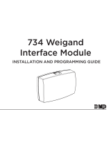
PCB FEATURES
DC
Input
Reader
Inputs
Zones
Piezo
Indicator
LEDs
Door Relay
Network
Connection
Figure 1: PCB Features
Keypad
Programming
Header
Status
Indicator
Outputs
Output 1
Reset Header
Output 2

4 734N Series Installation and Programming Guide | Digital Monitoring Products, Inc.
INSTALL THE 734N SERIES MODULE
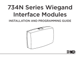
Mount the 734N
The module comes in a high‑impact plastic housing that you can mount directly to a
wall, backboard, or other flat surface.
For easy installation, the back and ends of the 734N housing have wire entrances. The
back also contains multiple mounting holes that allow you to mount the module on
a single‑gang switch box. DMP recommends mounting the 734N near the protected
door. Refer to Figure 2for mounting hole locations on the housing base.
1
1. Remove the PCB from the
plastic housing by loosening
the clips on one side and gently
lifting it out of the housing base.
2. Insert the included screws in the
desired mounting hole locations
and tighten them to secure the
housing to the surface.
3. Reinstall the PCB in the housing
base.
Mounting Holes
Figure 2: Mounting Hole Locations

Digital Monitoring Products, Inc. | 734N Series Installation and Programming Guide 5
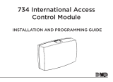
Wire the Access Control Lock
The module provides a Form C (SPDT) relay for controlling locks and other
electronically‑controlled barriers. The three relay terminals marked NO C NC allow
you to connect the device wiring to the relay for module control.
When the 734N Series module is powered with a 12/24V power supply, the device
can power an electric strike, up to 750mA. See Figure 3 and Figure 4 for typical
magnetic lock and door strike wiring. The 734N‑POE can also be powered with POE.
See Figure 5for POE door strike wiring.
The Form C relay draws up to 35mA of current and contacts are rated for 10Amps
(resistive) at 12/24VDC. When connecting multiple locks to the Form C relay, the
total current for all locks cannot exceed 10Amps. If the total current for all locks
exceeds 10Amps, problems may arise and an isolation relay may be needed. See
“Isolation Relay (optional)” for more information.
2

6 734N Series Installation and Programming Guide | Digital Monitoring Products, Inc.
Model 333
Suppressor
–+
12/24 VDC
Power Supply
734N
Normally Closed
Magnetic Door
Lock
Mag lock positive
to 734N terminal NC
Power supply positive
to 734N terminal C
Mag lock negative to
power supply negative
Figure 3: Typical Magnetic Lock Wiring
Model 333
Suppressor
–+
12/24 VDC
Power Supply
734N
Normally Open
Door strike positive
to 734N terminal NO
Power supply positive
to 734N terminal C
Door strike negative to
power supply negative
DC Door Strike
Figure 4: Typical Door Strike Wiring

Digital Monitoring Products, Inc. | 734N Series Installation and Programming Guide 7
RED WHT GRN BLK Z1 Z2 Z3 Z4+ Z4–GND GND
Door Strike
Card Reader
POE Switch or Injector
Red
Red
White
Green
Black
Black
Figure 5: Typical Door Strike Wiring with POE (734N‑POE only)

8 734N Series Installation and Programming Guide | Digital Monitoring Products, Inc.
Isolation Relay (optional)
The Form C relay can control a device that draws less than 10Amps of current. If a
device draws more than 10Amps of current, or the sum of all devices controlled by
the Form C relay exceeds 10Amps, an isolation relay must be used. Refer to Figure 6
and Figure 7 for isolation relay wiring.
3
Figure 6: Magnetic Lock with an
Isolation Relay
Figure 7: Door Strike with an
Isolation Relay
Normally
Closed
Common
Magnetic Lock
–+
12/24VDC
Power
Supply
734N
Series
Module
DC Input
Model 333
Suppressor
+
+
+
+
–
–
–
Mag Lock
Normally
Open
–+
DC Door Strike
12/24VDC
Power
Supply
734N
Series
Module
DC Input
+
+
+
+
–
–
–
Common
Model 333
Suppressor

Digital Monitoring Products, Inc. | 734N Series Installation and Programming Guide 9
734N
Interface
Module
Model 333
Suppressor
Install the 333Suppressor
Use the included 333suppressor with the 734N Series module to suppress any
surges caused by energizing a magnetic lock or door strike.
Install the 333across the module’s C (common) and NO (normally open) or NC
(normally closed) terminals.
If the device being controlled by the relay is connected to the NO and C terminals,
install the suppressor on the NO and C terminals.
Conversely, if the device is connected to the NC and C terminals, install the
333Suppressor on NC and C terminals.
The suppressor wire is non‑polarized. Install the suppressor as shown in Figure 8.
4
Figure 8: 333Suppressor Installation

10 734N Series Installation and Programming Guide | Digital Monitoring Products, Inc.
Wire the Zone Terminals
Terminals 5 through 9 connect grounded zones 1 through 3. These zones have a
grounded side and cannot be used for fire‑initiating devices. Zones 2 and 3 can
also be used for access control with Zone 2 providing a bypass option and Zone 3
providing Request to Exit functionality. Zone 4 terminals provide a non‑powered
Class B, Style A zone.
Use the supplied DMP Model 311 1k Ohm End‑of‑Line resistors on each zone. Refer to
the panel programming guide for programming instructions. See Figure 9for more
information on wiring the zone terminals.
Auxiliary Outputs1 & 2
The module controls Auxiliary Outputs1and 2when the Activate Zone 2Bypass
programming option is enabled and the Zone 2Bypass Time is set. When the door
contact (zone2) is opened while the door strike is activated, the Zone 2Bypass
Time starts. If the door has not closed at the end of the timer, AuxOutput1is turned
on and the timer starts again. If the door is still open at the end of the second timer,
AuxOutput2is turned on. AuxOutputs1and 2turn o when the door contact is
closed. Use the Model 431Relay Harness for connection of Output1and Output2.
5

Digital Monitoring Products, Inc. | 734N Series Installation and Programming Guide 11
Figure 9: Zone Terminal Wiring
Zone 1
Zone 2
Zone 3
Zone 4
1k Ω EOL
1k Ω EOL
1k Ω EOL
1k Ω EOL
1
2
3
4 5 6 7
8
10
11
9
Zone 3 can also
be wired normally
closed with an
in-line 1k Ohm
resistor
Table 1: 734N Zone Uses
Zone # Recommended Device Residential Fire Device?
1 Any burglary device No
2 Door contact No
3 REX (PIR or Button) No
4 Any Device No

12 734N Series Installation and Programming Guide | Digital Monitoring Products, Inc.
Connect a Wiegand Card Reader
The 734N Series module provides direct 12/24VDC, 200mA output to the
reader on the Red terminal connection. Figure 10 shows a reader with wire
colors RED, WHT, GRN, and BLK connecting to Terminals 1, 2, 3, and 4.
The green wire carries Data Zero (D0), and the white wire carries Data One (D1).
The red wire connects 12/24VDC, 200mA maximum power and the black wire
is ground.
The wire colors may be dierent depending on the reader being installed. Refer
to the literature provided with the reader for wire coding, wire distance, cable
type (such as shielded), and other specifications.
Wiegand Status Indicator Outputs
Terminals 5, 6, and 7 provide connections for Remote LED Control, Remote
Annunciation, and Armed Status indicators.
6a

Digital Monitoring Products, Inc. | 734N Series Installation and Programming Guide 13
LC (Remote LED Control)
Remote LED Control provides an unsupervised switched ground for a visual indicator
that turns on when the relay activates. Connect the wire from the LC Terminal to an
LED. The LED turns on for the duration the door strike relay is on. HID readers optionally
provide a connection for LED reader control.
LC Wire Color LED Color
Orange Green
Brown Red
RA (Remote Annunciation)
Remote Annunciation provides an unsupervised switched ground for a remote
annunciator that turns on when the Zone 2Bypass timer expires. Connect the wire from
the RA Terminal to a remote annunciator. The remote annunciator silences when the RA
restores. The remote annunciator (RA) switched ground operates even if the speaker is
programmed not to operate.
AS (Armed Status)
Armed Status provides an unsupervised switched ground for a visual or audible armed
status indicator that turns on when the burglary areas are armed, such as SYSTEM ON or
ALL SYSTEM ON. Connect a wire from the AS Terminal to an armed status indicator.
Caution: Status indicator outputs support a maximum of 100mA per terminal.
Exceeding the maximum rating on LC, RA, or AS terminals can damage equipment.

14 734N Series Installation and Programming Guide | Digital Monitoring Products, Inc.
Figure 10: Wiegand Card Reader Wiring
Red (12/24VDC)
Black (GND)
Green (Data 0)
White (Data 1)
Wiegand
Card Reader
Orange or Brown
Yellow
RED WHT GRN BLK Z1 Z2 Z3 Z4+ Z4–GND GND
AS
RA
LC
Yellow to RA
Orange or Brown to LC

Digital Monitoring Products, Inc. | 734N Series Installation and Programming Guide 15
Connect an OSDP Card Reader
The 734N Series provides 12/24VDC, 200mA power to the reader on the RED
terminal connection and two‑way data transmission on the GRN and WHT
connection. Only one OSDP reader can be connected to a module.
Use 24 AWG or larger two conductor RS‑485cable to connect a reader to
module terminals. For data transmission, connect the A (485 –) wire to the GRN
terminal and the B (485 +) wire to the WHT terminal. For reader power, connect
the red (DC +) wire to the RED terminal and the black (DC –) wire to the BLK
terminal. Refer to Figure 11.
Wire colors may be dierent depending on the reader. Refer to literature
provided with the reader for wire coding, distance, and other specifications.
Note: OSDP card readers require 734N Series Access Control modules with
PCB Rev 9 and higher.
6b

16 734N Series Installation and Programming Guide | Digital Monitoring Products, Inc.
OSDP Reader LED Operation
OSDP readers connected to 734N Series modules provide visual indication of relay
condition, connection type, and encryption status with a red and green LED. Enable
reader LED operation in LED CONTROL.
If enabled, the reader LED is turned on and operates the same as a Wiegand reader LED,
lighting green when the module relay activates. Visual indication for connection and
encryption status functions as follows:
• Fast blink (50 ms interval)—Connection secure, encrypted with 128‑bitAES and
your custom secure key.
• Slow blink (100 ms interval)—Connection encrypted with the default SIA secure
key.
• None—Connected, but not secure or encrypted.
If disabled, the reader LED is turned o and does not operate in any condition.
OSDP Reader Annunciation
OSDP readers connected to 734N Series modules provide audible indication of card
reads. Enable reader annunciation in BUZZER CONTROL.
If enabled, the reader’s internal annunciator follows normal RA terminal operation.
If disabled, the reader’s internal annunciator will beep once when a credential is
presented.
/